|

|
Forum Index : Electronics : Various aspects of home brew inverters
| Author | Message | ||||
renewableMark Guru Joined: 09/12/2017 Location: AustraliaPosts: 1678 |
Anyone building one would have plenty of 4008's on hand, why not just use them? Cheers Caveman Mark Off grid eastern Melb |
||||
| poida Guru Joined: 02/02/2017 Location: AustraliaPosts: 1418 |
noneyabussiness: Hip4082? I am not so sure. If I read the datasheet correctly, you will need a NOT gate as well as a HIP4082. Two ICs anyway. The IR21844 can drive 4 or 5 MOSFETs directly. I intend to drive my home inverter board directly using this design. Cost savings are small compared to the cost of everything else in my view. Mouser shows $5 each. so you save maybe $7. wronger than a phone book full of wrong phone numbers |
||||
| poida Guru Joined: 02/02/2017 Location: AustraliaPosts: 1418 |
Or pretty much any TO-220 basic N type such as IRFZ44 or similar logic level device. I've pulled plenty of suitable MOSFETs out of junk electronics. So maybe allocate a TO-220 footprint for both fan drives? wronger than a phone book full of wrong phone numbers |
||||
| tinyt Guru Joined: 12/11/2017 Location: United StatesPosts: 438 |
OK, I just named it generic N-CH/TO-220. Builders can use whatever they think will work. I also changed the relay driver to this generic mosfet, easier to maintain just one type of low power mosfet in the BOM. Here is revised schematic for review/comments. 2018-11-23_161721_NANOVERTERdraft12.pdf I have to remember to silkscreen which leg is gate, drain, and source. |
||||
renewableMark Guru Joined: 09/12/2017 Location: AustraliaPosts: 1678 |
The 4008's are to247, you certainly don't need anything that big for the fans, but if you already have a heap of them it makes the buying process that much simpler. 4008 are not pricey anyway. Up to you poida, it's your project. Cheers Caveman Mark Off grid eastern Melb |
||||
| Tinker Guru Joined: 07/11/2007 Location: AustraliaPosts: 1904 |
Thank you wiseguy, you have taught me another trick or two  . .I had no idea you were trying to squeeze your mosfets onto a tiny board. It might be more expensive if you specify 2oz copper or, perhaps, you are into mini inverters  . .Your expertise shows here - it would never occur to me to make a switch mode power supply. But you show its simple enough - and one gets 3 isolated outputs from one core. I might even give that a try if I can locate that RM6 core, ebay? Have to google it now to see what it looks like. Klaus |
||||
| noneyabussiness Guru Joined: 31/07/2017 Location: AustraliaPosts: 512 |
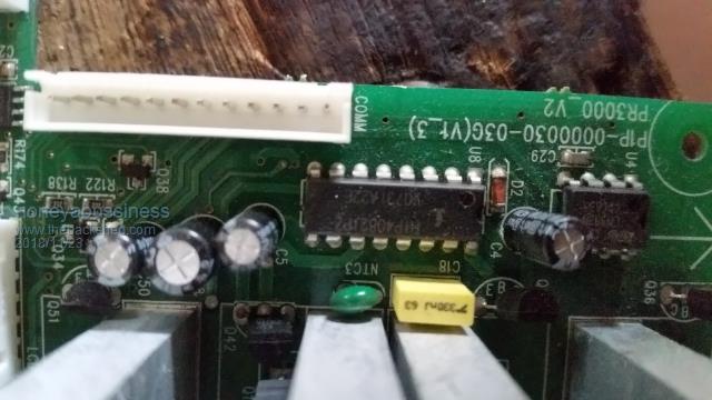
The outlay is almost 2 ir21844's together.. the inputs are all separate( "not gate" not needed but shown in datasheet), single resistor to set global dead time, and a short circuit current of 2.5 amp ish.(solar mike i don't understand the " no parallel issue you stated).. ive seen them happly driving 5+ mosfets ( similar to ir4110s etc.) In ups's that i dismantle quite regularly. .. it was purely a suggestion to simplify things.. I think it works !! |
||||
| noneyabussiness Guru Joined: 31/07/2017 Location: AustraliaPosts: 512 |
 Just to confirm what i said, in a cyber power 3kw UPS i pulled apart today... I think it works !! |
||||
| noneyabussiness Guru Joined: 31/07/2017 Location: AustraliaPosts: 512 |
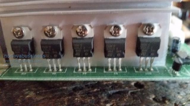
 The 5 per bank ( 4 of obviously ) mosfets it driving... sorry for blurring, stupid phone camera quits sometimes . Markings are p80nf10... I think it works !! |
||||
| wiseguy Guru Joined: 21/06/2018 Location: AustraliaPosts: 1156 |
No mainly into mini costs, the small pcbs are collateral damage with that  Tinker, make sure the RM6 cores are ungapped. You will also need to get the 2 small clips that hold the cores together. Use pins 1 & 2 for the 18T, 3&4,5&6,7&8 for the 20T windings. Suggest you use pins 1,3,5 & 7 as the start pins & wind always in the same direction. I have lots of these parts lying around so its essentially free for me I would expect the cost should be maybe 4 or 5 dollars. If you cant find cheap cores Ill send you a couple to play with. Also ensure you get the UCC3808 or UCC2808 version with a -2 in the part number they work from 4.5 - 14 volts, the other -1 types only work between 12 & 13 volts. The pin numbers on the schematic were for a premier magnetics core - prewound but too dear with freight added on. If at first you dont succeed, I suggest you avoid sky diving.... Cheers Mike |
||||
| Solar Mike Guru Joined: 08/02/2015 Location: New ZealandPosts: 1138 |
Hi noneyabussiness, that chip has pullup\down current of approx 1.4 amps according to its spec sheet. Yes this will drive some multiple low gate charge mosfets in parallel but not very well, the limited amperage capability means the switching time will be unduly long resulting in high power dissipation in the parallel devices. Many here are using the HY4008 mosfets, these each have approx 60 more nCoulomb's gate charge than the mosfets in your photo, this will make the situation much worse and switching times will be excessively slow. That manufacture is pushing the performance envelope using the chip as shown, unless there are some other hidden gate driver chips or totem pole driver transistors we cannot see. Cheers Mike |
||||
| wiseguy Guru Joined: 21/06/2018 Location: AustraliaPosts: 1156 |
Oops typo supposed to read 13 - 14V not 12 - 13. Noneya it was a good suggestion, but I agree with Solar Mike, The part also only has one ground pin which it shares with the logic inputs along with the gate drive high current return. Having separate pins for the high current return with an ability to not be affected with a few volts of difference between digital ground and output ground is an important feature of the IR family of half bridge drivers. If the 4081 is in close proximity to the bridge FETs on the same PCB helps to avoid issues. If at first you dont succeed, I suggest you avoid sky diving.... Cheers Mike |
||||
| poida Guru Joined: 02/02/2017 Location: AustraliaPosts: 1418 |
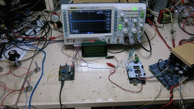
First, some answers: I asked Tinyt to accommodate 2 x IR21844 and one HIP4082 in the circuit and PCB. That way, either can be used on the same board. I have had some progress with nano2 code. So much so that I have a running prototype. It has fake AC volts, DC V, DC I and heatsink temp inputs which are driven by potentiometers. During testing I found a wrinkle. nano2 when booting pulls D7 down, low impedence. This is connected to nano1, D8 which is the on/off input. This means, during booting, nano2 will start the inverter, and nano2 code will think the inverter is OFF. What an awesome start to proceedings. So a change has been made, nano1 D8 pin will be: HOLD LOW = stop HOLD HIGH = run (the inverter) This now lets nano2 boot up without kicking the inverter into life unknowingly. I added a simple message displayed on the LCD on boot, for 2 seconds, to show it is booting and give me a cue to look for issues. I need to code some timeouts for the AC low level. Maybe later on tonight. No point in having AC output low level cut off active as soon as you start the inverter since the soft start will always trigger. And we won't get anywhere. I think a timeout of about 10 seconds after start will be suitable. I plan to permit either the old momentary push button or the current hold on/off to be used, switchable via #defines yet more video, do you find these worthwhile? I know I like to show the behavior of the code, to drive discussion of function and features. I have added support for toroid temperature, but since I have only Uno boards, I do not have access to ADC channel 7, where that temp sensor will be connected. It shows rubbish data now. Events in the video: start, DC V cut off, restart, heat sink temp increase, fan on (shown by star appearing), fan off (star disappears), increases to force cut off, restart and current increase to cut off. Values chosen are arbitrary. I do not care if they are wrong or poorly chosen. They are test values. Anybody can chose their own, and choose if any cut offs are active or not. mains sync was not active in this test. video code versions used: 2018-11-24_165611_nano2_1.ino.zip 2018-11-24_165638_nano_1_v3_sync_pid.ino.zip  wronger than a phone book full of wrong phone numbers |
||||
| Tinker Guru Joined: 07/11/2007 Location: AustraliaPosts: 1904 |
Wiseguy, I ordered the IC chip on ebay, found a plug in DIL version which I prefer. That RM 6 core, how critical is that? Could I substitute it with this core ? Can't find 8 pin RM6 at aliexpress, the 6 pin ones they have are too dear by the time postage and $AU conversion is added. RS comp. has them also but as they sell some parts as multiples this gets too expensive. I have an account with Altronics (they are just up the road) so the above core, if suitable, would do for an experiment making my very first switch mode supply. I have no problem with individual wires with the bobbin for that core. Klaus |
||||
| wiseguy Guru Joined: 21/06/2018 Location: AustraliaPosts: 1156 |
EEyuk ! Please dont use a pot core. try Here 1 or Here 2 or Here 3 Here 1 is an EP13 - first choice small and should be fine Here 2 is an EP17 - very suitable, a bit bigger, quite cheap (maybe go for these?) Here 3 is an EE16 - EE core should work ok 3d choice. If at first you dont succeed, I suggest you avoid sky diving.... Cheers Mike |
||||
renewableMark Guru Joined: 09/12/2017 Location: AustraliaPosts: 1678 |
Thanks for the video Poida and your hard work, you mentioned you only have uno's, I have plenty of nano's here and some digital temp sensors if you need them. I know how painful it is waiting for deliveries from China. Speaking of which am I safe to order the parts that were on Tinyt's last schematic? songle IR21844 TLP523 LM7812 LM7805 TLC2272 MAX232 Also connection for the gen would these bo OK? SSR RCBO Seems a shame to take the Mad control board off my unit since it has run non stop faultlessly running the house for almost 3 months, but hell this being able to snyc with a gen is a bloody ripper feature. If using this with Mad power board do all the parts on that stay the same? Cheers Caveman Mark Off grid eastern Melb |
||||
| johnmc Senior Member Joined: 21/01/2011 Location: AustraliaPosts: 282 |
Thanks Poida for the video information and effort that you have put into this project, also the schematics by Tinyt and suggestions by other members. Much appreciated by a electronically handicapped john . johnmc |
||||
| tinyt Guru Joined: 12/11/2017 Location: United StatesPosts: 438 |
After some 'heavenly guidance'. I have added the option to test the HIP4082, I still retained the IR2184 so that the three driver types can be tested. I don't know if I understood the HIP4082 datasheet correctly, so please review carefully. I have also added the SCR shutdown function, I don't know if it will work, or if I did it correctly. Here is the revised schematic for review and comments.2018-11-25_165412_NANOVERTERdraft13.pdf It is now in three pages. Have to rest my aching head now. |
||||
| noneyabussiness Guru Joined: 31/07/2017 Location: AustraliaPosts: 512 |
Please understand i only was suggesting that particular chip to simplify things. .. I think it works !! |
||||
| gaspo Regular Member Joined: 25/06/2018 Location: AustraliaPosts: 65 |
That SCR circuit is for the IR2110 with active high SD signal. The IR2184 has inverted SD, so you'll need to add NPN on the output to invert. |
||||