
|

|
Forum Index : Electronics : building an Inverter from scratch
| Author | Message | ||||
oztules Guru Joined: 26/07/2007 Location: AustraliaPosts: 1686 |
"So, does it work then? I hear somebody asking You bet it does." Thats what I have been waiting for. Do you have any clues what stopped you before from getting these results. It seems once you get one running properly, every next one you make works straight up. Mad had a run of outs too, and we still have no firm idea as to why. Now he cant seem to kill it from the looks. You do very nice work with a lot of time put in, wish I had your patience. Well done, a 6kw result, with plenty in reserve looking at the fet count and cooling. You have indeed been busy. ..........oztules Village idiot...or... just another hack out of his depth |
||||
| Warpspeed Guru Joined: 09/08/2007 Location: AustraliaPosts: 4406 |
An absolutely stunning result there Klaus, extremely professional! There has obviously been a huge amount of mechanical design work, time, thought, and know how go into this, and it really shows. Most impressive. I still have not purchased a digital camera, and have been thinking about the problem of focusing small objects up close, particularly PCBs and CRO screen. The solution to this might be a document camera. A good one can focus on objects from postage stamp size up to maybe A4 sheet and produce a nice crisp high resolution image. Previous experience with one of these suggest the depth of field is not great, but perfectly adequate for a circuit board or single small objects. Never tried it with an oscilloscope, but see no reason why it should not work well with that too. Cheers, Tony. |
||||
| Warpspeed Guru Joined: 09/08/2007 Location: AustraliaPosts: 4406 |
One question Klaus, how did you cut the heatsink ? My best efforts in that direction so, far have been with a brand new (and very sharp) tungsten tipped panel saw blade, one with the largest number of small teeth, and lots of WD40 as a cutting lubricant. Cutting aluminium will totally destroy the blade in two or three cuts, but as the blades are not that expensive, a new blade will be junk after a job like this. Best to buy a couple of blades... There will be a blizzard of aluminium chips that fly everywhere, so its best done outside. Cheers, Tony. |
||||
Madness Guru Joined: 08/10/2011 Location: AustraliaPosts: 2498 |
There are blades made for aluminum, it is not just the number of teeth. However, I have cut the heatsinks with a reasonable quality wood blade that cost about $80 with no damage to the blade. You do need to ensure the workpiece remains in the same angle in relation to the blade, I used a fixed guide on both sides. There are only 10 types of people in the world: those who understand binary, and those who don't. |
||||
| Warpspeed Guru Joined: 09/08/2007 Location: AustraliaPosts: 4406 |
The blades I used were tungsten tipped cheapies from Bunnings, less than $20 as I recall. I have burned down several, but its not an expensive ewxercise if you are only doing one job. The aluminium suppliers like Alcan cut thick extrusions with heavy blades made from tool steel, similar to blades used in a steel cutting cold saw. These are definitely not low cost blades. And it definitely needs a rigid saw guide, or a proper table saw bench. I have had success with clamping heavy metal angle to the heatsink with large G clamps, being very careful to get everything straight and square. That will guide a hand saw straight and true. With a bit of patience setting it all up, and plenty of cutting lubricant, a good result is not that difficult to achieve. My efforts with a small band saw have not been encouraging. The blade guides need to be set far apart because of the bulk of the heatsink, and the blade bows and wanders leaving a very ragged cut. Cheers, Tony. |
||||
| yahoo2 Guru Joined: 05/04/2011 Location: AustraliaPosts: 1166 |
It only takes one largish job to justify a metal cutting bandsaw. After that it pretty much gets used for everything metal. If the blade guide bearings are very cheap (loose) we toss them and replace with average ones. Once the blade guide is tweaked to run straight and square it seems to stay on track. saves a lot of time and material. Can even slice shims and washers for those one-off jobs. It would be better with a 3 phase motor and speed control for aluminium but it works fine as it is. Really nice build klaus. I'm confused, no wait... maybe I'm not... |
||||
| Tinker Guru Joined: 07/11/2007 Location: AustraliaPosts: 1904 |
Thanks for the kind words. Sorry to say that a metal cutting bandsaw would do nowhere near as good a job with this heat sink as a circular saw with a reverse angle teeth alu cutting blade. I do have a metal cutting band saw and there is no way the cut is smooth enough for what I required... So one needed a milling machine to smooth it and I don't have one. Klaus |
||||
| Tinker Guru Joined: 07/11/2007 Location: AustraliaPosts: 1904 |
Oztules, I think we can best call it 'senior moments'   when defining the reason for that many failures. when defining the reason for that many failures.Unfortunately I get a bit exited when something is finished and am way too keen to switch it on, when I really should triple check everything first. Then, learned the hard way, this inverter *MUST* be soft started, every time something has been changed.... Lastly, but not sure, the new 8010 board has a ground plane. The others were just single sided home etched boards. Now I will be busy for a while to make an enclosure for it, a decent looking one this time. Thanks to everybody contributing their valuable knowledge and get me up to speed with this project. Anybody starting up an inverter build would do well reading all 38 pages of this thread and thus, perhaps, avoid some of my mistakes. Klaus |
||||
| Tinker Guru Joined: 07/11/2007 Location: AustraliaPosts: 1904 |
Some more testing today. This time with a 3KW load for a longer period, to see if something gets warm. My solar charging today was only 2.2KW during this test so I did not like to run a bigger load. Anyway, this is the 3KW CRO trace now: 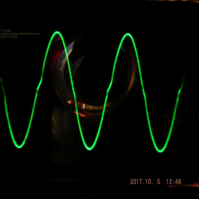 I'm happy with that and it appears the extra choke I connected into the other primary leg does help. So now it has the ferrite 4 turn choke (52.5uH) in one leg and the converted small Aerosharp choke (36uH) in the other leg. If anybody is interested how to convert that Aerosharp choke let me know, I took some pics. Total idle power (with LED power display) is now 38W, of which 29W are the magnetising losses. And the heatsink did not get warm at all. So the over 8000sq cm of fin area are well up to the job and the 92mm fan fitted to the end of the heat sinks will have an easy life. Can't wait to put the lot into the enclosure and see if the fan comes on at all  . There will be a 120mm mains exhaust fan as well, triggered by its own temperature relay. . There will be a 120mm mains exhaust fan as well, triggered by its own temperature relay.Warpspeed made the following comment elsewhere: "I had a home built inverter that ran for a couple of years without any problem, then suddenly spectacularly blew up, and kept blowing up randomly after replacing several sets of mosfets and gate driver chips. It took me quite a while to discover why. The quartz crystal metal can was intermittently shorting to the pads on the circuit board directly underneath. Fitting an insulating spacer between crystal and PCB fixed that problem." Thank you, thank you   for mentioning that, it might have averted another unexpected disaster. for mentioning that, it might have averted another unexpected disaster.I looked at a spare 1810 board and, sure enough, the pads under the crystal were bigger than the clearance around the crystal pins. I do not like too small pads and prefer 1mm holes in them, makes it easier to swap a component without destroying the PCB. So I unsoldered the crystal and fitted a spacer (a section of TO220 mica insulator with two pin holes punched through). While this board worked OK it was a bit of a time bomb, the metal case of the Xtal was really close to the board surface. Thanks again Warpspeed for this tip, it never occurred to me that could happen  . .Klaus |
||||
| Warpspeed Guru Joined: 09/08/2007 Location: AustraliaPosts: 4406 |
It never occurred to me either.... until it happened. Anyhow You can buy the proper crystal spacers from e-bay. These are nice thick molded plastic spacers. http://www.ebay.com.au/itm/100pc-TQ-06-Crystal-Oscilator-Insulator-Washer-11-2x5-0x1-0mm-PG-HC-49S-HC-49/130871999210?ss PageName=STRK%3AMEBIDX%3AIT&_trksid=p2060353.m2749.l2649 Cheers, Tony. |
||||
| Tinker Guru Joined: 07/11/2007 Location: AustraliaPosts: 1904 |
Having my inverter all in bits at the moment - I'm making a cabinet for it - I thought to do some testing with regard to the capacitor that needs to be placed across the secondary of the toroid transformer. I did use warpspeeds 75Hz resonance method and thought 3uf were about right but its rather hard to see the resonance peak on the scope and I do not have a spectrum analyzer... So I connected my variac to the primary winding and slowly wound up the knob until there were 235VAC on the secondary. The primary current was measured for these tests. Interesting results: 25VAC into primary gave 235VAC out of the secondary, primary current with no cap was 1.06A 0.68uF cap = 1.00A, secondary now 237VAC 2 x 0.68uF caps = 1.00A and similar voltage 1x 0.68uf + 1x 1.0uF parallel = 0.99A, 238V 1x 0.68uF + 1x 2.2uF parallel = 1.5A Adding capacitance after that = bigger primary current. I tested up to 4.7uF. So it seems for my toroid the sweet spot is 1.0uF + 0.68uF caps if the aim is to keep the idle current low. Perhaps warpspeed might comment if there is any science behind this method. Its certainly easier to do than the resonance method. Once I re assemble my inverter I will test my various chokes with that new 1.68uF capacitor combination. I used the grey 300VAC rated caps salvaged from the aerosharps. Klaus |
||||
| Warpspeed Guru Joined: 09/08/2007 Location: AustraliaPosts: 4406 |
The most "efficient" frequency would probably be to resonate at exactly 50Hz. The problem with doing that, is under zero load the inverter output voltage might tend to go very high. There will be a resonant buildup of energy that the feedback might not be able to cope with. Rather like the tuned tank circuit in an unloaded radio transmitter... Testing with a variac, the transformer is always coupled indirectly back into the grid, and you are just measuring the current flowing in and out. When driven just by the inverter, with no other load connected, the voltage may possibly "run away" if the transformer is strongly resonant at exactly 50 Hz. That may be a problem, or it may not. The advantage of choosing 75Hz is that any stored resonant energy will be out of phase with the following cycle, and tends to be damped out. It will still make a very effective filter at the PWM switching frequency. And it should reduce any faint wobbles that may be slightly visible if the natural transformer self resonance is in the low Khz range. So really, adding a capacitor is likely to clean up the waveform, and the more capacitance the more effective the filtering. But a strong 50Hz resonance may potentially present a problem and is best avoided. This is mostly speculation and theory and trying to understand what what the commercial inverter guys have done, and try to understand why they did it that way. Reverse engineering if you like. But its substitute for doing your own actual testing. Cheers, Tony. |
||||
| Tinker Guru Joined: 07/11/2007 Location: AustraliaPosts: 1904 |
Thanks for that detailed information. Just to clear one thing, my variac always has an isolation (1:1) transformer between it and the grid, which in this case is my other LF inverter that runs the house. But you can be assured that I will do more experiments with that secondary capacitor once the primary is again exited by the 48v battery. I though it was curious how big a difference the caps made to the standby current. With my inverters they will never run with *no* load, there is always 50W or so drawn by things in my house that are kept plugged in but not turned on to work. Klaus |
||||
| Warpspeed Guru Joined: 09/08/2007 Location: AustraliaPosts: 4406 |
The idling power required to drive that toroid has three main components. Eddy current loss in the core, which is resistive in nature and in phase with the voltage. Hysteresis loss which is highest during the voltage zero crossings when there is greatest rate of change of the magnetic flux, which appears inductive in nature. Both of these are due to the properties of the iron core, which we can do nothing about, and both are frequency dependent. An air core would have neither of these losses. The third is the pure reactance Xl which is the true value of inductance. This stores and releases out of phase reactive power each quarter cycle. The higher Xl is, the less load it places upon the driving source. We can cancel this out by resonating Xl with Xc in parallel, and make the combination have a higher combined parallel impedance at the resonant frequency. How well this resonance works depends mainly on the resistive loss of the inductor, or circuit Q. If the combined resistive loss is very low we might see a big dip in idling power when we resonate that inductor. If the whole thing is much more lossy, we still might see a slight dip in required drive power around resonance. So when we get close to resonance, expect to see a slight increase in impedance and a slight reduced idling power. Probably not a huge difference, but quite noticeable. As we keep increasing the shunt capacitance below resonance the impedance the whole thing then becomes capacitive with a lower Xc impedance. Something we definitely don't want. So the optimum shunt capacitance across the toroid is probably something fairly close to but just above resonance. Cheers, Tony. |
||||
| Tinker Guru Joined: 07/11/2007 Location: AustraliaPosts: 1904 |
A spare batch of HY4008 Mosfets arrived today so I tested them and sorted into similar Rdson values. 40 items ranged from 2.83mOhm to 2.95mOhm. For those who are new to selecting the mosfets to be connected in parallel - I select mine to be within 0.01mOhm (0.00001Ohm)- here is a picture of my test rig: 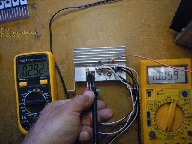 I use a beefy power supply (>300W) to pass 10Amps through a low value (~2 Ohm) high watt resistor. My resistor is rated about 100Watts, if only a smaller wattage is available perhaps dunking into a bowl full of water might keep it cool. The Mosfet is mounted on a recycled piece of heat sink for mechanical reasons and, more important, for the drain current to flow via the heat sink. There is a screw terminal connecting the gate and source pins only. This is quick to do and reliable contact wise. The gate is driven from 12V via the usual gate resistor/diode arrangement. The power supply is adjusted for near enough to 10Amps (my power supply does not adjust fine enough with that size current)to flow in the series resistor/ drain/ source circuit. Now the *very* important part is to place the probes of a milliVolt meter right against where the center pin (drain) and source pin enters the Mosfet body. Even just a millimeter off at the source leg gives enough voltage drop to make the readings inconsistent. A similar current, close to 10A, should flow for each measurement and the meter probes be placed exactly at the same location for each Mosfet test. On the mV meter the decimal point is mentally shifted to the left by one digit (2.92mV) and then the display reads in milli Ohms directly. That is why I used 10 Amps test current in the first place. Here is a pic of the m Ohm values arranged in rows, lowest on top, highest on the bottom. 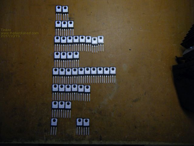 Klaus |
||||
| nickskethisniks Guru Joined: 17/10/2017 Location: BelgiumPosts: 458 |
Is there someone that has a good source for laminated iron toroidal cores in Europe? I have 3 isolation transformers of 2000VA, each 16.5kg, how much power could I expect if I stack them together? Could I gain power or will it stay at 6000VA? At 230V they idle around 20W each, they are wounded with 1.3V/turn. Could that be better? http://www.amplimo.nl/images/downloads/ds%20standardrange/n8670pt.pdf I don't know if I want to sacrifice them yet ... |
||||
| Clockmanfr Guru Joined: 23/10/2015 Location: FrancePosts: 429 |
Hi nickskethisniks, Essayez de contacter 'Rhume' avec un message personnel du forum, il est un membre du forum, il est également de Belgique Je pense qu'il a une source belge pour les tores toroïdaux. Try contacting 'Rhume' with a forum personal message, he is a forum member, he is also from Belgium. I think he has a toroid core material source there in Belgium. Everything is possible, just give me time. 3 HughP's 3.7m Wind T's (14 years). 5kW PV on 3 Trackers, (10 yrs). 21kW PV AC coupled SH GTI's. OzInverter created Grid. 1300ah 48v. |
||||
| Tinker Guru Joined: 07/11/2007 Location: AustraliaPosts: 1904 |
OK folks, the time has come to slowly wrap up this thread. At 39 pages and close to 1/4 million views must be something of a record on this forum. Anyway, the individual parts of my inverter have been thoroughly tested and perform as expected. So what remains is to place everything into a suitable enclosure to get a useful inverter. I did tinker with a commercial metal toolbox which, while big enough, was made from just too flimsy metal to support those rather heavy parts inside. So I decided to make my own enclosure, this way I get something with exactly the right dimensions and the freedom to place parts where I want them located. How hard can it be? Not really difficult as it turned out, if one can do a bit of metal bashing. This is what I came up with: An angle iron frame and a stack of brackets. 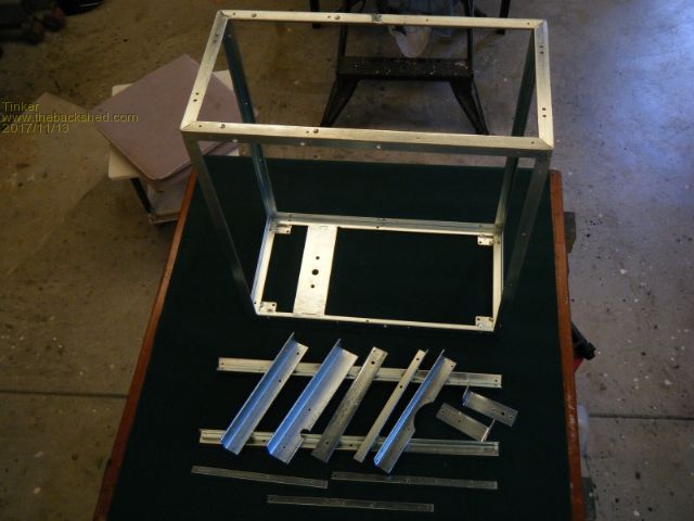 Putting it all together it looks like this: 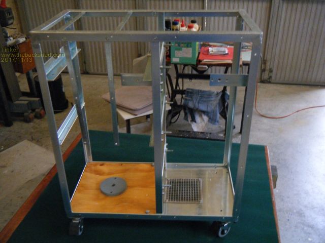 And then fitting all the parts inside. Several pictures from various angles follow: 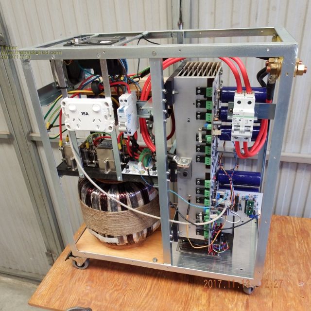 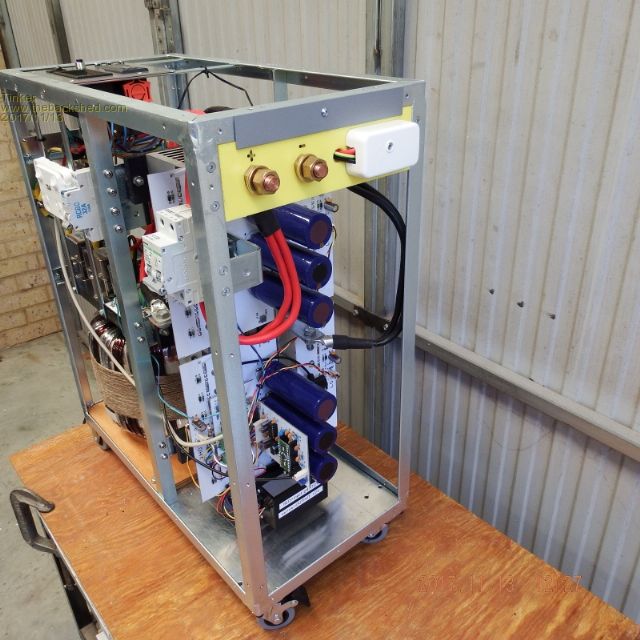 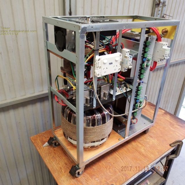 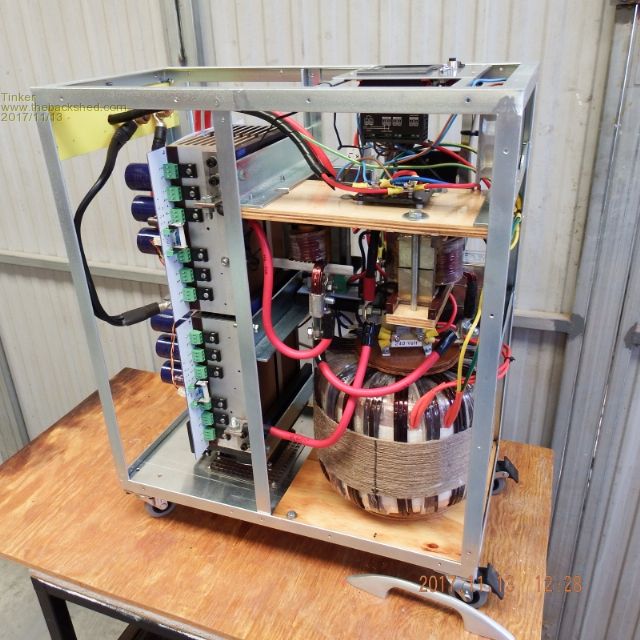 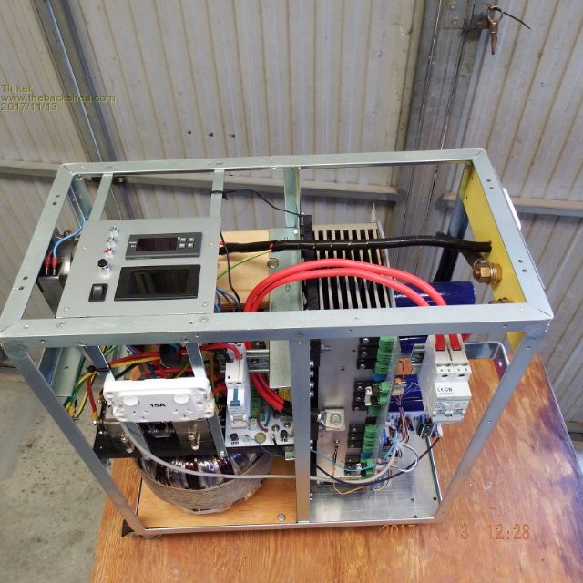 As you can see I made it service friendly. All parts are attached to the frame so the unit can be powered up and tested with the front & side/ back & side cover panels removed for complete access to everything inside the inverter. I learned this necessity the hard way when stuffing too many parts of my PJ inverter into a 3KW Aerosharp box... So all that remains is to turn it on. Idle power is 33W for the lot, about on par for a dual stack toroid core. The idle wave form looks like this: 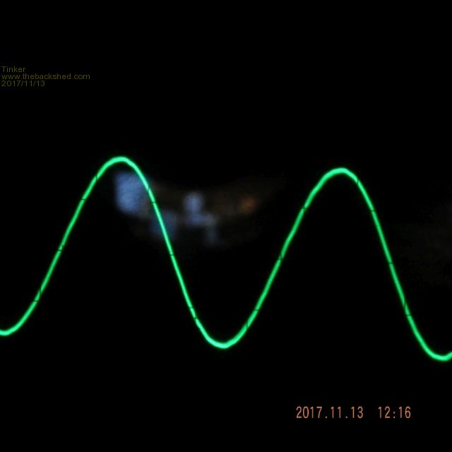 Then I started connecting loads, 2 kettles, 2.4KW fan heater & 6 flood lights. This is how far I went: 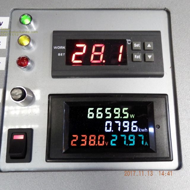 My clamp meter measured 150Amps drawn from my 54V battery bank, as much as I dared, the bank has 150A breakers fitted. The corresponding wave form looks like this: 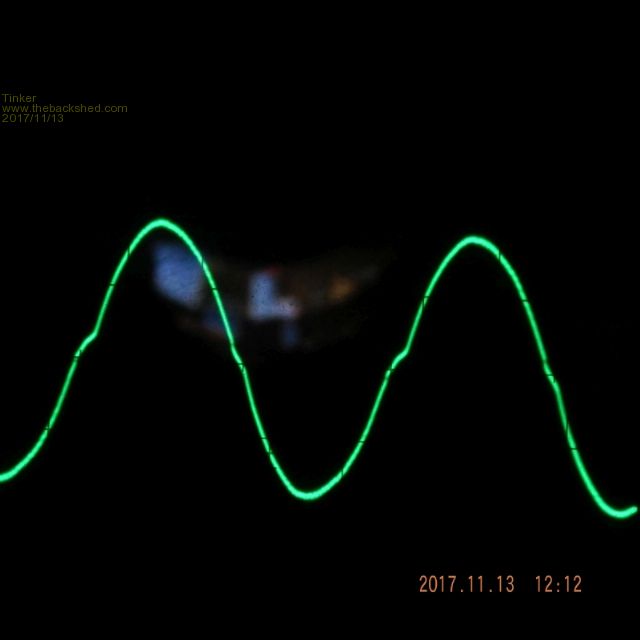 At idle this inverter is absolutely silent and at 6KW+ load there was a low growl which was just about drowned out by the noise of the fan heater load. I'm happy with that  And the fans never came on at all. It really pays to fit a decent size heat sink and orient it in the enclosure so natural convection does a lot of the heat transfer. This is the size comparison to the 3KW Aerosharp box, mounted above: 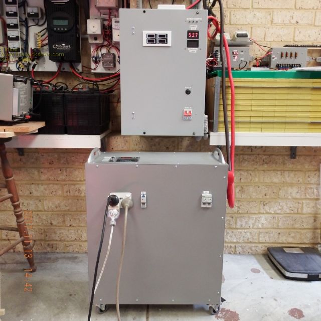 My enclosure has a similar height and depth of the Aerosharp but it is wider of course. I was glad I decided early on to mount it on castors (lockable) as the monster weighed in at 55kg - far too heavy to hang on the wall. Now, what's left is some more testing to see how warm that enclosure gets inside and doing 2-3KW endurance loads when there is lots of solar input to keep up the battery bank charged. Then it will go into service, powering my house. I had posted circuit diagrams along these pages, those who followed this marathon thread might have noticed that there were changes in them and my final inverter is no exception. Anybody interested to see the latest diagrams please ask. Naturally, what has finally worked out well for me might have an equally long road to success for others...  Klaus |
||||
| Warpspeed Guru Joined: 09/08/2007 Location: AustraliaPosts: 4406 |
Klaus, that is definitely a thing of great beauty. A truly great effort and something to be really proud of. Cheers, Tony. |
||||
oztules Guru Joined: 26/07/2007 Location: AustraliaPosts: 1686 |
Well done..... they really do work  Brilliant workmanship, I don't have that patience. .........oztules Village idiot...or... just another hack out of his depth |
||||