
|

|
Forum Index : Electronics : Inverter building using Wiseguys Power board and the Nano drive board
| Author | Message | ||||
| bret76 Newbie Joined: 03/02/2023 Location: FrancePosts: 18 |
Sorry, I got stuck on the operation of the L+C. I tried to simulate with a LT spice 1/4 of a sinuzoid (1/4 of 50Hz): - in red a perfect sinuzoid for comparison for the shape (the voltage values are not correct because they depend on the battery, the transformer, the pwm...). - in green / upper curve the voltage at low load (R=100). We can see that it ripples a little. It does it more or less depending on the L+C values. @KeepIS: can you confirm that at low load, you find this ripple? I want to make sure that my calculations are not too wrong vs reality? - in green / lower curve, the voltage under heavy load (R=0.2). We can see that it shifts from the sinuzoid, especially at the beginning. Maybe an idea to explore: tinker with the PWM signal to slightly increase the PWM signal duration on the 0/3µs range. 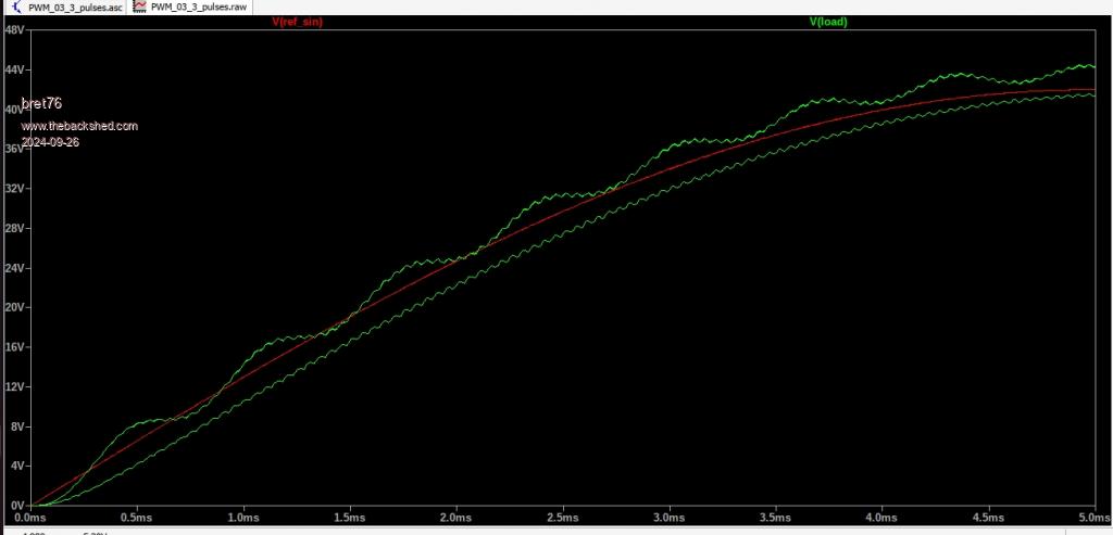 For those who would like to try, it's interresting, because the software can extract voltage, current, power, fft, harmonic distortion.... We can therefore have an idea of the evolution of the no-load power or the distortion vs. the value of L+C+load. 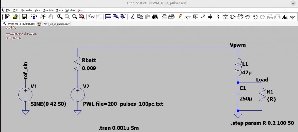 If I'm off topic, feel free to tell me! David |
||||
| KeepIS Guru Joined: 13/10/2014 Location: AustraliaPosts: 1679 |
If you are looking for a simulation for the AC output from my inverter, then you have not included the dual stage AC filter that's in the Inverter. Unfortunately I can't access the input to the AC filters, at least not without removing the filters and undoing a very large double terminal block. Obviously you will see some spwm ripple at the AC output before the filter, but the level varies with so many variables in an actual running inverter. Sharp transient Switching Harmonics are also mixed in along with Power stage DC ripple and resulting waveform distortions. All influenced by FET switching speeds, power stage Filtering layout and values, cabling interactions and coupling effects ETC. When I get a chance, I can set up my "Inverter Test JIG" with that value of Choke and post a Capture for you if that will help you with what you are trying to achieve or verify. I have seen the slight ripple in the lower trace which is quite common, but I doubt that anyone is going to look any further into SPWM generation for a "possible" minor or simulated imperfection in this powerful and proven design. I just had a look at the AC output of the Inverter (running the House and workshop), using a TekTronix 100Mhz DSO. With part of the sinewave zoomed in to almost a straight line across the display, as I zoomed in, there was nothing but the finest step appearance when fully zoomed in, which could be just the limited resolution of this Tek DSO at that zoom level. This is a capture of the Dual Inverter output with a few kW of load using a 340Mhz RIGOL DSO 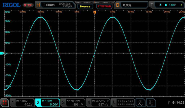 Edited 2024-09-26 09:49 by KeepIS It's all too hard. Mike. |
||||
| bret76 Newbie Joined: 03/02/2023 Location: FrancePosts: 18 |
Indeed, I missed the EPCOS filter. When I read your story, I didn't understand its usefulness. To understand better, I removed everything that did not seem useless to me.  Now I understand their importance better!  So I'll have to put some in too. Above all, don't modify your inverter, it's much easier for me to change the simulation if necessary (a few clicks and it's done)! David |
||||
| poida Guru Joined: 02/02/2017 Location: AustraliaPosts: 1418 |
KeepIS: that is better than mains. wronger than a phone book full of wrong phone numbers |
||||
| nickskethisniks Guru Joined: 17/10/2017 Location: BelgiumPosts: 458 |
Your simulation confirms my dso images when probing a hf inverter (hv bridge and lc filter). In a lf inverter some magic hapens in the transformer. So you will need to take that in to account as well. |
||||
| KeepIS Guru Joined: 13/10/2014 Location: AustraliaPosts: 1679 |
Even with bad loads the waveforms still looks like the Mains under the same loads, and now feels like I'm on the Mains AC in this Dual Inverter. The combination of two powerful power-boards and Toroids, with your proven SPWM generator code running on a Nano module and wiseguys designs, are simply brilliant  I'm sure both of you are sick of hearing that  The Nano module itself has proven 100% reliable, not a single issue or unwanted behavior of any kind under normal running and my absolutely abusive testing. Given the low cost of a Nano module, any thoughts that it might prove to be a slight weak spot in a high power Inverter have been completely vanquished IMHO. _ Edited 2024-09-27 11:59 by KeepIS It's all too hard. Mike. |
||||
| Cpoc Regular Member Joined: 28/05/2024 Location: PortugalPosts: 78 |
Looking forward to building mine with this proven design. I will soon start buying up all the required parts needed for my builds. A big THANK YOU to ALL the devs involved.  |
||||
| bret76 Newbie Joined: 03/02/2023 Location: FrancePosts: 18 |
Do you have any idea of the remaining uH in the inductors when you are at full power? (50% of the initial value ? -> something about 20µH in total?) Many saturation tests have been done, we often talk about the inductance at no load (indicative value?), or the Amps at the knee, but not so much of µH remaining under load (useful value?). I understand that the inductor is used to protect the MOFSETS from currents that are too high when the current is at its maximum. My goal is to avoid ending up with an inductor that doesn't have enough µH under load (as I planned to buy bigger cores Like MS-301060 ones - which should reduce the number of cores and the heating a little (I hope !). David |
||||
| KeepIS Guru Joined: 13/10/2014 Location: AustraliaPosts: 1679 |
The only heat using sendust cores appears to be from winding resistance, and again, I purposely use smaller gauge cable for chokes in order to have a small resistive loss. Two chokes and one Toriod have survived for a year starting AC loads surges up to 18kW many times a day, those loads are now halved across four chokes, two Toriods and two power stages. I did "roughly" calculate remaining inductance at one time, from memory around 9uH, but that was for a single 8 or 9 stacked core 43uH choke. A number of posts and discussions have been had looking at remaining inductance at expected full load currents. From my first ever Inverter build, I had decided to add an "insurance policy" of a small resistive loss between the FETs and the Toriods to help ease any possible saturation or unmeasured/unknown interaction between the FETS and a Massive Toroid under certain complex load conditions. Years ago, builders found when a small resistive loss was inserted at that point in the Inverter, it was enough to help or eliminate some otherwise unexplained FET failures they were having. Back then chokes were being wound with a few turns of 0-Gauge cable on a ferrite core, which saturates if you look sideways at it, works great at idle though. . Edited 2024-10-03 14:06 by KeepIS It's all too hard. Mike. |
||||
| bret76 Newbie Joined: 03/02/2023 Location: FrancePosts: 18 |
I just did a quick calculation (R mosfets + R cable), you are almost at "Pulsed Drain Current" ! Whaoo !! That is safety, but without the straps  . Good done ! . Good done !Maybe some low and narrow pulses are missing in some conditions (1 pulse missing => 2xI , 2 pulse missing =>3xI), leading to I increase => µH decrease / saturate => more I ... Red : normal current over inductance Purpule : current if low pulse is missing 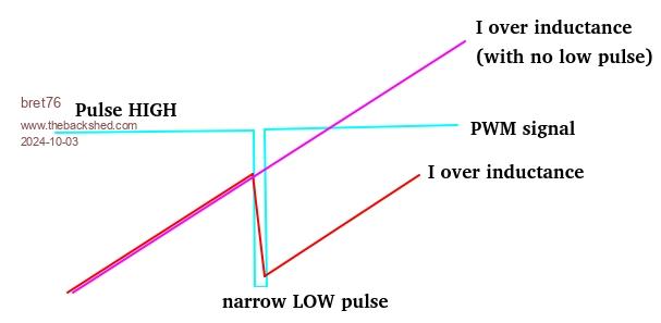 Luckily you explained it to me, I was going to do the opposite (put a big cable in the inductor to reduce the heating)  |
||||
| KeepIS Guru Joined: 13/10/2014 Location: AustraliaPosts: 1679 |
I had a question about setting up "Tera Term" Terminal program to work with Nano Menu system in my Code, and another about setting up YAT. So the easy one is Tera Term, In Setup -> Terminal, set New Line for RX and TX = LF, Terminal ID is VT100, Local echo can be on or off. YAT: Note: I spent all of two minuted on this Terminal program, I have not used it before, just checking it worked correctly, so I'm not really interested if something is incompatible with your YAT religious or other technical manta. After this very brief look at YAT, I do like the program and will look at it in more detail when I get time. Screen Grab for YAT: Terminal. 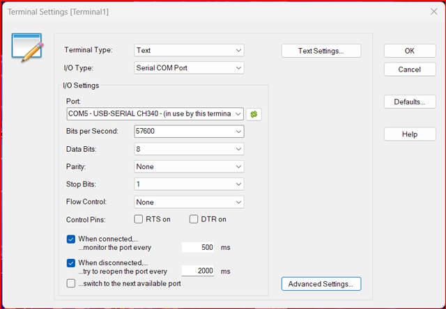 Text Settings. 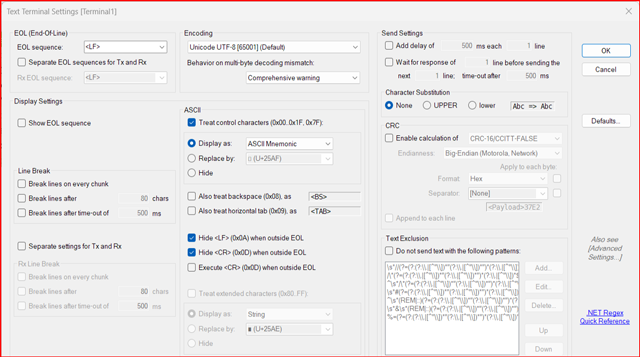 Advanced Settings. 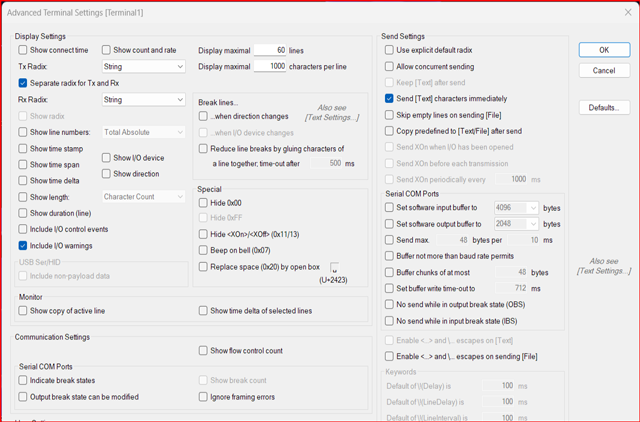 Inverter update The Inverter is still running perfectly, about a week ago I re-terminated the Dual AC output cabling and correctly matched the lenght of each output to the combining block, so it's now almost impossible to see any difference in load sharing between the two Power and Toroid stages. I've had the inverter hovering around 9kW and it's simply effortless. My solar cannot keep up, batteries are fine, but an hour with overcast rain and little Solar will see them down to 80% at that varying power level, but that's something we would never do if we needed to conserve power. (I'm only charging the LFE batteries to 90%) Obviously the extra 20 watts consumed by the second power stage and Toriod cannot be seen in normal overnight running. Why is it only 20 watts when I'm running a total of 48 watts idle? Because 8 watts is used for the meters, assisted low speed convection flow, power supplies, LEDs, relays etc. The idle power of one Stage is 28 watts, but the magnetizing power + power stage of each is around 20 watts - 28+20 = ? _ Edited 2024-10-14 13:26 by KeepIS It's all too hard. Mike. |
||||
| -dex- Regular Member Joined: 11/01/2024 Location: PolandPosts: 99 |
It seems to me that you would be one of the few people who could fully use the potential of these large cores. I checked how much it would cost to send them from Poland to Australia - twice as much as their value + customs duties and taxes. |
||||
| KeepIS Guru Joined: 13/10/2014 Location: AustraliaPosts: 1679 |
Hi Dex, I've been away for a weeks holiday at the beach, just unpacked and back at the PC. Yes, I would have liked testing those, having said that, this new inverter with four big chokes is more then capable of handling anything that I can throw at it, running 24-7 and I still have not had a toroid fan start. Just inverter silence. Like you, Amateur radio suffers a bit, mainly from the Solar regulators. The Inverter has some noise, but I have not had the time to try and reduce it, and it does not stop me from being on Air. However, the "Make Sky Blue" Solar chargers are a real problem, especially at high power output and make amateur radio almost impossible. _ Edited 2024-11-02 13:43 by KeepIS It's all too hard. Mike. |
||||
| nickskethisniks Guru Joined: 17/10/2017 Location: BelgiumPosts: 458 |
Buck converters tend to be very noisy on there input. Also, it might be the ringing of the mosfets that's causing some emi problems, some simple rc snubbers could help remove some of that noise. |
||||
| KeepIS Guru Joined: 13/10/2014 Location: AustraliaPosts: 1679 |
I fully understand the cause of RFI and Inverter noise sources, both buck and boost, that's the easy part, however reducing radiated RFI is a seriously time consuming and frustrating endeavor in large high power systems with multiple SM devices. Especially when RFI is low enough to not impact normal domestic radio and TV signals. However Amateur radio covers the spectrum of VLF LF, HF, VHF, UHF and SHF, with various modulation modes and bandwidths, usually with very sensitive equipment and high gain antennas. Sometimes reducing EMI to levels compatible with nearby receiving equipment is simply not possible. In many cases it's not even worth the effort for those of us with an Amateur license in suburban areas, we are now surrounded by dozens of solar systems and an array of crappy RFI generating GTI devices, and houses full of RFI generators disguised as TV's, microwaves, fridges and small SMPS devices   FYI My current Nano Hex version 7.7. Link to Nano Hex file zip This link is always updated with the Latest Version, it includes Single and Dual inverter versions, however both versions work in a dual toroid inverter - see "Latest changes.txt" in the Zip download for using ADC-7 in the Dual code version. _ Edited 2024-11-03 16:20 by KeepIS Footnote added 2024-11-04 17:46 by KeepIS Edited "Latest changes" file to clarify V7.7 and V7.6 info. _ It's all too hard. Mike. |
||||