
|

|
Forum Index : Electronics : Hopefully? Another 48vdc-240vac Toriod Inverter build.
| Author | Message | ||||
| KeepIS Guru Joined: 13/10/2014 Location: AustraliaPosts: 1679 |
A lot has happened with the inverter, we had a failure staring a big load, however there was no visible damage to anything except for D16, one of the MUR420 Diodes. Wiseguy designed the Power board for 5kW continuous and peaks of 10kW: I have peaks starting currents above that and when you have a few workshop induction motors running, and then start another peice of equipment that causes the over current trip just has the new load is spinning up, well I would not like to see the sort of collapsing fields and back EMF that would have been presented to the Toriod from those induction motors spinning down. As Mike [Wiseguy] pointed out concerning D16 failure: "The MUR420 diodes were there to save some heating of the FETs internal diodes, at the time the FETs were going to be HY4008, however I am using HY5608s. The HY5608s essentially run cold but with high currents their increasing forward voltage drop which can be as high as 1.3V @ 180A would then force excess current through the MUR420s which I think is what killed D16. There is no data I could find about the peak HY5608s forward current but it is stated as 360A continuous, a slight upgrade from the 4A & 110A absolute peak of the MUR420. The HY5608 FETs forward current is also 360A continuous and ~ 1290A peak, I would expect the peak diode current to be at least ~ 1000A" The Diode spilled it's guts and blackened 20mm area under and around the Diode, a quick rub with PCB cleaner and the PCB was like new. The FETs were physically as new, however that diode would be a dead short to the upper FETs and two on the upper and two of the lower FETs on one side were shorted. It took all of 20 minutes to have it repaired and bench tested: Now all of this happened just as I had finished building the New version "untried" Controller board that Wiseguy had ordered, I'm glad that I had nor rushed putting in in the inverter, otherwise it would have been blamed for the Failure. The new controller was tested on the bench driving the newly repaired Power board, and it worked with my test Toriod setup, so it was all put into the inverter. So, the inverter is up and running again: At the same time my new RIGOL DSO arrived and a Differential Probe a day later, and it's always a bad thing when I get a new toys to play with. 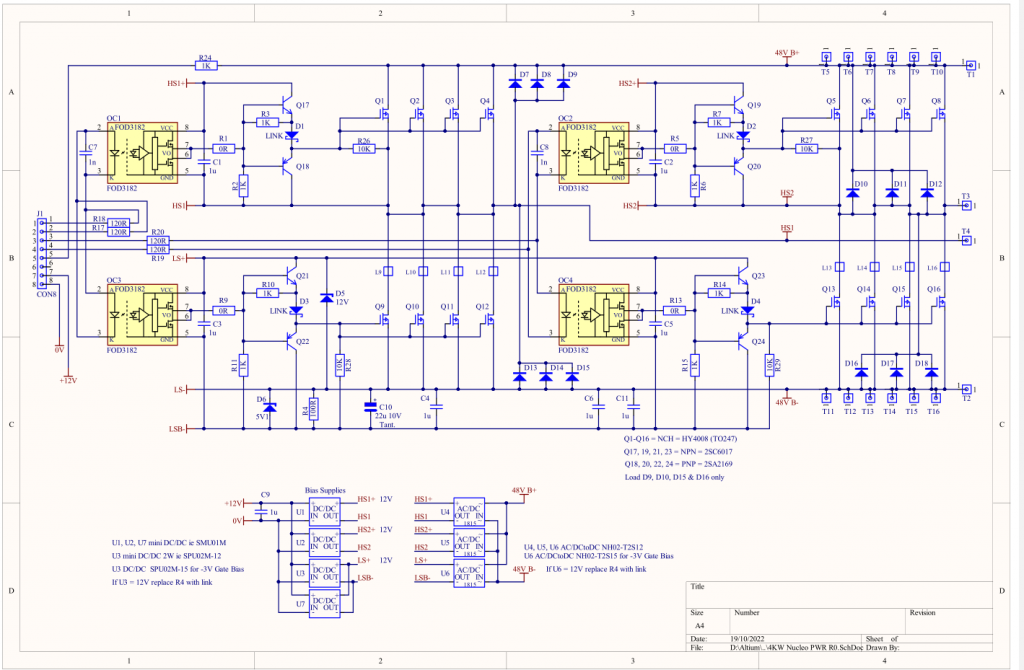 . It's all too hard. Mike. |
||||
| KeepIS Guru Joined: 13/10/2014 Location: AustraliaPosts: 1679 |
A question I have is regarding the long period of ZERO PWM between the HI and LO side PWM. Some of the noise is due to DSO Probes connections. Here is the output from T3 and T4, both referenced to T2 which is 48V B-. Blue is AC out. 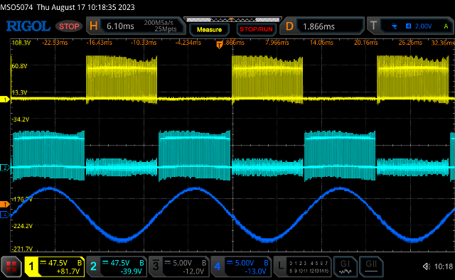 Now here is the PWM zoomed in: There is around 230uS between the last PWM pulse on the upper side and the start of the first PWM pulse on the lower. 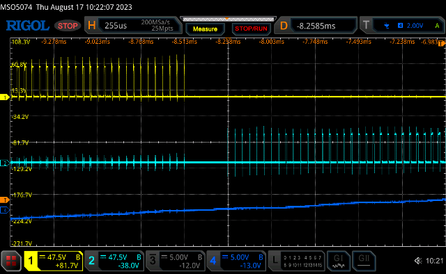 . It's all too hard. Mike. |
||||
| KeepIS Guru Joined: 13/10/2014 Location: AustraliaPosts: 1679 |
FYI The New Test controller circuit. 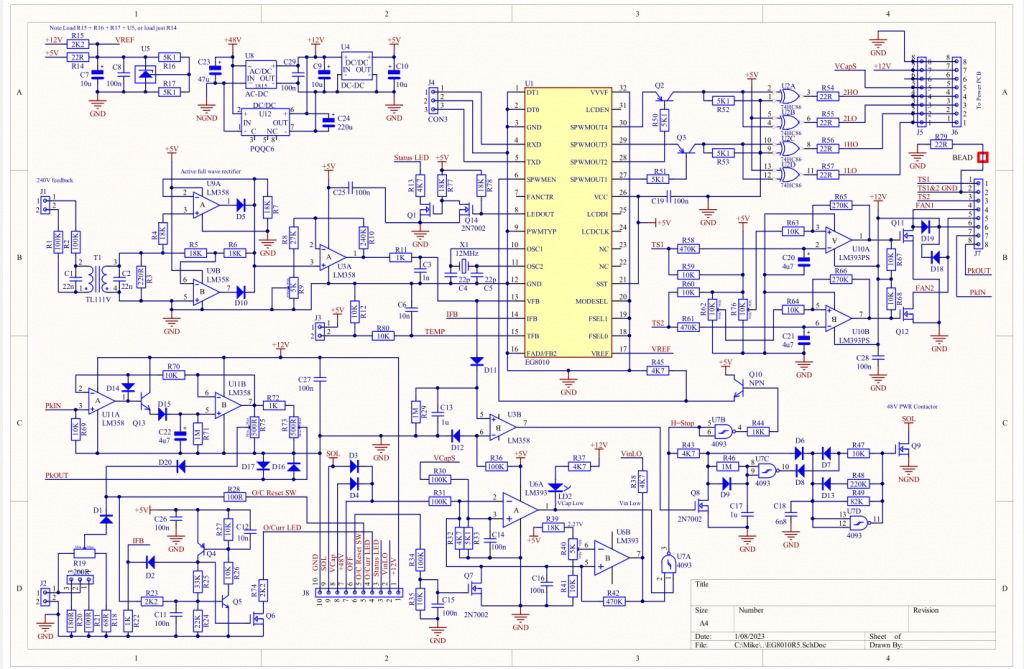 . It's all too hard. Mike. |
||||
| Godoh Guru Joined: 26/09/2020 Location: AustraliaPosts: 458 |
Sounds to me that you are asking a lot from your inverter. To try and run induction motors and also start others at the same time is a big ask. Have you thought about having more than one inverter. That way you could split the power outlets over different inverters and not have such a big starting current and voltage dip going on. Pete |
||||
| phil99 Guru Joined: 11/02/2018 Location: AustraliaPosts: 2135 |
.....and to minimize battery ripple, lock them to the same frequency but with a 90 degree phase shift. |
||||
| KeepIS Guru Joined: 13/10/2014 Location: AustraliaPosts: 1679 |
Thanks for the suggestions, I have found that running a number of workshop machines using inductions motors is generally not taxing on this inverter. Once each unit is running it consumes anywhere from 600 watts to 1.8kW and looks almost like a resistive load to the inverter, and that power level is nothing to this inverter. It's only when something spiked and caused the underrated protection Diode to short and destroy itself that I had a problem, the Diode rating was just something I overlooked at the time. There are also other ways to increase the power with this inverter design, and yes the idea of having a second inverter for some gear is also a possibility, things take time and I'm still waiting on a few Toriods to arrive to build another inverter. In the mean time, I'm also testing out the new controller board and circuit, as Wiseguy is not in a position to build or test the new board and circuit ATM, so I'm having all the fun? So I'm not really asking for a solution or worrying about the inverter failing again for a different reason. The underrated Diodes have been removed, and if we come up with something that has a higher rating then the diode in the HY5608 then I may fit a few. The real question I have is around that 230uS long dead zone between HI and LO switching transitions? I feel something is slightly off but I'm second guessing myself, going back through old recorded DSO and Analogue Storage scope display frames to see if anything obvious stands out. In the mean time I'm just posting the DSO frames to see if anyone can shed some light, keeping in mind that this is not a standard 8010 modulation scheme. . Edited 2023-08-17 18:54 by KeepIS It's all too hard. Mike. |
||||
| wiseguy Guru Joined: 21/06/2018 Location: AustraliaPosts: 1156 |
This may not use the intended 8010 modulation scheme but the HF PWM pulses it outputs are from the same internal source. It took a while to find but I was sure that TinyT and myself had similar posts about EG8010 waveforms. I found TinyT's post first Here (Jun 2018!!  ) and you can see the absence of pulses when finishing one 180 degrees half cycle and beginning the next 180 degrees a pulse absence of a bit more than 200uSecs. In case the link is flawed it is the top picture on page 10 of the thread. ) and you can see the absence of pulses when finishing one 180 degrees half cycle and beginning the next 180 degrees a pulse absence of a bit more than 200uSecs. In case the link is flawed it is the top picture on page 10 of the thread.So it is inherent behaviour and not a fault you are looking for, the energy content at the zero crossings - for a resistive load - is essentially zero so there is a very minor distortion component just near the zero cross of no consequence, the 50Hz sinewave looks fine on the CRO. Edited 2023-08-17 20:37 by wiseguy If at first you dont succeed, I suggest you avoid sky diving.... Cheers Mike |
||||
| KeepIS Guru Joined: 13/10/2014 Location: AustraliaPosts: 1679 |
Mike, thank you for that link. I vaguely remember reading that thread, but just so much to go through in between the ongoing Bathroom Reno and cleaning up the mess I'm making, I hate pulling out plaster board and tiles, the mini Skip is nearly full. I did find an old screen grab from the previous China Inverter and it "appeared" to be there as well. This is great, it was the last thing I wanted to confirm before diving in and rebuilding the AC filter and then finalizing the Current trip points for AC current and Peak DC inputs, and getting the Toriod Dual Fan trip points set up. BTW, that @#$5 glitch has absolutely "110%" gone  It's all too hard. Mike. |
||||
| KeepIS Guru Joined: 13/10/2014 Location: AustraliaPosts: 1679 |
I improved the Probe connections to the Power Board outputs from T3 and T4, as before both are referenced to T2 which is 48V B-. I also added one more 10,000uF to each CAP board for a total of 40,000uF across the two boards. Adding the extra CAPS made an improvement to Peak DC input current waveforms and PWM ringing. Blue is AC out. 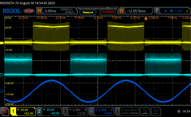 Blue is Peak DC input Current of 100A and AC load of 2.2kW 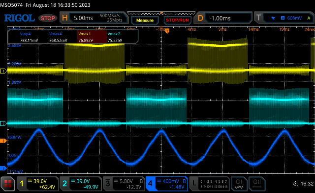 220us HI / LO switching point. 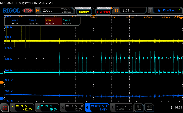 It may not be apparent from these DSO captures but the overall waveform noise and ringing is noticeably improved, especially the duration of leading and trailing ringing under varying load conditions. So I'll keep it at this CAP value for now. I also wanted to touch on the subject of Inrush current again. I had the AC current trip wound down to trip at 300A Peak DC input for initial testing with the new controller, every time I powered an older PC on, the Inverter tripped, it turns out that the older PC power supply draws a peak DC inrush current of 380A. Later when testing at 530A DC input trip setting, I made the mistake of turning a VARIAC back ON immediately after turning it OFF, the VARIAC is a Huge Toriod with a single variable winding. Turning it back on with residual flux in play resulted in a Peak DC input surge current into the Inverter of almost 800A. That's the highest Peak input current I have encountered. This Inverter can handle that if the current trip is set high enough, however I'm not going to allow it to do that any more, so the DC peak current limit will remain at 530A from now on. FYI Some battery charges cause a peak of 260A, a small 13.7v 28A Noiseless Communication SMPS power supply, the size of a thick book, results in a 310A DC peak when powered up. I think about that in the context of having a home running on Inverter AC power, and one of these items is switched on. This surge is also true of larger Laptop power packs, some of those can easily cause a DC input surge of hundreds of amperes on top of an already loaded running Inverter. . It's all too hard. Mike. |
||||
| analog8484 Senior Member Joined: 11/11/2021 Location: United StatesPosts: 108 |
Did the controller over-current protection trip when the MUR420 diode died? After repair with the diodes removed, did you try the same loads again? It's a bit surprising that 2.2kW would cause that much distortion in the AC output waveform. Was the load purely resistive? |
||||
| nickskethisniks Guru Joined: 17/10/2017 Location: BelgiumPosts: 458 |
Since you have a diff probe you can now probe on the most interesting spots. I recently added two to my equipment set too. I think you might find it interesting to probe the voltage over the inductors. It was higher then I expected when examening a diy hf inverter, some inductors have a Nice square WAVE, others do not and are more "peaky". I did not have time to see if there is a correlation between those peak voltages and the source/drain transitions. Also interesting to probe the drain/source of the complete half bridge at the same time. You measure the input current but I think the peak currents can be higher between the output of the h bridge and the inductor/transformer. Be aware of the (rather low) bandwith of most current probes/lems. I was ones probing with one and did not understand the waveforms untill I saw the bandwith... |
||||
| KeepIS Guru Joined: 13/10/2014 Location: AustraliaPosts: 1679 |
I don't know if it current tripped as the DC input Contactor dropped out. It has started those loads 4 to 5 times a day and almost every day since the Inverter was first built, and Yes, it starts them again now. If you look at the heading above the Screen Grab - the Blue trace is the DC input Current sensor, Not the AC output as in the Screen grab above it. It's all too hard. Mike. |
||||
| KeepIS Guru Joined: 13/10/2014 Location: AustraliaPosts: 1679 |
Yes, the Peak DC input current is an order of magnitude higher than the inductor/transformer current, but no matter how you cut it, the Inverter has to sink that peak instantaneous current and share it through the FETs, which is why I have it displayed on a meter on the front of the Inverter. On the diff probe, I'm looking forward to have the time to go over the inverter with this, I've been getting the new controller board built and running with the Inverter power board, in between the Bathroom Renovations, and a dozen overdue chores, so I've not had time to do any serious testing. The probe I purchased is rated at 100MHz Bandwidth and <3.5ns Rise time for what it's worth. However I had to limit how much I could spend, and there are compromises, it appears to be well made in a nice carry case with an assortment of leads. I really want to capture as much visual data as I can for the next time, it should also make building and testing the duplicate backup Inverter I'm building easier to accomplish on the test bench. It's all too hard. Mike. |
||||
| KeepIS Guru Joined: 13/10/2014 Location: AustraliaPosts: 1679 |
FYI: The DSO screen grabs shown a few posts back are all running under 2.2kW load Yes an important point to remember, some sensors that I've tried are very poor. This Current Sensor measurement range is 0 to 750A, I've tested it against a resistive current shunt to 1000A and it's still tracks the resistive shunt for the measured amperes. It is very, very good at isolating external noise from the Sensor Head readings. For what it worth, the quoted DC sensor response time @50A/μS is 10%-90% ≤7μS. I have previous DSO captures going back over two years, so this is a big help with the sensor limitations with respect to linearity and waveforms produced, which is useful as a reference when using the Sensor for ongoing Inverter monitoring and testing. . Edited 2023-08-19 10:46 by KeepIS It's all too hard. Mike. |
||||
| KeepIS Guru Joined: 13/10/2014 Location: AustraliaPosts: 1679 |
For what it's worth, a quick look across each Choke, the waveforms are identical across both chokes so I'll only show one, 2nd zoomed in. 25V per division, apology for incorrect LH scale offset. Edit: It's a bit hard to see every second division for some reason, but there are 8 vertical divisions. 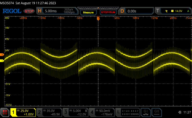 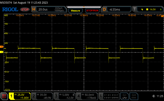 . Edited 2023-08-19 13:12 by KeepIS It's all too hard. Mike. |
||||
| analog8484 Senior Member Joined: 11/11/2021 Location: United StatesPosts: 108 |
 Great! The extra diodes always looked a bit dubious to me. Great! The extra diodes always looked a bit dubious to me.Sorry, my bad. I was starting to wonder if the inverter had degraded in other ways. |
||||
| KeepIS Guru Joined: 13/10/2014 Location: AustraliaPosts: 1679 |
Hi, all good, but on the subject of degrading, it was more a case of what, if anything, had changed in the Inverter since the diode short event and the resulting quick repair of the Power board, and the feeling that something was not quite right, I just couldn't put my finger on it. The spanner in the works was that I had made wiring changes to accommodate the new "untested PCB and the updated controller Circuit" and running with a repaired Power Board. There were some initial component changes needed to the Controller along the way, but all this time the feeling that something was not right. There appeared to be more inverter noise on wiring and extra ringing on PWM waveforms then I remember, it had me wondering if the New DSO was showing things previously hidden, well you get the picture. I've spent time on and off checking everything, even swapping the original Controller in and really not proving anything, and there was a strange random glitch at idle that I could never catch on the glitch monitoring setup. As changes were made, wiring dressed and a ground a plane fitted below the controller, the glitch appeared to disappear, the noise was reduced to the best it has ever been, but still something did not feel right. So last night I had a spare hour and decided to remove the first stage AC filer and replace it with a common mode HF choke with some "RF" Ferrite toriod ring filtering incorporated. As I was removing the filter anyway, I took the opportunity to recheck the Toriod resonance anyway. Now a few days ago I had checked the Toriod Secondary Caps, they measured correctly at 2.3uF, the exact value originally needed to resonate this three stack toriod at 75Hz. The toriod resonance has been checked numerous times over the months of the original build and choke development, but now the toriod was resonating at 119Hz !!!! I remember reading long ago of two reports around a change in Toriod sound and behavior after a high current shock from a FET failure, it seems the toriod core properties had permanently shifted, it was a weird and very random sound from the toriod at idle that had prompted we to have a closer look at the toriod resonance. I found that I had to increase the capacitance from 2.3uF to 5uF to get the toriod resonance down to 75Hz !!! BTW I intend to check the resonance again in a few weeks. Hopefully I'll get some time today to compare the output under load and also see if that strange sound reappears at Idle, the general noise and ringing in the system has also reduced since bringing it back to 75Hz. It's almost like the toriod was going into some momentary runaway self resonance causing a sudden current surge, the surge then knocking the toriod out of the self resonance until the next random cycle repeated? The resonance could have been exasperated by the extra noise and ringing in the system, in turn, caused by the shifted higher 119Hz resonance. A possible vicious circle, or none of the above! Stranger thing  . It's all too hard. Mike. |
||||
| KeepIS Guru Joined: 13/10/2014 Location: AustraliaPosts: 1679 |
I made an RF filter for the Inverter AC output to cover the HF bands, which is where I operate 99% of the time. Interestingly, I decided to rethink the norm of using standard AC filters: Using a HIOKI 3197 Power Quality Analyzer, I found the THD was less with just the RF filter, this consists of two FT140-43 Ferrite toriods with 3 turns of heavy stranded insulated cable on each toriod, a 0.1μF and a 0.001μF across the output and that's it. Again this is less then with a conventional AC filter, I have quite a few I have tested over the past year or two. The noise in the RF gear was virtually eliminated. The THD was around 2% running the Household and workshop load. It was 3.8% with the AC filter, I don't think the Toriod likes seeing it there. I mounted the HF filter in the TOP deck of this inverter where the Inverter AC output connection sits. It's kept a long away form the Toriod and Chokes and Power board wiring. The bottom Deck houses the Toriod and Chokes, I fitted a single heavy wound commercial AC filter Toriod and removed the 1μF cap from the board that was originally across the Toriod output and replaced it with a 0.01. I decided that the Inverter didn't need to see anymore capacitance so close to the Toriod transformer. The rest of the filter was removed from the board. So a very simple setup that had minimum resistive insertions loss, and the results. THD is the same as the Mains AC @ around 2% with the familiar flat top AC waveform that is a product of Household white goods that are mostly Inverter driven, and a lot of SMPS wall plugs devices. The Mains AC waveform has exactly the same flattop as shown in many recent Inverter builds. However the Inverter is down to 1% or LESS on a decent resistive load that helps swamp the other garbage, that is half the Mains 2.2% THD for the same load. The Inverter by itself is around 1.3% unloaded and 0.8% THD with a resistive 1kW or greater load. There is virtually nothing left of the PWM on the AC output, even fully magnified, it's basically a clean sinewave. Very Happy to have got that all cleaned up and finally finished. . Edited 2023-08-20 15:19 by KeepIS It's all too hard. Mike. |
||||
| analog8484 Senior Member Joined: 11/11/2021 Location: United StatesPosts: 108 |
Hmm ... residual magnetism in the core? Didn't think it could make that much of a difference. Does the eg8010 support soft-stop? I believe the nanoverter supports soft-stop which may help demagnetize the core. |
||||
| analog8484 Senior Member Joined: 11/11/2021 Location: United StatesPosts: 108 |
Was the "conventional AC filter" a typical EMI (mostly common mode) filter? If so, that suggests the noise is mostly differential rather than common mode which would make sense. |
||||