
|

|
Forum Index : Electronics : 8 KW Inverter Build
| Author | Message | ||||
Madness Guru Joined: 08/10/2011 Location: AustraliaPosts: 2498 |
Hi Oz, Just the pin 6 part "the pin 6 on the 8010 needs to be heated up, and pushed through the board so it is on the top of the mini board. This becomes the on/off pin, the other two pins on the control board are +5v and gnd, so use a spdt switch for on/off." If I do this is that the same, I don't have room for pin sticking out the top in my case with the big heatsinks. 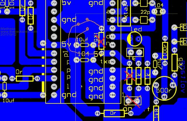 There are only 10 types of people in the world: those who understand binary, and those who don't. |
||||
oztules Guru Joined: 26/07/2007 Location: AustraliaPosts: 1686 |
Thats the wrong pic as you know, this is the one you have in front of you 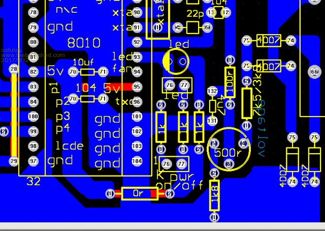 Every thing stays exactly the same except the pin 6 on the mini board goes nowhere ie pin95 does not connect to the bottom board.... it is isolated and goes to the on/off switch which is a double throw single pole.... so you can get rid of pin 6 on the mini, and connect a wire to it to the switch. The on/off pins 76 and 77 go to the switch, such that we connect either +5v or gnd to the pin 6 on the mini board. If you solder directly to the pin 6 ( 95) on the mini. Here is a messy drawing of the changes, ie 95 only goes to the switch, the red tracks are erased by pushing the pin up through the board, or cutting it off and soldering a wire to it instead... ie isolated from everything except the switch pole. 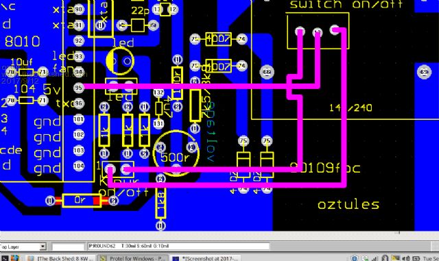 The pink leads go from the 76 and 77 direct to the switch. Clear as mud now? Reason.... as original, pin 6 was turned on permanently, and I used the spare temp switch for on off... as I had issues with pin 6 previously ( I thought)..... but in the end decided to use the pin 6 for on/off, and this tiny change allowed me to use it simply... by pushing the pin 6 ( 95)up , we disconnected the permanently on, and had a pin for the leads to the switch.... simple... But if your o/head room is a problem then you can wire as it is and use temp pins for on/off, or isolate pin6 and solder direct to mini board to switch.... ........oztules Village idiot...or... just another hack out of his depth |
||||
Madness Guru Joined: 08/10/2011 Location: AustraliaPosts: 2498 |
Hi Oz, Thanks for clarifying that, here is how I have implemented the modification. The 3 pin connector fits in nicely against the trim pot, just have to drill a hole in the right spot and cut the track around it and the track to pin 6. 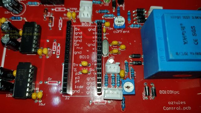 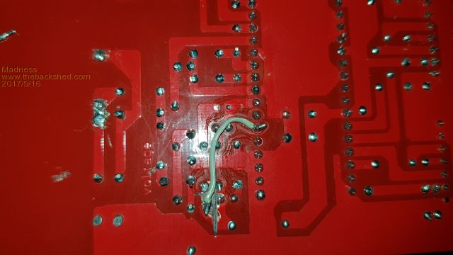 There are only 10 types of people in the world: those who understand binary, and those who don't. |
||||
| Clockmanfr Guru Joined: 23/10/2015 Location: FrancePosts: 429 |
Yes Oztules, very nicely explained from our original discussions. I will take up your PINK colour as a track/cable modification indicator, I like it, as it stands out. Everything is possible, just give me time. 3 HughP's 3.7m Wind T's (14 years). 5kW PV on 3 Trackers, (10 yrs). 21kW PV AC coupled SH GTI's. OzInverter created Grid. 1300ah 48v. |
||||
Madness Guru Joined: 08/10/2011 Location: AustraliaPosts: 2498 |
Just finished assembling one of my new PCB's and the latest version of Oztules control board. 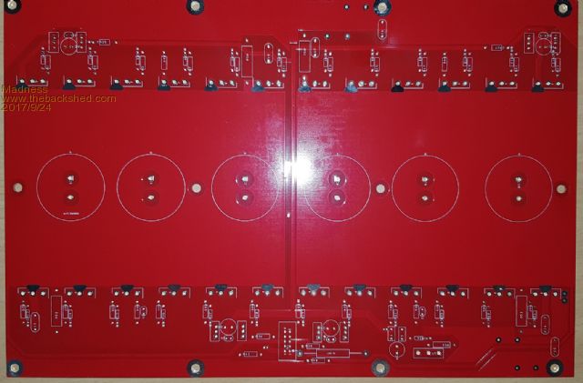 All went together very smoothly with no smoke escaping. 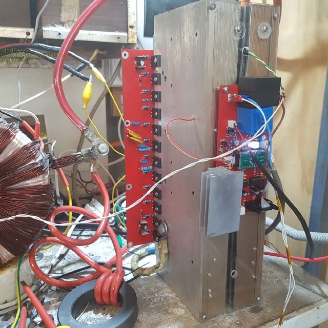 Running here under load as shown on the display. 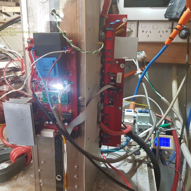 Waveform looks good, very slight little squiggle at zero crossing playing with the choke makes it better. 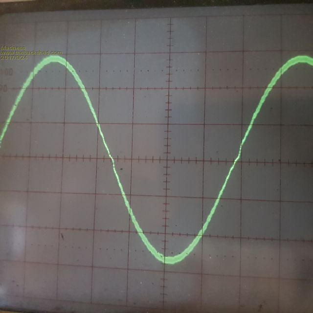 This is the same design as the homemade PCB that I have had running continuously since 13/04/2017. This time I have fitted all 24 MOSFETs and it is running cool as a cucumber, the heatsink is barely above ambient temperature with the load on it for a couple hours and no fans. I have a few of these PCB's spare if anyone is interested. There are only 10 types of people in the world: those who understand binary, and those who don't. |
||||
| Tinker Guru Joined: 07/11/2007 Location: AustraliaPosts: 1904 |
Looking good. A heatsink question, are the main heatsinks ex Aerosharp with the top of the fins cut short? Why such a big heatsink on the control board regulator? do yours get that hot? Mine are fine with tiny heatsinks but then I feed in 12V from a 48V to 12V DC-DC converter, I cant see such a beast on your rig. I'm still experimenting with the Aerosharp chokes re wound & gapped for non saturation. I will report later the outcome but they look useful so save them if you have two of the big ones or two of the smaller ones. Klaus |
||||
Madness Guru Joined: 08/10/2011 Location: AustraliaPosts: 2498 |
Cooler the better is how I see it, the small heatsinks are taken from flat screen TV PCB's I have plenty of them, I am sure bigger is not going to be an issue. Apart from that it is a way to repurpose what some would call junk, taking something that worthless to some people and making useful so it is no longer junk. Power board heatsinks are from the Aero-Sharps cut down on a table saw with an Aluminium blade. This is Oztules idea except I have kept them bigger. They are cut shorter to fit in the case with fans, the height is reduced so the lid will go on and the height of the fins reduced to leave just small gap in between them and more is cut off at the bottom to leave room for the capacitors. Power supply is the same as Oztules 48 to 12 and 5 on the control board and another 48 to 12 on the power board to power the gate drive transistors. Just above the heatsink for the power supply on the power board there is also MOV's to help with lightning protection which I have not seen anyone else bother with. I have plenty of the Aero-Sharp chokes to make use of also when you come up with a good result Klaus. There are only 10 types of people in the world: those who understand binary, and those who don't. |
||||
oztules Guru Joined: 26/07/2007 Location: AustraliaPosts: 1686 |
The commercial manufactured boards now make this childs play to build... sort of like painting by numbers... you throw it together as per board markings, turn it on.... and it just works....makes for easy and repeatable units. Good to see first up success..... it's just getting so ho hum. Well done ....oztules Village idiot...or... just another hack out of his depth |
||||
Madness Guru Joined: 08/10/2011 Location: AustraliaPosts: 2498 |
Thanks Oz, Give me ho hum any day rather fireworks. There are only 10 types of people in the world: those who understand binary, and those who don't. |
||||
Revlac Guru Joined: 31/12/2016 Location: AustraliaPosts: 1026 |
Yep looking nice, first time turn on without sparks. Good one.  Cheers Aaron Cheers Aaron Off The Grid |
||||
| hugocamaras Newbie Joined: 12/04/2019 Location: BrazilPosts: 24 |
Hello! Madness, can you publish the pcb_top, pcb_bottom and Silk pdfs of your power board with Totem? |
||||
| BenandAmber Guru Joined: 16/02/2019 Location: United StatesPosts: 961 |
Madness my goodness look at them heatsinks and clockmanfr that is beyond professional all the other pics on this site you guys really take this to a art form Way Beyond just Electronics some people goes to the car dealership other people go to the ATV dealership I go on here and drool at the pics of the inverters you guys have made be warned i am good parrot but Dumber than a box of rocks |
||||
| BenandAmber Guru Joined: 16/02/2019 Location: United StatesPosts: 961 |
Looks like I'm the only one posting So excited about getting a 8000 Watt Madness board to go with the poida the great Nano control board A friend of mine he's on here his name stairgazer He's a money man a businessman everything's figures to him Me and him was trying to put a figure on what it would cost for a company to have the resources that the back shed has And the numbers we came up with was truly crazy The research and development on these inverters would cost the company over 75 million dollars is what we came up with There's just so much wisdom in one place here and it's just hard to put a price on that So I would like to give a big thank you to everybody that's participated on this form be warned i am good parrot but Dumber than a box of rocks |
||||
| kentfielddude Regular Member Joined: 09/05/2019 Location: United StatesPosts: 89 |
Not sure how you came up with 75 million. I would think that a startup could design a inverter for far less than 75 million assuming they have a qualified team working 8 hours a day soley on the inverter. I agree that the research and development here is valuable and a lot of effort has been put in. |
||||
| ltopower Regular Member Joined: 08/03/2019 Location: United KingdomPosts: 64 |
A startup can go it for $1.... just copy someone elses design as the --------- have done on many many occasions. In todays environment of cut throat competition, cheating nad lying, these forums and posts containing decades of real world experience, honesty and sheer get up and go are a thing to admire. They are one of the real good elements that the internet brings to the world, no borders, no conflict, just a common goal to get on in life and make things easier for all. |
||||
Madness Guru Joined: 08/10/2011 Location: AustraliaPosts: 2498 |
Sorry these files are not going to be published, I have PCB's if you want to buy them at reasonable prices. In fact it would cost you less than getting a small number made yourself. There are only 10 types of people in the world: those who understand binary, and those who don't. |
||||
| BenandAmber Guru Joined: 16/02/2019 Location: United StatesPosts: 961 |
I think we all know on here by now that all your guys is hard work is being copied Research and development And not for an individual user for companies be warned i am good parrot but Dumber than a box of rocks |
||||