
|

|
Forum Index : Electronics : building an Inverter from scratch
| Author | Message | ||||
Madness Guru Joined: 08/10/2011 Location: AustraliaPosts: 2498 |
PCBWay can do 500 x 1100 mm and bigger by request, 1, 2, 3oz and more, 10 layers it seems the sky is the limit. You need to output as Gerber files, Designspark that I use does that no problem, I used Gerbv.exe to view the files, I had to redo a couple spots as they did not turn out as expected when checked in Gerbv. Haven't things changed since the 70's, some for the better, no PC's or the internet back then. Just checked PCB Express and they say this. "You can order gerber files right from our online store! Simply chose Gerber File Conversion and enter your ExpressPCB order number. Gerber File Conversion is $60. If you require multiple Gerber File conversions though out the year you can sign up for our ExpressPCB Membership . With ExpressPCB Membership you get your Gerber File Conversions for free plus discounts on stencils and other online products! Membership is $99/year." There are only 10 types of people in the world: those who understand binary, and those who don't. |
||||
| Tinker Guru Joined: 07/11/2007 Location: AustraliaPosts: 1904 |
Interesting, I just looked up that "Designspark" program and it appears to be free, is that true? RS components seems to be involved with this, I have a customer number with them. I suppose its another big learning curve if I go that way but if its a free program  . .I doubt I would purchase the gerber conversion from Express PCB for just a few boards. Always wondered which PCB program you used from the pictures you posted of your boards but was not aware of Designspark. Klaus |
||||
Madness Guru Joined: 08/10/2011 Location: AustraliaPosts: 2498 |
Design spark is completely free and is not limited in the size of the PCB. The have a mechanical version and others also, I have not looked at them but probably for doing robotics etc. Yes there is a learning curve but there are lots of videos to help. Also you can make a board with a circuit or just drop components on a board and add tracks. There are only 10 types of people in the world: those who understand binary, and those who don't. |
||||
| Warpspeed Guru Joined: 09/08/2007 Location: AustraliaPosts: 4406 |
Klaus, your mention of Bishop Graphics definitely stirs up old memories. I can remember the stick on donuts and pads, and the red and blue tape. The orange film, ferric chloride in the sink, the whole nine yards. Been there, done that.... Then I progressed to getting a free bootleg (de dongled) version of Protel Autotrax. Pretty nice to be able to do it all on a computers screen at home, and get my local board manufacturer to make superb double sided plated through hole boards with silk screen. That was about 35 years ago. At work I always used the professional Protel Schematic and Protel PCB, but at over three thousand dollars a copy, it was always way beyond my reach for home use. The problem was that the Chinese board manufacturers were so cheap it bankrupted all the local board manufacturers. The .PCB files that Autotrax created was originally unique in the world, and for many years none of the Chinese board manufacturers wanted to know about .PCB files, there just was not sufficient demand. So if you had Autotrax, you were left out in the cold, and for a very long time it became more and more difficult (and expensive) to get boards made as the Aussie board manufacturers that used .PCB files all went broke one after another. That is now rapidly changing, there are now several ways to convert .PCB files to Gerber files, but its still not exactly easy to do. Competition is very fierce between the Chinese board manufacturers, and several are now able to use the old Autotrax .PCB files and manufacture superb quality very low cost boards. Fortunately your free Aussie Autotrax is now becoming much more useful now that the Chinese are chasing every bit of business they can get. The American Express PCB free software is really just stolen and rebranded Autotrax under a different name, and the .PCB files that are created by Express PCB are exactly the same as Autotrax .PCB files. For simple low density boards both versions of very similar software are still perfectly adequate for home use and are highly recommended. Cheers, Tony. |
||||
| Tinker Guru Joined: 07/11/2007 Location: AustraliaPosts: 1904 |
Thanks Tony. So you are saying I could send one of my .PCB files to a Chinese manufacturer (do you know of one that can do this) and order good quality boards? That would be brilliant as I would not have to learn another PCB program. Gerber files and all  . .I am not at all familiar with autotrax as I changed jobs, now servicing electronic stuff, before that program arrived. Interesting though that the Express PCB is the same. Klaus |
||||
| Warpspeed Guru Joined: 09/08/2007 Location: AustraliaPosts: 4406 |
I have been using Express PCB free software myself up until very recently, but it was becoming increasingly difficult to find anyone to make my boards using their format. My most recent boards were ordered in Gerber format using very recently purchased software (Proteus Professional level 1 $640), and my latest boards were made by a Chinese company called PCB Way. Talking to the their sales rep, she listed the file formats they can use, and most amazingly one of them included .PCB format. So things are looking up. I can now reorder some older boards if I ever need to. Try contacting PCB Way, their prices are as good as any in the very competitive Chinese market. https://www.pcbway.com/orderonline.aspx They claim three day production, delivery into your hand will be more like about seven to eight days, and the quality is superb. There may well be other Chinese board manufacturers out there that can make boards from .PCB files, but I have not been able to find them. Cheers, Tony. |
||||
Madness Guru Joined: 08/10/2011 Location: AustraliaPosts: 2498 |
A google search found these. PCBWay Everyone will like their price($5 for 10pcs 2 layers board) and short turnaround time. Just 2days delivery. ALLPCB Free expedite PCB prototype, min $5 for 1-2layers with 1-2days lead time, Register to get $5 credit. SeeedStudio PCB Stencil High quality PCB solder paste stencils service with affordable price ZF PCBA Professional in rigid HDI PCB, FPC,rigid-flex PCB manufacture, SMT assembly and components sourcing PCBZOO.com Onlie Quote, PCB prototyping, PCB assembly, laser SMT stencil Service; Fastest: 24 Hours delivery; Provide free online quote software for your website to help you develope and service Customers. PCB Manufacturing Inc We are Leading Printed Circuit Board Manufacturer in China PCBGOGO Best ever PCB and PCBA supplier, quick-turn 24hours and just 10usd for 10pcs of 100mm*100mm board. Best Technology Co, LimitedCeramic PCB,Metal core PCB and Flexible PCB, with prototype, mass production and assembly service. 3PCBIt is playfully brand, stay silly prices,On 3PCB, do not tangle,led the PCB industry for over 11 years, 10 pcs 1-2 layers L≤10cm W≤10cm only $10 PCBcart Professional PCB Manufacturer from China Heros Electronics Professional in HDI PCB, High frequency PCB and MCPCB manufacturing SysPCB China quick turn PCB, PCB Fabricator in Shenzhen China StormCircuit Top Quality,Quick Turn and turnkey service with good price.High tech boards from 2-30 layers,3/3 mil,rigid-flex boards and high frequency (RF) PCB.PCB Assemblyand componets,testing PCBPanel.ORGQuote&Order Online!Here is a house to help PCB designer to get high quantity PCB prototype with low price,by adding your PCB design into other's PCB panel to produce in high technology PCB factory.Meanwhile you can contact other PCB designer to do what you would like. EdadocProvides one-stop PCB capabilities including PCB design, PCB fabrication, PCB assembly and parts sourcing. SOPPCB Technolgy Email: sales@soppcb.com, Founded in 2003,Professional PCB fabrication, PCBA assembly and components sourcing Andwin Circuits Founded in 2003,Professional Aluminum PCB manufacturer,Metal core PCB,FR4 PCB,100% Test Fastline PCB FR4 PCB, Metal Core PCB, Flex PCB, Rigid-Flex PCB exceedingelec NexPCB Founded in 2005, provides Prototype PCB, Professional PCB, PCBA, Turn-key solution. wonderfulpcb PCB board from printed circuit boards(PCB) manufacturer real-pcb FR4 PCB, Metal Core PCB, Flex PCB, Stencil szrcypcb Professional PCB manufacturer supplies products for Sony, Siemens,Samsung,Volkswagen project-pcb PCB fabrication, China PCB manufacturer YuCha Electronic Co.,Ltd Leading PCBA Manufacturing services in china ,Clientele includes giant Companies like Samsung, Sony and so on PCB Robot Specialises in 3 day turnaround PCBs and multi-design jobs at no extra cost. ShenZhen2U.comquality is good for the low price.Recommended. PCB Manufacturing Inc 75% Offer for 2 Layer PCB There are only 10 types of people in the world: those who understand binary, and those who don't. |
||||
| Tinker Guru Joined: 07/11/2007 Location: AustraliaPosts: 1904 |
Wow Gary, did you do anything else today or just research these companies  . .I had no idea there were that many PCB makers. I think I'll try the one Tony mentioned, the price is certainly good. Way cheaper than the blank board would cost at Altronics. Klaus |
||||
Madness Guru Joined: 08/10/2011 Location: AustraliaPosts: 2498 |
It took 10 seconds to find that list. PCBWAY is who I ordered from which is who Oztules recommended to me. I ordered 2 days ago and expect to have the boards mid to late next week, I ended up using DHL for delivery as the order is over 2KG so China post is not an option. There are only 10 types of people in the world: those who understand binary, and those who don't. |
||||
| Warpspeed Guru Joined: 09/08/2007 Location: AustraliaPosts: 4406 |
Heaps of board manufacturers in China, probably dozens. But none of the ones I tried could use the Experess PCB generated files, all wanted Gerbers. I only later discovered quite by accident that PCB Way can do .PCB file format. You won't get boards for fifty cents each in two days, no way is that possible. More like forty dollars for five boards air freighted to Australia in eight days. A very large proportion of the final cost is in the airfreight from China, and the on line quotes are in US dollars. The thirty boards I ordered from PCB Way were 80mm x 50mm arrived in eight days by DHL for $73.00 Australian. I ended up receiving thirty two boards. These will be cell balancing boards for thirty lithium cells. Cheers, Tony. |
||||
Madness Guru Joined: 08/10/2011 Location: AustraliaPosts: 2498 |
My total order is $212 USD delivered for 10 65 X 65, 10 186 X 75 and 5 200 x 300 2OZ boards. If I ordered just 10 boards up to 100 X 100 they are $5 and TURN AROUND TIME is 2 days, delivery via China post is $12 and 25 - 40 days. DHL delivery is $25 and takes 2-3 days. If it is your first order there is also a $5 discount. Go online and check yourself if you don't believe me. Why does it feel like this is a pissing competition????????????? There are only 10 types of people in the world: those who understand binary, and those who don't. |
||||
| Warpspeed Guru Joined: 09/08/2007 Location: AustraliaPosts: 4406 |
Ah yes I see. Production time is 2 days, but delivery can be up to 25 to 40 days on top of that. And the $5 boards can cost $12 to $25 extra to deliver. Not a pissing contest, just reality. Five dollar boards in two days appears to be possible only if you live in China and can pick them up personally from their factory. Cheers, Tony. |
||||
oztules Guru Joined: 26/07/2007 Location: AustraliaPosts: 1686 |
my last order was $14usd and arrived about 6 days from ex factory delivery date.. so $1.40usd/board delivered to remote island. DHL asks for $25, and then another $30usd for remote delivery... so it can get silly if you let it. ........oztules Village idiot...or... just another hack out of his depth |
||||
| Tinker Guru Joined: 07/11/2007 Location: AustraliaPosts: 1904 |
Well, I had some success at last. Finally managed to track down a fault that had me bamboozled for some time (and cost me a few HY4008's  ). ).For some reason on one low side the TIP41/41C pair had gone kaputt. One went open circuit, the other short. The associated iN5819 diode also shorted out. I have no idea why or when it happened but this fault produced some very odd symptoms. Anyway, its working fine now in my test set up. Just 4 Mosfets, one capacitor and a smaller (~2KW) test toroid. That did 1130W easily and the small heatsinks got barely warm. I guess I could push more power through but with the full 24 Mosfet complement the inverter would make close to 7Kw which is plenty for me. I took some pics of the sine wave (sorry about the poor quality, I need a CRO - camera hood) but the waveform is now the best I got yet from this inverter. First with no load, a few tiny wiggles: 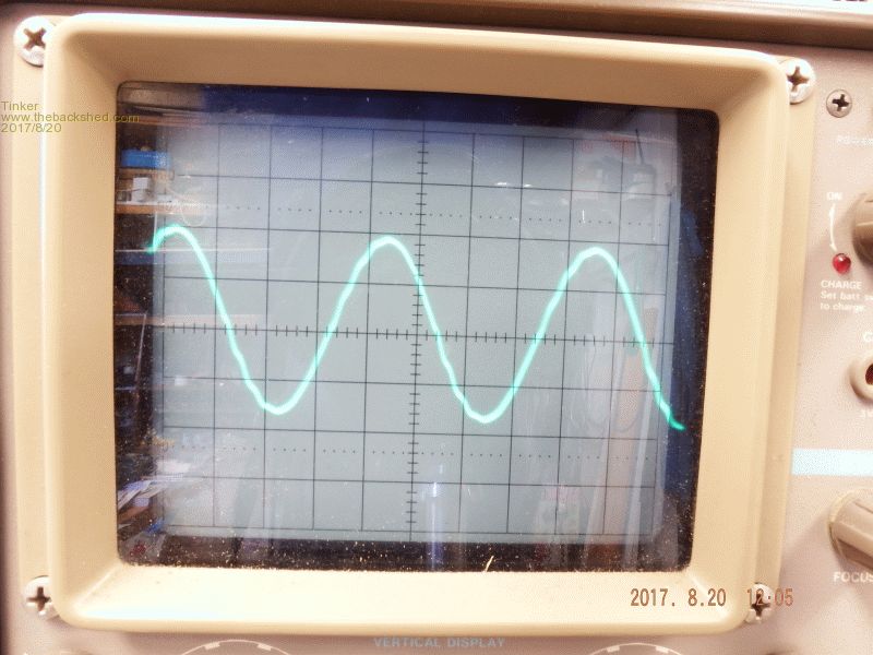 And it gets even better at 1130W: 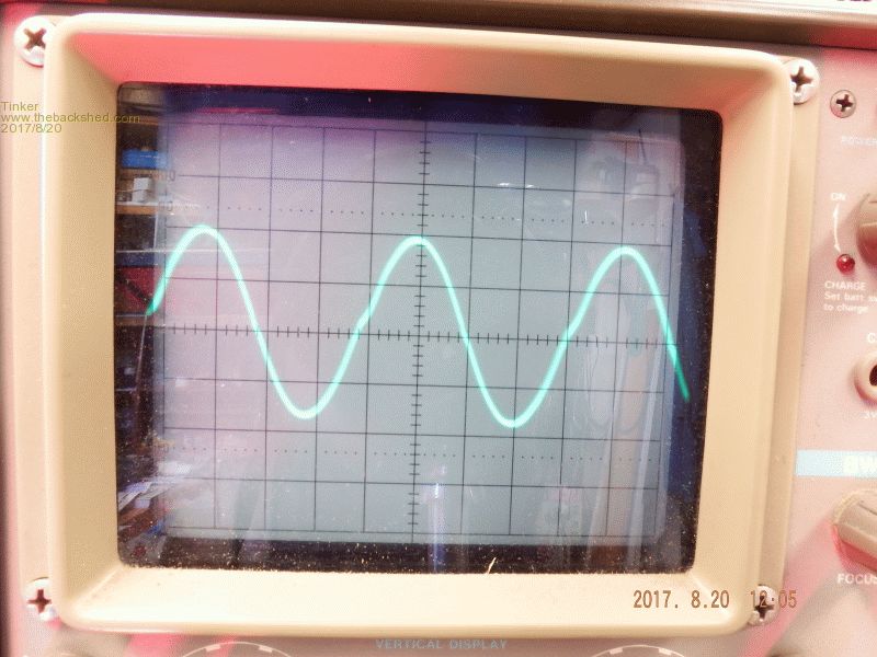 So it appears my large air gap chokes do work. I used one on each side of the primary: 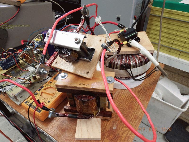 The large one is made of two of the Aerosharp choke cores as discussed earlier in this thread, it measured 173.6uH. The smaller one is the standard ferrite E65 core with 4 turns and 2.5mm gap (4.45uH) The no load idle power was 11.5W with that toroid. I guess this will go up a little with the bigger magnetising current of the double stack toroid. So, now I have to tidy up the PCB artworks and send it to china for a few cheap boards. I also am waiting for yet more Mosfets.... Klaus |
||||
Madness Guru Joined: 08/10/2011 Location: AustraliaPosts: 2498 |
Hi Tinker, When I first built that design I had one pair of transistors that had a short due to a soldering stuff up. However testing each leg individually as I described showed the fault and no MOSFETs were sacrificed. I am running 20 HY4008's and have tested it to 8KW for 30 minutes, the last batch I got measured lower than the spec RDS on. So they run really cool, there is link somewhere on my thread, I got a really good price and fast delivery for 100 of them too. There are only 10 types of people in the world: those who understand binary, and those who don't. |
||||
| Warpspeed Guru Joined: 09/08/2007 Location: AustraliaPosts: 4406 |
Excellent results there Klaus, looking really good ! Those faint wiggles look to me like some high frequency self resonance in the toroidal transformer, probably in the low Khz range. You might like to try lowering that resonance to as close to 75Hz as you can get it with a suitably rated capacitor connected across the secondary. A very rough starting point might be a couple of microfarads. Try tuning just the bare transformer with an audio frequency generator to as close to 75 Hz as you can get. That should further attenuate any faint residual PWM, and may also reduce the tendency for any odd kinks or wiggles, particularly at no load. Cheers, Tony. |
||||
| Tinker Guru Joined: 07/11/2007 Location: AustraliaPosts: 1904 |
The comments from oztules regarding these inverters lacking a low battery voltage shut down had me thinking I should incorporate this idea too. However, subsequent posts about using nanos and whatnots to do this task are too complicated for me. So, for at least my lithium battery bank, which does not suffer high load voltage sag, the very simple circuit below works just fine. The zeners stop conducting below 50V battery and trip the shut down. It has to be manually re-set. 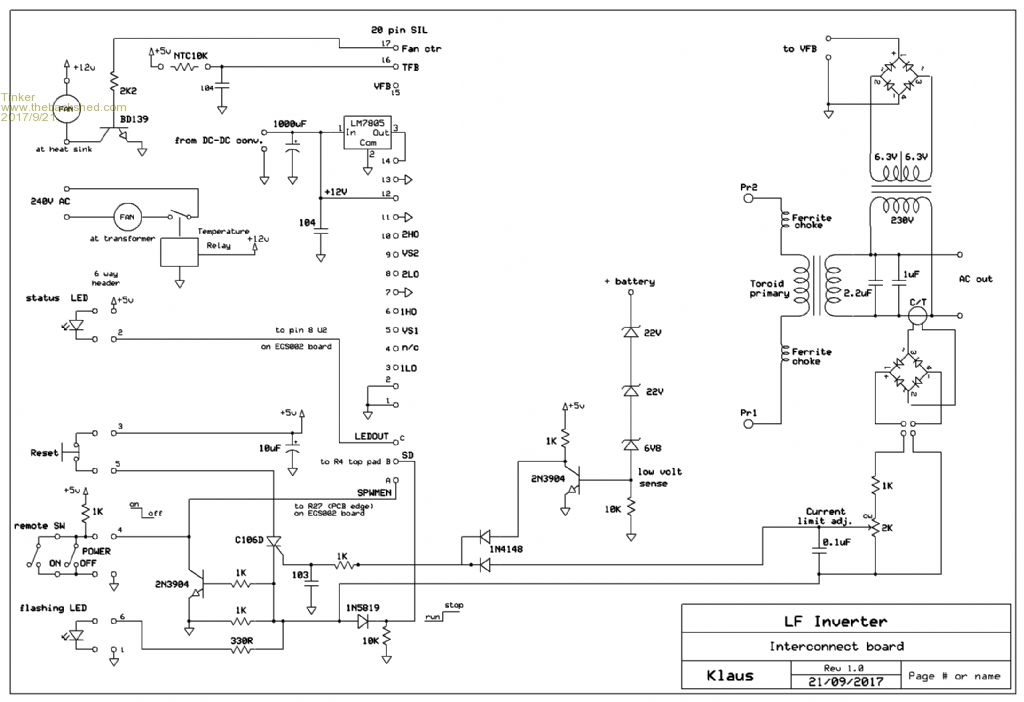 Klaus |
||||
| Tinker Guru Joined: 07/11/2007 Location: AustraliaPosts: 1904 |
Just in case anybody is wondering why no updates in over a month, well, I have been busy... PCB's made in China seems to be all the rage so I joined this idea and was pleasantly surprised with the results. This also gave me an excuse to completely re design my inverter, also successfully. Here is the recipe how I did it: First, take an Aerosharp heat sink and cut it into equal size halves. 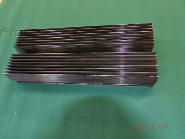 This meant the middle fin was cut out. I required a very neat cut as it becomes the high power connection to the PCB. There also must be a 'shoulder' left to space the PCB underside from the heatsink fin. Next, Trim halves to required length, the long one is 410mm long. Then drill and tap some holes (about 80 actually...), make some plastic brackets and assemble it. 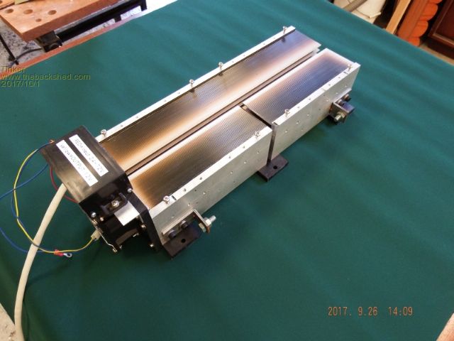 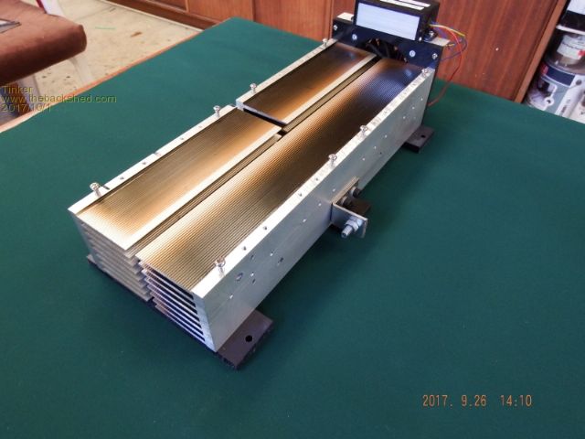 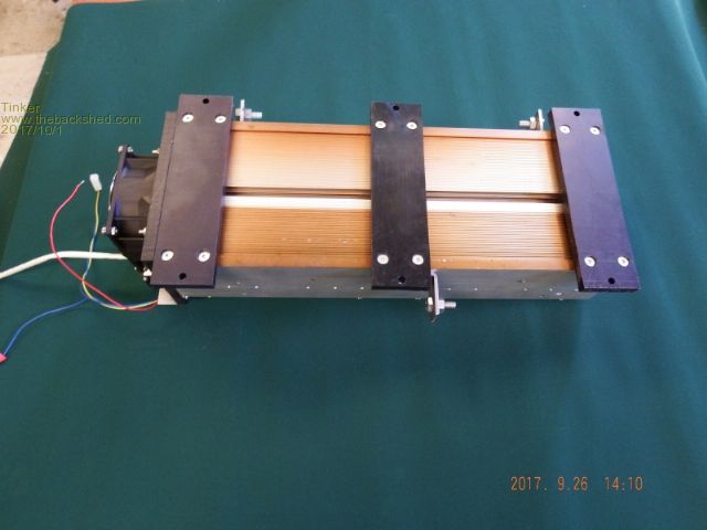 Next, take the two identical main PCB's. Shown below is one of them, left is top side, right is bottom side. 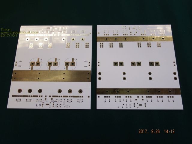 Then incorporate track current capacity increase (thanks warpspeed) and my idea of boosting via current capacity. I did not like the idea of hundreds of tiny vias as on commercial inverter boards. 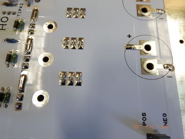 Then start assembling the components. Top & bottom side of one board shown, different size is an optical illusion. 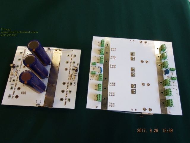 Then, take the three smaller PCB's. All less than 100x100mm. 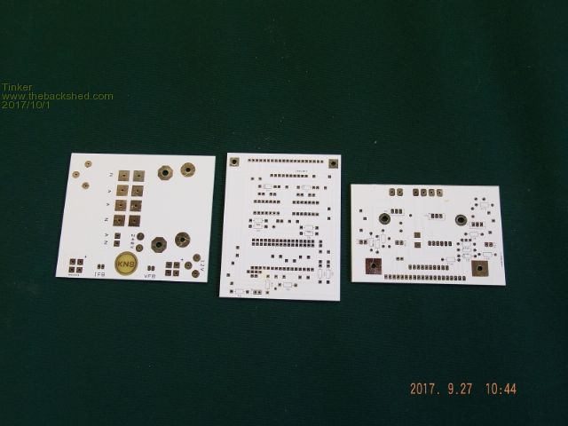 Solder components onto them as well. 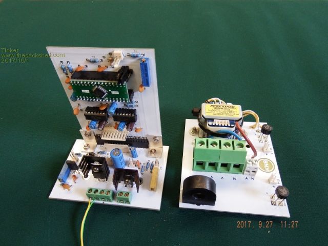 A picture of the main PCB's. The Klapton tape is there because the screws are rather close (~1mm) to the heatsink fin. 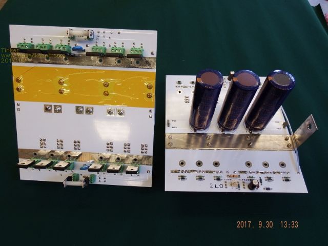 Then wire it all up. 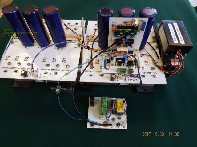 Another view. 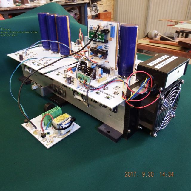 So, does it work then? I hear somebody asking  You bet it does. The magnetising loss of this double stack toroid is 28 Watt. Using the ferrite E65 core (everybody is using) as a benchmark the loss goes up to 35W at idle. This includes a LED power meter. The E core, BTW, required a layer of the adhesive clapton tape on each of the core half mating surfaces. Without that there was a high frequency hash over the top of the sine wave trace. I tried a different way to take pictures of my old CRO screen. 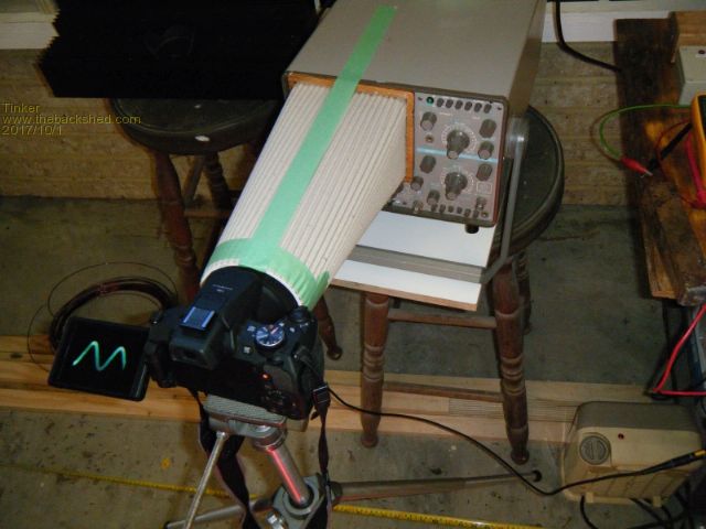 This is the no load wave shape. I could not focus the camera close enough when using the long exposure with this rig. 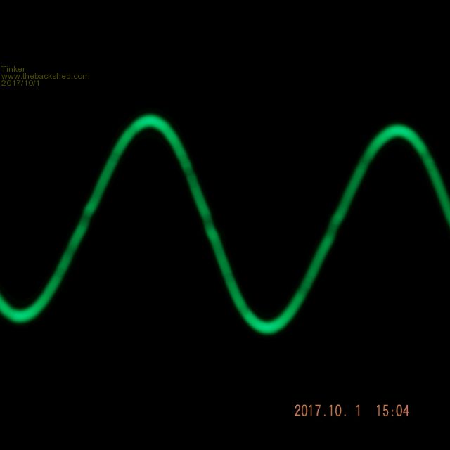 And this is the wave shape at 6200W load. The inverter could go easily a lot higher but with just a 10KWh battery bank I dared not. 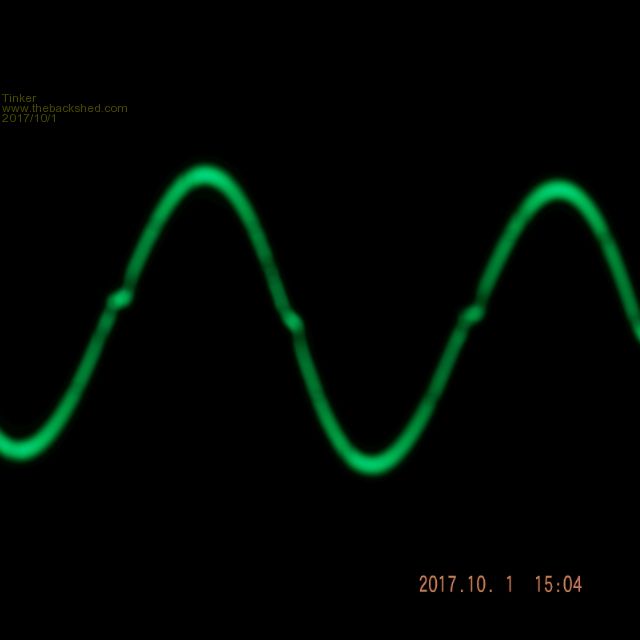 I did wind a 18 turn non saturating choke a while ago. This produced a very nice sine wave up to 2KW but then it started to lean over, quite badly by 3KW. By 'lean' I mean it looked like somebody was pushing from the left at the top peaks of the sine wave. Presently I'm winding another choke, based on the smaller C cores out of the Aerosharp. It has only 9 turns of 52.5mm sq wire (21 x 1.8mm wire in parallel). When its finished I'll do more experimenting, to see if that sine wave improves at the zero crossing with high loads. I will also try different dead times (presently set at 1.5uS). The eagle eyed can see I made this task rather easy  . .Klaus |
||||
Madness Guru Joined: 08/10/2011 Location: AustraliaPosts: 2498 |
Very nice Klaus looks like a very expensive bought one. Once I had it working right I found longer dead time was not good. I look forward to seeing your choke results, what capacitance do you have on the output of the toroid? PS, I found turning the brightness of the CRO down and taking a longer exposure with low background light helps with photos. There are only 10 types of people in the world: those who understand binary, and those who don't. |
||||
| Tinker Guru Joined: 07/11/2007 Location: AustraliaPosts: 1904 |
Thanks Gary, I will try 500ns dead time next. I use a 2.2uF and 1uF cap in parallel, its what I had in mains rating and PCB mounting. I did turn down the brightness until the trace disappeared. The camera is on firework setting, now with the hood and no more reflections on the screen I can try other settings, there are quite a few on this camera. Klaus |
||||