|

|
Forum Index : Microcontroller and PC projects : Beta Testers Wanted
| Author | Message | ||||
| atmega8 Guru Joined: 19/11/2013 Location: GermanyPosts: 722 |
Sorry, i never said that i Vahe a problem with autosave or xmodem. i HAD a Problem with the Editor. But when Setting the lines to 24 everything works fine. |
||||
| Geoffg Guru Joined: 06/06/2011 Location: AustraliaPosts: 3196 |
Unexpected text The bug is new to beta 5. Geoff Geoff Graham - http://geoffg.net |
||||
Grogster Admin Group Joined: 31/12/2012 Location: New ZealandPosts: 9308 |
Geoff Oh, I see - nevermind then.  Smoke makes things work. When the smoke gets out, it stops! |
||||
| Frank N. Furter Guru Joined: 28/05/2012 Location: GermanyPosts: 831 |
Hello, I have the problem that I can't break my running program with CTRL+C if OPTION AUTORUN ON is enabled... Without OPTION AUTORUN ON works all as expected... Frank Print "*** Hello ***"
LED=2 'LED-pin = pin2 SetPin LED, DOUT 'LED-pin as output start: For zaehler=1 To 5 Pin(LED) = 1 Pause 250 Pin(LED) = 0 Pause 100 Next zaehler Pause 500 GoTo start |
||||
| Geoffg Guru Joined: 06/06/2011 Location: AustraliaPosts: 3196 |
Thanks very much Frank. That is an annoying bug indeed, the only way to recover is to re-flash the chip  . .
Thanks also for the easy to understand snippet of code. What happens is that the Micromite starts up with the option key disabled (set to zero) and it is only initialised when you reach the command prompt. Which in your example, never happens. This bug crept its way into beta 5 and I will fix it in the next release. In the meantime the workaround is to insert the following line at the start of your program: OPTION BREAK 3
This will reinstate CTRL-C as the break key. Geoff EDIT: Another "bug" that I have just noticed... the version number in the startup banner says Beta 4 instead of 5. Geoff Graham - http://geoffg.net |
||||
CircuitGizmos Guru Joined: 08/09/2011 Location: United StatesPosts: 1425 |
EDIT: Another "bug" that I have just noticed... the version number in the startup banner says Beta 4 instead of 5. Documentation also says 4. Micromites and Maximites! - Beginning Maximite |
||||
| plasma Guru Joined: 08/04/2012 Location: GermanyPosts: 437 |
connectet a stepper motor to the mighty Micromite. Stepper Video works great , found no bugs  |
||||
bigmik Guru Joined: 20/06/2011 Location: AustraliaPosts: 2914 |
Gday Geoff, My Pic chips finally arrived, so I hope to have a uMite up and running soon.. Just a small edit to the CCT in the manual (page 4) for programming the chip. There is no pin No. (should be 8) shown for the GND connection to the PIC.. Regards, Mick Mick's uMite Stuff can be found >>> HERE (Kindly hosted by Dontronics) <<< |
||||
| WhiteWizzard Guru Joined: 05/04/2013 Location: United KingdomPosts: 2817 |

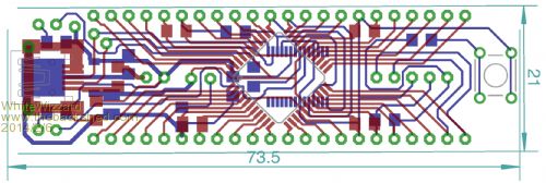
Hi All, Not sure if anyone will be interested in this but with the aim of simplifying Beta Testing I decided to build what is turning out to be a cute little evaluation board for the 44 Pin MicroMite. I will make it openly available as soon as it is finished so watch this space . . . I originally bought various TQFP Break-Out-Boards but none of them gave me 100% of what I needed - so hence the above baby was quickly born! Note that this is work in progress. I only just got the 44 pin PICs late today (50MHz version x 10  ). My plan is to etch the first board tomorrow and hopefully assemble everything by tomorrow night. ). My plan is to etch the first board tomorrow and hopefully assemble everything by tomorrow night.
Headline Features:: - Dedicated yet compact module - can be up and running by simply connecting to PC/Mac (no other BoB's or PSUs required) - Breadboard friendly - Slightly longer than a 40 pin DIP - All 44 pins from the PIC available to user - Built in USB-to-Serial circuit (FT232RL) - Dedicated 3v3 regulator - supplies up to 1A (dependant on USB power source) - Built in ICSP - useful when Geoff sends us his next MasterPiece! - 3 x LED indicators 3v3 Power, Rx, Tx - Power Jumper (save unplugging it all the time when you finish playing/testing) - Reset Switch - Added at the last minute but not yet sure if MCLR enabled to support this So for anyone out there reading this, please give me your thoughts (criticism welcome!  ). By the way, I didn't include any LEDs, Switches, Sensors etc as that is the role of the breadboard!! ). By the way, I didn't include any LEDs, Switches, Sensors etc as that is the role of the breadboard!!
I will update you all tomorrow . . . Regards, Phil For everything Micromite visit micromite.org Direct Email: whitewizzard@micromite.o |
||||
Grogster Admin Group Joined: 31/12/2012 Location: New ZealandPosts: 9308 |
Looks great. 
Let us know how you get on with the etch and prototype build. Smoke makes things work. When the smoke gets out, it stops! |
||||
| viscomjim Guru Joined: 08/01/2014 Location: United StatesPosts: 925 |
Hi Phil, Looks like a great step to take. I am surely interested in acquiring the board. Will it be populated or bare? Thanks Jim |
||||
bigmik Guru Joined: 20/06/2011 Location: AustraliaPosts: 2914 |
Hi Geoff, All, Hooray I have a uMite up and running.. What is the first programme we run? Of course the flashing LED routine.. I copied the code from the Manual and guess what?? SETPIN 15,DOUT errors with invalid pin Setpin 14,dout and Setpin 16,dout both work but not 15.. Regards, Mick PS. I also often get the signon power up message twice.. When I apply power by plugging in the 3v3 volt.. Is this normal? or it could be a bit of bounce as I attach the power wire. Mik Mick's uMite Stuff can be found >>> HERE (Kindly hosted by Dontronics) <<< |
||||
| paceman Guru Joined: 07/10/2011 Location: AustraliaPosts: 1329 |
Hi Geoff, Some issues with the latest documentation. The Octopart & MicroChip Direct links on page 4 put an extra ')' onto the end of the link copied to the browser and stops them working. The Futurlec link on page 5 has a similar but different problem - missing a '(' at the front in the .pdf file. I haven't checked any other links. Greg |
||||
| plasma Guru Joined: 08/04/2012 Location: GermanyPosts: 437 |
@ Bigmike the double Message comes from the power source . |
||||
MicroBlocks Guru Joined: 12/05/2012 Location: ThailandPosts: 2209 |
Adding a R and C to the reset line can help prevent the 'double' start. My favorite way is to use a supervisor chip that holds the reset line active until power is good. They also have a small delay built in. like this one: http://ww1.microchip.com/downloads/en/DeviceDoc/11184d.pdf Microblocks. Build with logic. |
||||
TassyJim Guru Joined: 07/08/2011 Location: AustraliaPosts: 6102 |
Hooray I have a uMite up and running.. SETPIN 15,DOUT errors with invalid pin Setpin 14,dout and Setpin 16,dout both work but not 15.. Mik I can confirm the error. pin 15 was used for wakeup and it has now shifted to pin 16 so I guess the digital got lost in the moving process. The previous beta worked OK Jim VK7JH MMedit MMBasic Help |
||||
Grogster Admin Group Joined: 31/12/2012 Location: New ZealandPosts: 9308 |
My favorite way is to use a supervisor chip that holds the reset line active until power is good. They also have a small delay built in. like this one: http://ww1.microchip.com/downloads/en/DeviceDoc/11184d.pdf Good find, TZA. 
They are only 50c each from Microchip direct in SOIC footprint.(MCP130-315I/SN) Smoke makes things work. When the smoke gets out, it stops! |
||||
| WhiteWizzard Guru Joined: 05/04/2013 Location: United KingdomPosts: 2817 |

Looks like a great step to take. I am surely interested in acquiring the board. Will it be populated or bare? Hi, The simple answer: "which would you prefer?". Once the design is checked and the first home-etch board is successful, I will make the Gerber files immediately available to all of you through a web link. I will also incorporate any worthy hardware mods discussed on this forum (like the RC from the last couple of posts). Passing you the Gerber files will allow you to etch & assemble this Eval Module yourself; but do note there are some very small tracks so some people may find it difficult for a home etch. Alternatively, you could get it etched by someone local. However, if there is sufficient interest I would gladly offer the following: 1> Unpopulated board (reduced postage cost if sent as airmail letter!) 2> Part populated (all SMDs mounted but you still need to solder some parts (i.e. header pins) - for the hobbyist!) 3> Fully assembled and ready to go. I will see if I can make a handful of home-etched PCBs readily available unpopulated on a first come first served basis! 
Now off to begin etching . . . . . Regards, Phil For everything Micromite visit micromite.org Direct Email: whitewizzard@micromite.o |
||||
| Frank N. Furter Guru Joined: 28/05/2012 Location: GermanyPosts: 831 |
Remarks to PWM First I tried this little code but it doesn't work: Option BREAK 3 Print "*** PWM Test***" Do PWM 1,500,50 'PWM channel1 (Pin 26), 500Hz, 50% Dutycycle Loop then I tried this one: Option BREAK 3 Print "*** PWM Test***" HIGH = 1 LOW = 0 PWM1 = 26 'PWM-pin SetPin PWM1, DOUT 'PWM-pin as Output Do Pin(PWM1) = HIGH Pause 0.84 Pin(PWM1) = LOW Pause 0.84 Loop This code works but I must set PAUSE to 0.84ms for a 500Hz frequency?!?! I expected a PAUSE of 1ms!!! But with 1ms I get a frequency of about 440Hz!!! There's a difference if I use a "DO LOOP" or a "START: GOTO START" in the produced frequency. And there is a difference when I write "Pin(PWM1)" or "Pin(26)" and "HIGH" or "1". It makes a difference of about 4-5Hz! The hardware PWM works perfect with this code: Option BREAK 3 Print "*** PWM Test***" PWM 1,500,50 'PWM channel1 (Pin 26), 500Hz, 50% Dutycycle It is necessary to use this command not in a loop! Frank |
||||
MicroBlocks Guru Joined: 12/05/2012 Location: ThailandPosts: 2209 |
Frank, Your observations are correct, and is also the expected behaviour. The 0.84ms to get a 500Hz frequency is because each statement also uses up a little time. When you use the PWM statement in a loop it will change the hardware peripheral each time, this will disturb the peripheral and the output is not steady, even with setting it to the exact same value will cause a disruption. Use DO LOOP or a GOTO will have different execution time resulting in different frequencies on the pin. Exactly the reason why the hardware PWM is so good to use, no more fiddling around with pauses, and the best thing is, your program can do other things and the PWM will be stay steady as a rock. Microblocks. Build with logic. |
||||