|

|
Forum Index : Electronics : 150V 45A MPPT - roll your own
| Author | Message | ||||
| poida Guru Joined: 02/02/2017 Location: AustraliaPosts: 1420 |
Ok, time for an update on the firmware. Recent testing showed that using the softwareSerial library made large changes to how the code runs. I had a 20 kHz interrupt running, doing the pwm changes as needed and maintaining the second, minute and hour counters and flags. I found that my firmware's "minute" was actually 77 seconds when measured with a stopwatch. SoftwareSerial library was disabling the 20 kHz interrupt for periods of time, adding up to about 25% of the time there was no code is executed in the interrupt. Now my code is my code and I will not let some library stuff around with the execution. I hate using other libraries that do things you may not want ever done. This is one reason why I do not support the use of I2C for communicating to the LCD. So I had to write my own code to send 9600 baud serial data out a pin on the Nano. Easy to do and it works well and now the firmware's "60 seconds" = 60 seconds in real time. I had to alter the 20kHz interrupt to be 19,200 Hz, so as to make the serial data rate nearly exactly 9600 Baud when the interrupt frequency is divided by 2. I removed a redundant battery voltage check which also interfered with correct running when Vin is close to Vout (i.e. the max power point is close to max pwm duty width). This situation is found when you want to charge the battery bank with a unregulated DC supply as input and the supply can only give a voltage maybe 2 or 3 volts more than the battery charge voltage required. I was doing this yesterday when we had near zero solar power and lots of rain. I will publish the firmware after I have run it for a few days, controlling the East side roof solar array. If no problems then we can use the code. The code uses 70% of EEPROM storage and 50% of RAM, this is not even close to running out of room. This is quite a satisfactory result for me, I find it amazing what you can fit into the 328P microcontroller. wronger than a phone book full of wrong phone numbers |
||||
| noneyabussiness Guru Joined: 31/07/2017 Location: AustraliaPosts: 513 |
considering there is more processing power in that little chip than what sent man to the moon, its impressive what you can do... fantastic job peter... thank you again from all of us I think it works !! |
||||
| wiseguy Guru Joined: 21/06/2018 Location: AustraliaPosts: 1156 |
Thanks Peter, the boards arrived late last week, money is hopefully already in your account. The E65 cores were delivered today and the bobbin bits will be here by the end of the week, but I do agree that this is a longer term experimental solution and should essentially be ignored for now, I will post the test results later. The performance from your 2 x EE70s looks like a workable repeatable solution and not a lot more expensive that the 3 x EE65s pairs I am hoping to use - what started me down this path was the high-ish cost of 2 x EE70 pairs and postage, but a $20 odd dollar reduction is not really a big deal - unless of course you are in production. Just noting your latest post, if I choose the 40kHz option in the directives will it upset the rtc or baud rate comms? I also assume it will now just be double the 19.2kHz ? Edited 2020-06-22 16:40 by wiseguy If at first you dont succeed, I suggest you avoid sky diving.... Cheers Mike |
||||
| poida Guru Joined: 02/02/2017 Location: AustraliaPosts: 1420 |
Wiseguy: thanks for payment I completely forgot that I was to give a 40kHz pwm option. No problems with baud rate, it will be sorted out in the software. (I just made the change. It's quite special in my view to be able to change pwm freq on the run, via the menu. It works great.) I am rather interested in looking at different pwm frequency/gate drive IC/MOSFET combinations. When there is 5 or 7% loss, knocking just 1 of those 7 percents off is a huge change, 14% improvement in lower heat dissipation. And the 3x EE65 might be better too, it could relate to easier to get enough turns while not increasing copper losses. All the + and - of choices make this project an interesting one to my mind. Edited 2020-06-22 18:23 by poida wronger than a phone book full of wrong phone numbers |
||||
| wiseguy Guru Joined: 21/06/2018 Location: AustraliaPosts: 1156 |
I Just realised I forgot to order some HY5110 or FDH055N15A yet - too many distractions happening here. My Testing will not be valid & mirror your work until I get these parts. Poida, what FETs are you using for the switching and diodes - I am guessing all FDH055N15A for the FETs and MOSDiodes as they all need a 150V rating for your tests ? I am confident that with low on resistance parts like that, 2 will be ample for 45A outputs. I will do further testing at 20 & 40kHz for Gate R & inductance as soon as I get some FETs to play with. If at first you dont succeed, I suggest you avoid sky diving.... Cheers Mike |
||||
| poida Guru Joined: 02/02/2017 Location: AustraliaPosts: 1420 |
Wiseguy: I have 3 boards built. 2 of them use HY5110 for both FET and Diode function. The other board has FDH055N15A as FETs and HY5110 as diodes. The FDH055N15A is rated at 150V and the HY5110 are rated at 100V I tested the HY5110 diode avalanche voltage and it's about 110V from memory The FDH055N15A would be at least 150V and probably more. I've run both board types with a 110V supply. You might think it would be a bad idea with the HY5110 MOSFETs having about 110V rating at the extreme. But the board works fine. I checked for leakage current on the input when no pwm drive is present and it is down in the micro Amps range. I much prefer the FDH055N15A as MOSFETs and I would suggest we use them for diodes too. These parts give the best conversion efficiency and I would say it's about 1 - 2% better than the HY5110 (with 110V input). The less efficiency is due to there being voltage spikes well over 110V present during the ON and OFF switching events, and these will be absorbed by the HY5110 going into avalanche mode and shorting anything above 110V. That's my theory anyway. On testing conversion efficiency, I wish I had a lot more accurate current measurement gear. In fact, I would like something with 0.5% accuracy measuring volts, amps and power. You might not know yet, but running these boards with 57V input, and converting to about 45V at 20A output gives efficiencies of more than 100%. Well, at least that's what my gear, testing and calculations suggest. I made an Over Unity Machine! In other news, everyone in the house is wearing tinfoil hats, to guard against the unknown radiation coming from the OUM. wronger than a phone book full of wrong phone numbers |
||||
| Warpspeed Guru Joined: 09/08/2007 Location: AustraliaPosts: 4406 |
Quite right Peter. Its extremely difficult to make highly accurate power measurements, and even very slight errors can skew the efficiency calculation by an amount that can make nonsense of the results. A completely different approach to all this would be direct temperature measurement. All losses end up as heat (somewhere) resulting in a temperature rise above ambient, and that is often much easier to see or measure. Small changes become much more readily apparent. These days one of those FLIR infrared temperature measurement cameras might be a very useful tool for this. I do not yet own one myself, but they are excellent for finding hot spots and seeing temperature gradients and small temperature differentials. Cheers, Tony. |
||||
| noneyabussiness Guru Joined: 31/07/2017 Location: AustraliaPosts: 513 |
Good Morning Poida, i received boards today.. thank you again.. you packaged them so well I think it works !! |
||||
| poida Guru Joined: 02/02/2017 Location: AustraliaPosts: 1420 |
Oh beaut. I was wondering if they arrived in good condition. You are wanting a parts list? This is an Excel file. 45A parts.xls.zip Recall I suggested a 1K5 resistor on the low side of Voltage IN sensing divider to give enough range to correctly display up to 150V input voltage. I think it's R6. Along with the parts list is the schematic for the power board. Screen Shot 2020-05-30 at 10.28.02 am.zip The brainboard is easy enough to sort out. I suggest you use an IC socket for the Nano. wronger than a phone book full of wrong phone numbers |
||||
| poida Guru Joined: 02/02/2017 Location: AustraliaPosts: 1420 |
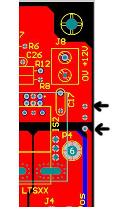
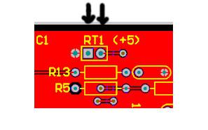
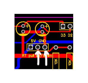
Build notes #2: Previous notes: here Something not discussed here much, if at all, is the important design detail Wiseguy made in the board. This thing is an attempt to isolate the noisy power and switching ground from the sensor's outputs. We need to make a link, connecting 2 holes, to join the sensor ground to the switched power ground. We also need to put a ferrite bead in the link as well. The two pads we need to link:  I would use any ferrite bead I can find, and link it with any copper wire you have easy access to. Next is the thermistors. I would prefer if we all choose to have the thermistors connected to 5V on the board. And on the brainboard we make a link to pull the thermistor output down to ground. on the power board, one of two locations, use the two pads inside the rectangle:  on the brainboard:  wronger than a phone book full of wrong phone numbers |
||||
| noneyabussiness Guru Joined: 31/07/2017 Location: AustraliaPosts: 513 |
thank you for the update.... I think it works !! |
||||
| poida Guru Joined: 02/02/2017 Location: AustraliaPosts: 1420 |
It's been a little while but Mark: do you want me to cut 4mm gap in a pair of the $50 cores, and a 2mm gap in the other pair, then wind enough turns to make about 100uH and test that combo? I don't particularly want to carve into those E cores just on a misunderstanding. I suspect the 2 pairs, one at 4mm gap, one at 2mm gap would need about 15 turns or more to get a reasonable inductance such as 100uH. That inductor would not saturate at 45A and 45V output with 110V input so it is a candidate for the project. wronger than a phone book full of wrong phone numbers |
||||
renewableMark Guru Joined: 09/12/2017 Location: AustraliaPosts: 1678 |
No mate, I meant to use the delta core which has a 4mm centre gap. If you make up another pair with the 1mm gap cores that will be 2mm Then you have a double with one set 4mm and one 2mm. Anyway only do it if you could be stuffed and curious to see the result. I'll be using the iron core choke. Cheers mate. Cheers Caveman Mark Off grid eastern Melb |
||||
| poida Guru Joined: 02/02/2017 Location: AustraliaPosts: 1420 |
ok Mark I have done it. I placed one of the Delta GTI E cores, 4.0mm gap, next to the 2.0mm E 70 core and gave it 12 turns. No more wire available for more turns. 20kHz pwm In 106.7V, 20.2A, 2155W Out 49.8V, 40.7A, 2027W, 94% efficient 13.6A ripple No saturation at 2000W and none even up near 3000W The inductor is 117uH from 12 turns. It's also a good candidate for the project. I can not stress too much how informative it is to test the inductor with the power board and the test program I posted here earlier. It shows how the inductor will perform in this particular situation. No theory needed. We see if it comes up to scratch or not. Edited 2020-06-26 21:07 by poida wronger than a phone book full of wrong phone numbers |
||||
| nickskethisniks Guru Joined: 17/10/2017 Location: BelgiumPosts: 458 |
Hi, I'm trying to calculate some inductors but I have some trouble with interpretation of a certain graph. On page 27 (29) of the pdf, there is a magnetic characteristic. And you have "Percent initial permeability (%µ0). I would expect maximum value of 100%, and minimum 0%. But the Y axis is starting at 100%... https://www.tme.eu/Document/82fc93ef93d05a020041f9203a13131a/MICROMETALS-Tseries.pdf Can someone point me in the right direction? I think the graph shows that the AL value will drop when the flux density is rising, but it shows the opposite? I think I need some rest, it's hot over here... |
||||
| Warpspeed Guru Joined: 09/08/2007 Location: AustraliaPosts: 4406 |
You are looking at the ac magnetization curve. Magnetic characteristics are not linear, shapes vary, but generally its a kind of "S" shaped curve. See some powdered iron shapes on page 25 (page 27 of the pdf) If you start out at zero without any dc or ac magnetisation at all, and measure the permeability right in the middle of the "S" at a very low amplitude, you can come up with a figure for that material. Call that 100% (of whatever that figure is). Now if you energise that core with an ac winding, the ac flux swings equally in either direction around zero. As you increase the amplitude, it swings further in either direction, sweeping back and forth through zero, using up more and more of that "S" shape. That changes the permeability, in fact permeability increases as the ac flux swing amplitude increases. It can rise to being two or three times as much as at zero. If you keep on increasing the amplitude beyond that, it starts to approach saturation at the peaks, and permeability very quickly falls off. This mainly concerns transformers, where idling current rapidly increases as we approach saturation where we are now way above the peak. Reducing flux swing slightly will get us back up towards the peak. This is explained on page 25, (page 27 of the pdf) For choke design you need to scroll back to the previous page 26 (page 28 of the pdf). There you can see the dc magnetizing curve which is a very different shape. The ac magnetising curve uses flux density swing on the X axis. The dc curve uses magneto motive force on the X axis which is a very different thing and can be confusing. The reason for the difference, is that with transformers we are mainly interested in voltage across the windings, volts per turn as the main focus of interest in selecting a core. With chokes we are more interested in the current through the winding, ampere turns, and the effects of that in selecting a core. Current in a transformer, and voltage across a choke are still important factors. Temperature rise and core losses can be significant problems, but we need to start somewhere in an initial design, and then work out the secondary effects. The dc curve is what you should be using for choke design. Initial permeability is the figure quoted on the specification sheet for the particular toroid size and material, and the Al value given is the inductance per turn in Nanohenries which is the 100% Al value. As you increase the MMF (ampere turns) the inductance (Al value) falls, so your choke inductance reduces with increasing current. Some materials like -2 or steel stay pretty much at 100 % Al all the way to the onset of fairly sudden saturation. Other materials such as the common low cost -26 material, offer a much higher initial inductance, but it gradually fades away with increasing current, with a very soft saturation characteristic. Edited 2020-06-27 09:49 by Warpspeed Cheers, Tony. |
||||
| nickskethisniks Guru Joined: 17/10/2017 Location: BelgiumPosts: 458 |
Thank you Warpspeed! |
||||
| SYM-1 Regular Member Joined: 18/10/2019 Location: New ZealandPosts: 45 |
I haven’t got the boards yet but I have a micromite to produce a PWM waveform and a DCOI gate drive circuit good for up to 70V or so. It seems OK at 20khz. I have cobbled together a simple dc to dc converter to test the inductor. I am picking up about 30V from 9 or 10 Lifepo4 batteries (200ah) and dumping the power into 8 of the same batteries. No capacitor. I have about 12 turns of twin speaker wire on the inductor and I can get up to about 25A to flow by gradually decreasing the mark space ratio. After that things go wrong suddenly. I am using 4115 fets rated at about 150V. 104A with 6mOhm on resistance. After the 25A point I go straight to 50A flowing - either my 40A fuse blows or the FET dies. Should I use fewer turns (say half) to reduce the Ampere turns? Or do I need to add 2 more cores? Also when I increase the input voltage (by adding in more cells) I get worse control. Sorry I can’t measure the inductance. Ah ha - I have now read the pdf referenced above and I conclude: I have 2 5.2” type 2 torroid cores. It should be a T520-2 so have an AL of 20 so that gives me 200uH per 100 turns so to get the required 100uH I need 50 turns. But I am just a blind man stumbling around in the dark. Edited 2020-06-27 13:52 by SYM-1 Persistence is the key |
||||
| Warpspeed Guru Joined: 09/08/2007 Location: AustraliaPosts: 4406 |
If you have one T520-2 core the Al is 20 nanohenries for one turn. Inductance is proportional to turns squared. So 20nH x 71 turns x 71 turns = 100,820nH = 100.8uH If you stack two of those T520-2 cores together. 40nH x 50 turns x 50 turns = 100uH H (Orsteads) = 0.4 Pi x 50 turns x 50 amps divided by magnetic path length 33.1 cm. 1.2568 x 2500 ampere turns / 33.1 = 95 Orsteads. (see the curve and formula on page 18) At 95 Orsteads (50 amps and 50 turns) that monster is not even anywhere near saturation. Even at 200 Orsteads (100 amps and 50 turns) it still has 98% of its original inductance 98uH !! Stacking two cores produces twice the inductance, but it will still saturate at the same current as one core would. They both saturate together at the same point. One core is probably more than sufficient, and extra turns above 71, and/or two cores will make a very worthwhile reduction in ripple current. Turns squared is a very powerful factor for increasing the inductance. Edited 2020-06-27 15:07 by Warpspeed Cheers, Tony. |
||||
| SYM-1 Regular Member Joined: 18/10/2019 Location: New ZealandPosts: 45 |
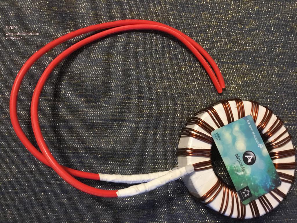
 Thanks for that Tony. That makes things a bit clearer. This is the core with 20 turns on it. I guess I need a few more. It already has 18W I2R losses. With 2 1/2 times as many windings I might need bigger wire (current windings are 3x 2.3mm dia). Grant Persistence is the key |
||||