|

|
Forum Index : Electronics : 6Kw Ozinverter build
| Author | Message | ||||
Madness Guru Joined: 08/10/2011 Location: AustraliaPosts: 2498 |
Neutral is the one that connects to earth in the switchboard, sounds like a smart answer but it is the truth. There are only 10 types of people in the world: those who understand binary, and those who don't. |
||||
| Tinker Guru Joined: 07/11/2007 Location: AustraliaPosts: 1904 |
Mark, if you download the EGS002 manual there is a little capacitor oscilloscope probe shown (easily made) that makes that "fuzzy SPWM signal" clear. This is an easy way to check it. I actually incorporated this cap probe into an old oscilloscope probe to make a more durable version. If you do a lot of testing, like I did  then messing with that flimsy cap/resistor thing clamped to the probe tip gets tiresome. then messing with that flimsy cap/resistor thing clamped to the probe tip gets tiresome.Klaus |
||||
renewableMark Guru Joined: 09/12/2017 Location: AustraliaPosts: 1678 |
Thanks Klaus, do you mean the one on the last page here Cheers Caveman Mark Off grid eastern Melb |
||||
| Warpspeed Guru Joined: 09/08/2007 Location: AustraliaPosts: 4406 |
Yes, thats it. 5K1 (or 4K7) and 100nF. Cheers, Tony. |
||||
renewableMark Guru Joined: 09/12/2017 Location: AustraliaPosts: 1678 |
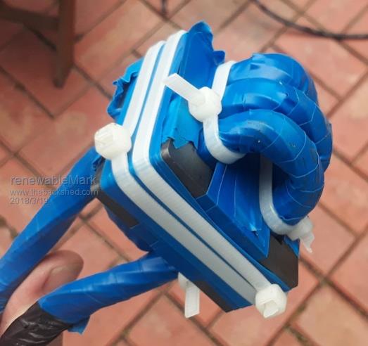
Thanks Tony. BTW I got the heatsinks all drilled and tapped after work today. Got some 70mm2 cable lugs for primary and some cable clamps to link the heavy cable with the choke. I ended up using the recovered wire for the choke, totally amazed I was able to do it, and it actually looks quite neat. Wasn't sure if it would be ok long term as it only has two layers of tape on it, so I just cable tied the two halves together. I put three layers of tape on the mating surfaces so it doesn't hum and vibrate too bad. If it works ok might be an idea to leave it as is and epoxy it a bit.  Cheers Caveman Mark Off grid eastern Melb |
||||
| Tinker Guru Joined: 07/11/2007 Location: AustraliaPosts: 1904 |
Mark, I'm afraid your blue beauty above will squeal horribly under load. OK for testing though. I found sticking a single layer of Klapton tape on each of the mating surfaces (so there are 2 layers of tape when clamped together) quietens it a lot and might even improve the performance. For rigid clamping I fitted one half of the core to 12mm plywood and had a U channel, bent from 2mm alu sheet, on the top side with two 6mm bolts clamping the lot together. No noise from that and you can take it apart later for experimenting purposes. Cable ties won't do for the final clamping job. I'll see if I can dig up a picture somewhere. Klaus |
||||
renewableMark Guru Joined: 09/12/2017 Location: AustraliaPosts: 1678 |
Thanks mate, so no need to add another earth stake where the inverter is fitted? Mine will be in the garage, then connect via the generator/solar changeover switch input socket, that goes 8m to switchboard where the changeover switch is fitted. Re wife, something I learned the hard way was to catch more bees with honey than salt. (In theory) you should get more "funtime" that way. Cheers Caveman Mark Off grid eastern Melb |
||||
renewableMark Guru Joined: 09/12/2017 Location: AustraliaPosts: 1678 |
Thanks Klaus, yeah I can picture that in my head. Reckon I'll use it to test before fitting caps. Edit, found klapton copy locally at jaycar here Alltronics have the real stuff here Hopefully not much difference as alltronics is another 30 min trip. Cheers Caveman Mark Off grid eastern Melb |
||||
Madness Guru Joined: 08/10/2011 Location: AustraliaPosts: 2498 |
Like the Neutral connection to ground definitely no more than one earth. If you have a close lightning strike there will be a potential difference between 2 points causing current to flow if there is a conductor between them. However you should earth the frames of your solar panels, there is no electrical connection to the PV cells. So if you get a hit on the panels hopefully it all goes to ground. There are only 10 types of people in the world: those who understand binary, and those who don't. |
||||
renewableMark Guru Joined: 09/12/2017 Location: AustraliaPosts: 1678 |
Thanks Mad, I did get an earth stake, was kind of hoping to use it as a javelin for pesky door to door salesmen, but alas now it has a useful purpose. In Vic, you don't have to ground the panels if it's ELV (under 120v) but may as well now I have the stake. Cheers BTW they are pretty good value, only $11 Cheers Caveman Mark Off grid eastern Melb |
||||
Madness Guru Joined: 08/10/2011 Location: AustraliaPosts: 2498 |
They may be ELV but with a strike they would become mega HV, the earth is to protect all the stuff down the wires. Being up on the roof they are in a prime location for it. Super glue works to join the Ferrite core together, they can sound like it is possessed otherwise. It is a one-way trip though. There are only 10 types of people in the world: those who understand binary, and those who don't. |
||||
renewableMark Guru Joined: 09/12/2017 Location: AustraliaPosts: 1678 |
Klaus, You said you mounted the ferrite core on plywood with an Al clamp. Did you do that intentionally to isolate it from the metal box? Also I see on various threads some people put a ferrite core on both sides of the primary cable. Is that just to overcome any unwanted ripples in the wave? With the core itself does it vibrate the wire in it? If so I'll have to get some properly insulated wire for it. Cheers Caveman Mark Off grid eastern Melb |
||||
| Tinker Guru Joined: 07/11/2007 Location: AustraliaPosts: 1904 |
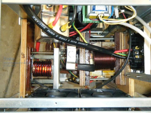
A picture says a thousand words so I took one of my latest inverter (not quite finished yet) to show how I mounted my two chokes.  The ferrite one is on the left, it is in the high side of the primary. The choke on the right is a non saturating type, made from 2 cores of the original 3KW Aerosharp chokes. The reason for that extra choke was discussed at length among these electronics forum posts, I suggest you read up on that topic, well worth while I think. If I were you I would just get the inverter going with the choke you have now. Then, when all is well you can start to improve the sine wave shape with the extra choke. You would do well to epoxy encapsulate the winding as, yes, the wires will try to vibrate and that is no good. The ferrite core itself vibrates at the mating surfaces, that is why it requires secure clamping or super gluing - I would do the latter *only* after you completely finished experimenting. As you see on the pic, I used rectangular wire in parallel for the little choke, it is also epoxied. The big choke has many (I'll have to check how many) parallel wires of 1.8mm diameter to get the cross section area required. It was wound on a special former, 3 in hand at a time and as many layers of that as would fit the cores. If you want to go down that road perhaps better after you get that monster going first. Klaus |
||||
renewableMark Guru Joined: 09/12/2017 Location: AustraliaPosts: 1678 |
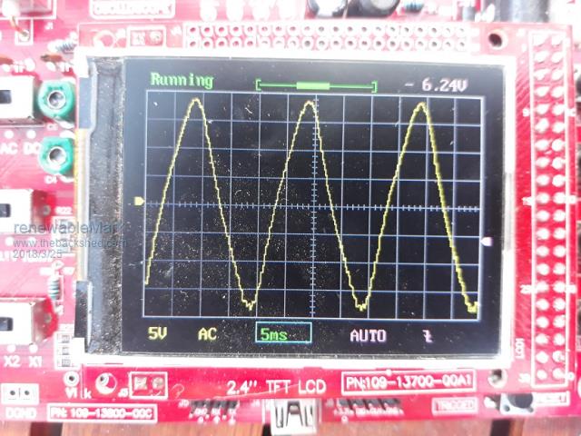
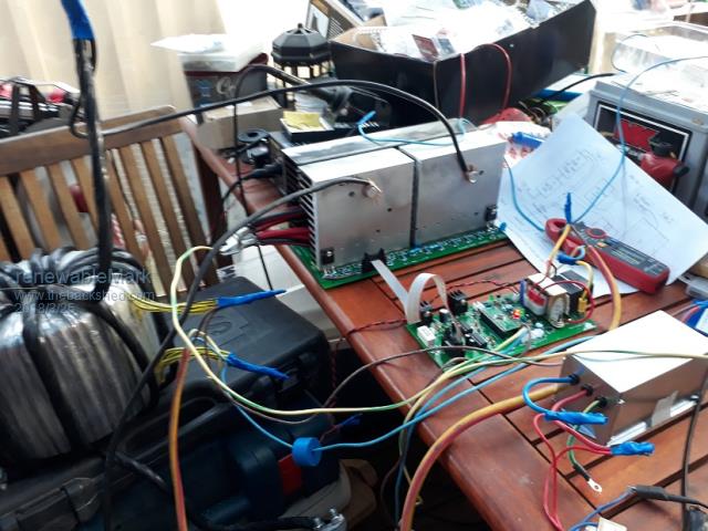
Well I got the bastard to run and give me a nice wave! ripper! But I only have 4 fets fitted and no caps. For some reason it's drawing 2.6Amps. I just spoke to Mad, he seems to think it might be because there are no caps on yet for it pulling that much. Has anyone had a similar result. I swapped the choke to the other heatsink, it had zero change.   Cheers Caveman Mark Off grid eastern Melb |
||||
| johnmc Senior Member Joined: 21/01/2011 Location: AustraliaPosts: 282 |
Well done Mark cheers john johnmc |
||||
| noneyabussiness Guru Joined: 31/07/2017 Location: AustraliaPosts: 513 |
Try a smaller value cap... maybe around the 1000uf, may save your Mosfets if something up, but should improve current draw if it is that.. I think it works !! |
||||
renewableMark Guru Joined: 09/12/2017 Location: AustraliaPosts: 1678 |
Thanks mate, been a long time in the making. Bit curious about the 2.6A though. When I tested the toroid by itself it drew stuff all. Cheers Caveman Mark Off grid eastern Melb |
||||
| noneyabussiness Guru Joined: 31/07/2017 Location: AustraliaPosts: 513 |
Also remember your driving the low voltage side, so current will be higher.. 240v 30ma is " the same " as 24v 300ma.. if that makes sense. .although 70 odd watts idle seems a bit high but not unheard of.. I think it works !! |
||||
| Warpspeed Guru Joined: 09/08/2007 Location: AustraliaPosts: 4406 |
The extra current is almost certainly caused by high frequency switching losses being added to the toroid no load losses. Cured by fitting a bigger, better, or different choke in series with the primary. Fitting 1,000uF at this stage will probably make the idling current slightly higher. Cheers, Tony. |
||||
renewableMark Guru Joined: 09/12/2017 Location: AustraliaPosts: 1678 |
Well I added 2x 560uf 450V caps that came off the aerosharp and it dropped to 0.89A So that's around 43watts, not bad. I just sat them there and twisted the tabs a bit to keep a tight fit. Lets see how it goes with all the components fitted, hopefully, no magic smoke! Sadly I don't have a big battery yet, so I can't test it properly. So next step..... fit the fets in groups of 4 and test the wave each time. Ripper, looks like it's going well, too well. I worry when something complicated goes this smoothly. Cheers Caveman Mark Off grid eastern Melb |
||||