
|

|
Forum Index : Electronics : building an Inverter from scratch
| Author | Message | ||||
| Warpspeed Guru Joined: 09/08/2007 Location: AustraliaPosts: 4406 |
If we know the voltage, on time, and current reached, that will tell us the inductance. L microhenries = Voltage x On time in micoseconds divided by peak current in amps. Then we can work out the theoretical inductance of only one turn. Then we can calculate the inductance of eighteen prospective turns pretty accurately. Your waveforms look very nice indeed. That saturation is pretty sudden and violent! If your inverter ever did something like that up near full load, your mosfets might not be be at all happy. Cheers, Tony. |
||||
| Tinker Guru Joined: 07/11/2007 Location: AustraliaPosts: 1904 |
More saturation testing: The parameters are a little different from above. Test frequency : 101Hz Air gap ; 2 x 2mm Test coil : 125 turns of 5 mm sq Voltage at capacitors (just before saturation): 43.9V Peak current at that voltage : 20A Current drawn from capacitors : 0.579A A picture taken with my other camera: 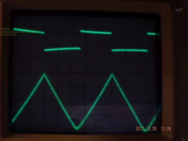 The hall sensor is bidirectional (did not say so in the specs when I ordered it) and its zero current output is 5V DC. Each Amp passing through increases (or decreases this by 40mV. The current trace is 200mV/div, set to AC to allow for the 5V offset. According to Warpspeed's formula that should give an inductance of one milli Henry. Is that right? my maths are a bit rusty these days. The slight increase in the air gap seems to have made no difference to the max Amps before saturation. Perhaps this was because I doubled the test frequency? Now the final coil has been begun, the first layer is on and the ends being epoxied to keep them firmly in place. 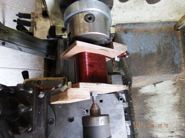 Klaus |
||||
| Warpspeed Guru Joined: 09/08/2007 Location: AustraliaPosts: 4406 |
L = E x Ton/I L mH = 43.9 x 4.95mS / 20A 10.86mH That sounds about right. One of those cores with 84 turns gives around 2.8mH. You now have two cores, and more turns, but a slightly larger gap (2mm vs 1.6mm). One turn would be 10,860uH divided by 125, again divided by 125 = 0.695uH Eighteen turns will be 0.695uH x 18 x 18 = 225uH Saturation is 20 Amps x 125 = 2500 ampere turns. Final choke good for 2500/18 = 139 amps peak. (about 98 amps rms in the primary). Your toroid turns ratio will bring that down to secondary rms amps. Sounds like a goer Klaus !! Cheers, Tony. |
||||
| Warpspeed Guru Joined: 09/08/2007 Location: AustraliaPosts: 4406 |
I now use a similar setup on my own lathe for winding things. Its very easy to get distracted and mis count turns, so I fitted a Chinese turns counter to my lathe. Its very important that every layer has exactly 18 turns. Haha, I bought one of these for $20.00, they are now only $14. http://www.ebay.com.au/itm/Metal-Housing-5-Digit-Resettable-Stroke-Pull-Counter-75-I-/302265895335?hash=item46607389a7 I expected at that price it would be matchbox size, made of plastic and with a 3mm shaft. But no !! it is huge. As big as your fist with a 6mm shaft. And very solidly built from metal. Cheers, Tony. |
||||
| Tinker Guru Joined: 07/11/2007 Location: AustraliaPosts: 1904 |
Thanks for checking my calculations Tony, much appreciated. 98 amps equals 5292 watts drawn from the battery bank, that kind of current should not happen in my set up. In any case, I will set the over current shut down to a 5KW load. I do use a turns counter, its an old fashioned 3 digit one (no shaft) with a lever to advance and a knob to reset. You might have seen them attached to clip boards people used in the past to count things passing by. But, with winding on 2 in hand simultaneously, and exactly one one full layer (68mm wide) its easy to see when 18 turns are on. The counter is just to double check. After having done another layer today this is going to be a tedious job as I have to lock the ends firmly in place each layer. Using fast setting epoxy that does not set really fast in my cold shed will keep me at this for a few days to do 10 layers. Klaus |
||||
| Warpspeed Guru Joined: 09/08/2007 Location: AustraliaPosts: 4406 |
[quote]98 amps equals 5292 watts drawn from the battery bank, that kind of current should not happen in my set up. [/quote] That is the general idea, the choke should always be run well below saturation with a very generous safety margin. you have plenty of inductance, so there is always the option of opening up the gap very slightly, but it sounds excellent just as it is. Using many layers of epoxy is certainly a very slow process, but it makes for a really good final job. Cheers, Tony. |
||||
| Tinker Guru Joined: 07/11/2007 Location: AustraliaPosts: 1904 |
So I finished winding that power choke now. Not the easiest of jobs doing it this way but definitely the only way to get a fair number of turns at a reasonable cross section onto these cores. While there was room for ten layers of 1.8mm wire, in the real world I only managed to fit 9 layers. Still not bad, 45mm sq total @ 18 turns. Now the tedious job of stripping the enamel of the 36 wire ends has begun, so I can solder on a connecting lug. Meanwhile, since I have that marvelous coil saturation tester now, I decided to wind a test coil to fit the E65 ferrite core everybody uses as a choke in the primary side. This, with a 1.7mm air gap, saturated at 660A/t. The same rapid current increase once saturation was reached as with the big choke mentioned before and a similar, very linear, current ramp at 100Hz test frequency. The linearity of the ramp diminished very slightly with a 60Hz test freq., the lowest my tester will adjust to. With my 4 turn high current coil for that E core I would get saturation at a peak current of 165A. The plan is to connect this choke in the second leg of the primary as an insurance. So I tested it with a bigger air gap as well. Using a 2.5mm air gap it saturates at 960A/t, giving my 4 turn power coil a 240A peak margin. I'll try that soon, also to to see what happens to the idle current with the air gap chokes fitted. The latest version (Mk 8 or 9?  ) of my inverter is finished now, ready for testing. ) of my inverter is finished now, ready for testing. Klaus |
||||
| Tinker Guru Joined: 07/11/2007 Location: AustraliaPosts: 1904 |
Its been a while since I tinkered with this inverter, other things to catch up with... Anyway, I'm stumped now, can't get that thing going at all now    The new board is based on a circuit that Solar Mike posted, back on the 29th of March. This worked for Madness but for some reason not for me as yet. I'm sure I done something silly but no matter how hard I look at it the penny will not drop  . .Any ideas are very much appreciated. I'll attach the schematics below. Symptoms: no magic smoke and no sine wave at all at the transformer. Just 4 Mosfets connected for now. These switch fine if tested individually, switching a car spotlight. All 4 outputs of the EG 1810 show a square wave. Ditto on the IR2110 Hi & Lo outputs. Drive signal still present at the mosfet gates. Perhaps the mosfets turn on in the wrong sequence but I would think that surely demands magic smoke?? Since I am not fully sure what kind of drive signal wave form I should see at the Mosfet gates perhaps I could be enlightened here? In particular, referring to my "Driver mother board" schematic, from the top Mosfet down to the bottom one. And the sequence they turn on? I thought its 2HO + 1LO then 1HO + 2LO and repeat.... But I could be wrong. Does anybody know a site that explains a full bridge mosfet inverter well in a simple way with perhaps wave form pictures (not bags of mathematical mumbo jumbo)? The signal generating board: 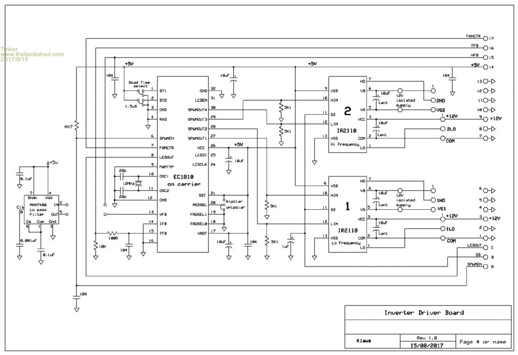 And the power board. Please ignore the left half of the schematic for this post. 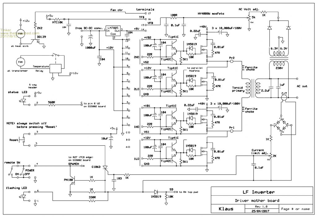 Thanks, Klaus Klaus |
||||
| Warpspeed Guru Joined: 09/08/2007 Location: AustraliaPosts: 4406 |
If you disconnect the transformer, you should see a very clean 50 Hz square wave on Pr1. No high frequency PWM, just alternately on and off, ground and battery at 50Hz. Pr2 will switch at 20 Khz and will look like a mess if viewed directly. On page six of the EGS002 datasheet there is a low pass filter test circuit that consists of a series resistor of 5K1 and a 100nF capacitor to ground. These values are not at all critical, 4K7 will work fine. If you connect the 5K1 to Pr2 output, and connect your CRO probe across the 100nF, you should see some funny looking half sinusoids that look exactly like the waveforms shown on page six. http://www.egmicro.com/download/EGS002_manual_en.pdf The same identical waveforms but at lower amplitude should also be on the four mosfet gates and gate drivers. Cheers, Tony. |
||||
Madness Guru Joined: 08/10/2011 Location: AustraliaPosts: 2498 |
Hi Tinker, I know this is not comforting for you as I have been your shoes also but my inverter has been running nonstop since early April. I did turn it off once to disconnect my old Trace inverters from the switchboard, that was only done for my safety. It has been working flawlessly, still using the original Oztules (big thank you to John for making this possible) control board, it is the version before the ones with the SCR. I am using the choke you sent me, the waveform still has a small blip but that does not seem to matter. My circuit is the same as posted by Solar Mikes (thank you again Mike) except I included the Snubbers as you have done. What I can't see on your circuit is where VB1 and VB2 are connected to, I have a diode (UF4007 on Mikes circuit) between each one of those points and the 12V power supply. Without the diode, you will not get the high side MOSFET to turn on. I see you show the Isolated 12V supply at the IR2110's, this is the only difference I can see between your circuit and mine. I have had EG8010 chips that will not start up reliably with capacitors on the power PCB unless I powered it on with the 300A breaker I use for the inverter. Powering up the control board on its own was no problem, Oztules mentioned he had some issues like that also trying to power up the board via a resistor. What I had done for testing is to connect 12V on the control board to the VFB circuit, this keeps the control board running with no power board connected. then using the low side output you can connect it to each gate drive to individually confirm they are working. The high side signals from the control board are just very slight squiggle on the CRO until the power board is operating. I am tidying up my PCB layout a little to get some blank PCB's manufactured in China. This is mainly to have a couple spares on hand as shortly I will be moving and will be relying on the Inverter completely. There are only 10 types of people in the world: those who understand binary, and those who don't. |
||||
| Tinker Guru Joined: 07/11/2007 Location: AustraliaPosts: 1904 |
Thanks Tony & Gary I tried the scope between PR1 & PR2 and got nothing. Will try just PR1 tomorrow. Also the test circuit in the PDF manual you mentioned. I do have a suspicion the EG1810 might be funny. I have another one on a carrier board but that has the same symptoms. So I'll have to make another yet - tiring work soldering these tiny SMD's for my old eyes. Yes, I do use two separate isolated 12V supply bricks to power the high side. That way my chicken squaks before the egg hatches  , don't like that diode idea . , don't like that diode idea .And I also use your method of feeding 12V to the VFB circuit, saves having 240V on the board while I shuffle CRO probes about it. Thanks for the tip about using the low side output to test the gate drives individually. I'll keep you informed but don't hold your breath  . . Klaus |
||||
Madness Guru Joined: 08/10/2011 Location: AustraliaPosts: 2498 |
Hi Klaus, I have seen people using a stand alone hot plate like a kitchen stove to solder SMDs. Just put flux and solder paste on and gradually heat it up till the solder paste melts. If you just power up the 8010 board on its own will soon confirm if it is a dodgy power up problem. From memory when it is in a coma there are is no blinking LED. Good luck hatching those eggs, watching the startup with the CRO connected the 8010 puts out square wave initially on both sides of the bridge, maybe that has something to do with preventing premature "squaks". There are only 10 types of people in the world: those who understand binary, and those who don't. |
||||
| Solar Mike Guru Joined: 08/02/2015 Location: New ZealandPosts: 1138 |
Hi Tinker Are you getting 0 to 12v peak drive pulses across each of the 5.1k resistors connected to the Tip42/2 common emitters, if so, and the mosfets have a 48v supply, they should be switching the transformer primary. To test just the bridge components, if you disconnect the toroid primary and place a 100 ohm resistor or a 48 volt lamp across bridge Pr1/2, then unplug your IR2110 driver chips, you can test each mosfet pair and get the lamp to light up by shorting the drive to the 22 ohm resistors of the tip 41/2 to their respective 12 volt supply or 0volts with a 100 ohm resistor, do this on both 1LO/2H0 then 2L0/1H0, lamp should light in each case testing the bridge components. Noticed your cct has 10uf tant caps on the IR2110, perhaps not a good idea, they fail randomly by partial shorting and are not suited to discharge applications, use a 105c electrolytic here. If that works and the IR2110 are getting drive from the 8010 then it sort of leaves the 8010, Cheers Mike |
||||
| Tinker Guru Joined: 07/11/2007 Location: AustraliaPosts: 1904 |
Thanks for the tips. Solar Mike, I will replace the tantalums, I have suitable electrolytic caps. It appears the EG1810 had lost its high side output. It put out an identical signal than that at the low side. All the other components tested out fine. Since applying an identical signal to PR1 and PR2 would not do anything - as I discovered, the faulty chip was to blame. After you kindly mentioned what signal to look for the diagnosis was easy enough. I have made up a new carrier with the SMD EG1810 on now and possibly make some more as this task is a bit delicate for old eyes. Testing done today was with with a low voltage on the bus and no caps, no transformer and only 4 Mosfets. Signals at PR1 and PR2 were what they should be. Tomorrow I will see what it does with the transformer & choke connected. Below are a couple of pics of my power board for your interest. Its different from other inverter builds. 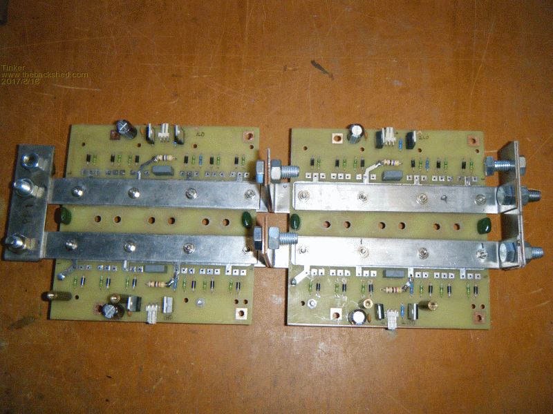 Top side is shown above. Two identical 150mm x 150mm boards, one for the low side and one for the high side. The busbars on the underside, exiting between the boards, are the positive and negative rail. No capacitors are fitted yet, they are the screw on type and fit in the center between the power rails. PR1, located on the left and PR2 on the right outside of the boards connect to the primary via chokes. The 4 screws fixing the busbars to the board have insulator bushes on the underside to stop shorting out the power & primary rails. 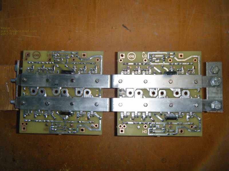 This shows the underside where the Mosfets live. Only 4 of the 24 are fitted for testing. The source & drain legs clamp under the busbars, only the gate leg is soldered on. Klaus |
||||
| Warpspeed Guru Joined: 09/08/2007 Location: AustraliaPosts: 4406 |
That is super neat Klaus, very impressive workmanship. Cheers, Tony. |
||||
| Solar Mike Guru Joined: 08/02/2015 Location: New ZealandPosts: 1138 |
Excellent Klaus, modular construction and ease of servicing in your design layout, that is the way to go. Cheers Mike |
||||
| Tinker Guru Joined: 07/11/2007 Location: AustraliaPosts: 1904 |
Thanks guys, but it comes at a price  . The holes have to be super accurate for everything to line up. Its also my first attempt to make a double sided PCB, another challenge for the home tinkerer. . The holes have to be super accurate for everything to line up. Its also my first attempt to make a double sided PCB, another challenge for the home tinkerer.Klaus |
||||
Madness Guru Joined: 08/10/2011 Location: AustraliaPosts: 2498 |
Nice engineering Klause, I found it quite easy to clean up solder between the legs of the 8010 very easy with solder wick. Having SMD flux on it helps a lot with the soldering too, just the slightest bit of solder on your iron flows right to where it is needed. Less solder is definitely better than more on your iron. There are only 10 types of people in the world: those who understand binary, and those who don't. |
||||
Madness Guru Joined: 08/10/2011 Location: AustraliaPosts: 2498 |
After getting PCB making working right for me, I have decided to follow Oztules and order boards made in China. I can't buy the materials for what it costs and end up with solder mask and silk screen which I could do with a lot more effort but best of all they are plate through which I can not do. They will assemble boards too, getting the EG8010 on a board may be a viable option. There are only 10 types of people in the world: those who understand binary, and those who don't. |
||||
| Tinker Guru Joined: 07/11/2007 Location: AustraliaPosts: 1904 |
Yes, if I needed more boards that would be the way. But I'm forever 'improving' my design, there's a shoe box full of superseded boards in my shed  . I suppose that harks back to the seventies when I did PCB layout commercially, using the old Bishop tapes. I wish I had my simple free PCB layout program back then, so much easier to modify a board on the screen than by ripping off narrow black tapes of a mylar sheet. . I suppose that harks back to the seventies when I did PCB layout commercially, using the old Bishop tapes. I wish I had my simple free PCB layout program back then, so much easier to modify a board on the screen than by ripping off narrow black tapes of a mylar sheet.Just out of interest, what kind of info do the Chinese board makers require? I dare say its a bit more than the express PCB files I use, I have no knowledge of gerber files or whatever oztules used. Also, is there a limited size or can they do 150 x 150 mm? Klaus |
||||