
|

|
Forum Index : Windmills : visual effect of capacitors
| Author | Message | ||||
| Gizmo Admin Group Joined: 05/06/2004 Location: AustraliaPosts: 5078 |
I see there was a post by user spacejunk on Fieldlines some time ago about using a voltage doubler on 3 phase, different circuit. 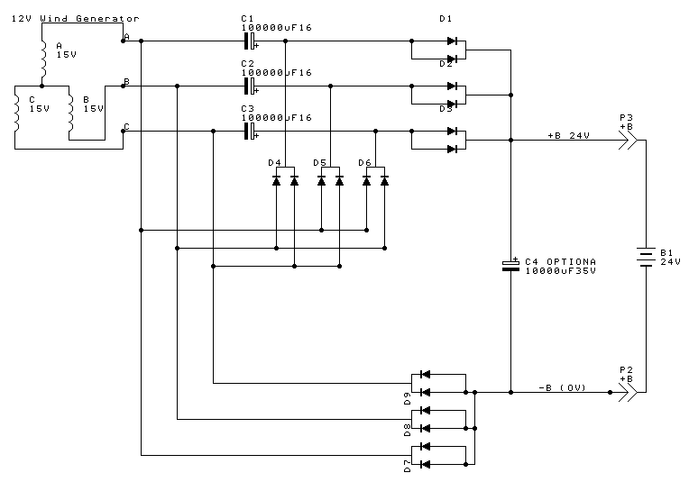
http://www.fieldlines.com/story/2006/6/19/143035/964 I searched for "3 phase voltage doubler" in google and found a few interresting circuits. http://home.earthlink.net/~jimlux/hv/cw1.htm http://www.reuk.co.uk/Three-Phase-Voltage-Multiplier.htm This last page has poor layout but lots of info. http://www.electrical-res.com/three-phase-voltage-multiplier / Glenn The best time to plant a tree was twenty years ago, the second best time is right now. JAQ |
||||
| Gizmo Admin Group Joined: 05/06/2004 Location: AustraliaPosts: 5078 |
This is a simple circuit, almost too simple. 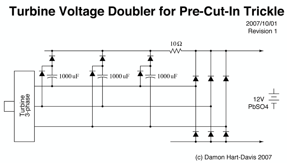
Glenn The best time to plant a tree was twenty years ago, the second best time is right now. JAQ |
||||
| Gizmo Admin Group Joined: 05/06/2004 Location: AustraliaPosts: 5078 |
I've redrawn the above circuit using bridge rectifiers. 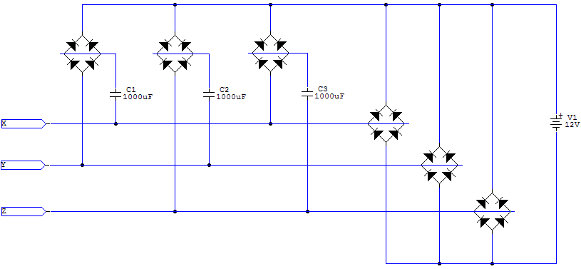
Uses 6 bridges, but each bridge is using its internal diodes in parallel for increased current capacity. This circuit above, ( drawn by Damon Hart-Davis ) also shows polarised capacitors. Now I have a feeling this type of voltage doubler can use polarised capacitors, and lower voltage than we have been using, so long as the mill is always loaded and never allowed to free wheel. The circuit a couple of posts up, posted by spacejunk, shows polarised caps rated at only 16 volts. If this is the case, then this type of voltage doubler would be very cheap to build. Glenn The best time to plant a tree was twenty years ago, the second best time is right now. JAQ |
||||
| KarlJ Guru Joined: 19/05/2008 Location: AustraliaPosts: 1178 |
OK, can one of you bright sparks please post an image of the voltage doubler and tripler arrangement in the Gordon/ OZ-Flux capacitor method? Oh and I read somewhere else that in the back to back cap idea it didnt matter if they were neg to neg or pos to pos, please confirm as it looks like I stuffed up and wired neg to neg. Luck favours the well prepared |
||||
| GWatPE Senior Member Joined: 01/09/2006 Location: AustraliaPosts: 2127 |
Hi Glenn, you missed the important resistor in this arrangement. As the mill AC increases to normal rectifier cutin, the caps will present a parallel load across the windings. The resistor prevents high currents, and is a loss. In the spacejunk cct, I see 100,000uF caps. These would present close to an AC short cct at even a modest 20Hz. I see voltage doubling, but the loading presented will not be optimum for the windmill in changing wind conditions. Arrangements with multiple seriesed caps present high impedance at low Hz and pass low power. OK for high voltage bias ccts. I have found an arrangement that can give a close to optimum windmill loading. Gordon. become more energy aware |
||||
| Gizmo Admin Group Joined: 05/06/2004 Location: AustraliaPosts: 5078 |
Yes your right Gordon, I did leave out that resistor, couldn't see what it was there for but now I understand. OK so it looks like the circuit I posted will work, but not as well as Gordons version. Hey Gordon could you post the web address of that Rocclby component supplier, looks like I wrote it down incorrectly when I was talking to you on the phone. I'll add it to the cap mod web page. Glenn The best time to plant a tree was twenty years ago, the second best time is right now. JAQ |
||||
| GWatPE Senior Member Joined: 01/09/2006 Location: AustraliaPosts: 2127 |
Hi Glenn, The web address is www.rockby.com.au Here are some pics of a cap voltage trippler and a cap voltage doubler that I recently assembled. I used the 270uF 450V doubler to get the measurements for Herb. This is the doubler. 270uF 450VDC caps with 25A 600V bridge rectifiers. This is the trippler. 100uF 400VDC caps with 25A 600V bridge rectifiers. With my arrangements there can only be a maximum 1/2 the AC windmill output voltage across the caps in a voltage doubler, and 1/3 the maximum AC windmill output voltage in a tripler. This reduces the stresses on the caps. Part of the more optimum windmill loading is related to not pushing the caps too far. Gordon. become more energy aware |
||||
| KarlJ Guru Joined: 19/05/2008 Location: AustraliaPosts: 1178 |
sketch of the tripler circuit anyone??? Karl Luck favours the well prepared |
||||
SparWeb Senior Member Joined: 17/04/2008 Location: CanadaPosts: 196 |
Would this be a correct diagram for a "Tripler"? 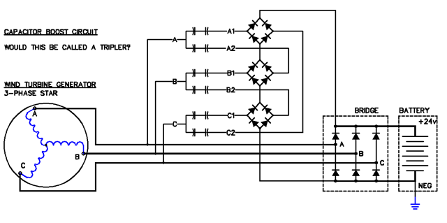
Is it possible to correct or delete this circuit diagram if it is wrong, in case someone comes along later and tries to build it? Yes Steven I can do that if required. Glenn. Steven T. Fahey |
||||
| GWatPE Senior Member Joined: 01/09/2006 Location: AustraliaPosts: 2127 |
Hi Sparweb, In a cap voltage tripler, I use 18 caps, DC type in the back to back arrangement. The arrangement is really 3 AC coupled series cap loadings with the rectified outputs placed in series, instead of 2 as in a voltage doubler. In my arrangement the phases are loaded equally in each cap section. I have been looking at the arrangement you have pictured above. You have non symetrical adding of the voltages in each rectifier block, but my testing still shows a voltage tripling effect. I am sure that there are many arrangements that will work. The output voltage was not as stable as with a full 3phase bridge arrangement, but this abridged version should still be OK for the low power that would be expected that the caps are required to pass. The individual capacitance for 12 caps in a tripler will need to be 1.5X the size of those used in an 18 cap arrangement to offer the same loading. The loading offered by the caps is determined by the capacitance, and the voltage developed across the caps. I would leave the cct as it does perform a similar function. Gordon. PS: As long as readers remember that the caps do not necessarily double the rated windmill power. The better loading offered to the windmill is the objective. become more energy aware |
||||
SparWeb Senior Member Joined: 17/04/2008 Location: CanadaPosts: 196 |
Thanks for the check Gordon. I want to model it with Spice and see what it says for various cap values. Now that I've drawn it myself I understand it a lot more, too. Steven T. Fahey |
||||
| GWatPE Senior Member Joined: 01/09/2006 Location: AustraliaPosts: 2127 |
Hi Sparweb, the current transferred by the caps as the frequency is increased is the key, into say a battery. Modeling the cap behaviour with AC and DC electrical aspects will be interesting. Gordon. become more energy aware |
||||
SparWeb Senior Member Joined: 17/04/2008 Location: CanadaPosts: 196 |
The genny I'm using is a 2-pole motor conversion. The only frequency I need to consider is "really low"!! 
My challenge is figuring out what cap value to use in between 3 Hz and 6 Hz. Just screaming along, eh? Steven T. Fahey |
||||
| GWatPE Senior Member Joined: 01/09/2006 Location: AustraliaPosts: 2127 |
Hi Sparweb, The frequency is not much different to my AxFx mill at cutin. 6Hz on my mill is 60rpm. Caps work no problems. You need to really know how much power the wind has available when the windmill is operating at the 3-6Hz. I would think that if the motor conversion would have an upper rpm of 360 and this was 2 pole then this would be 6Hz. My windmill would have approx 36Hz at the same rpm. The low Hz require approx 6X larger uF than my design. Low Hz is cruel. The Low Hz would allow for lower voltage caps, as a spinoff. Physically bigger caps have larger surface area so would operate cooler when passing the same power. There is such a difference to the 200Hz or so of a F&P at similar rpm. Gordon. become more energy aware |
||||
| GWatPE Senior Member Joined: 01/09/2006 Location: AustraliaPosts: 2127 |
just managed to test on a Mac. will replace with real post later Gordon link test become more energy aware |
||||
| KarlJ Guru Joined: 19/05/2008 Location: AustraliaPosts: 1178 |
Gordon, I omitted the 5W 10K resistor as on the input side I have the brake switches. Is this OK? Obviously as with any mill if the correct shutdown sequence is not performed there is risk to both electronics and turbine. EG shut down mill first, then turn off battery startup battery on the start mill etc. The dead short on the input to the caps will surely be a more rapid dissipation of any accumulated voltages./ Luck favours the well prepared |
||||
| GWatPE Senior Member Joined: 01/09/2006 Location: AustraliaPosts: 2127 |
Hi Karl, I don't have any resistors. Bleed resistors can be placed across pairs of back to back DC caps. DC voltage remains across the caps when the mill is shut down if they are not used. I use a resistor to remove the DC only when I work on a cap block OFF the windmill. When the mill stops with low winds, the windings effecticely short the cap cct inputs, but DC will remain across the caps. I have an automatic windmill shutdown relay that shorts the mill AC, in addition to the manual shorting switch. My mill can be shut down in any manner. The only protection I don't have is for a broken AC connection resulting in no loading, even when shorted. I would pick this problem up another way, with changed windmill power output characteristics. ie higher rpm for same power. Logging has benefits here. Gordon. become more energy aware |
||||
| JimBo911 Senior Member Joined: 26/03/2009 Location: United StatesPosts: 262 |
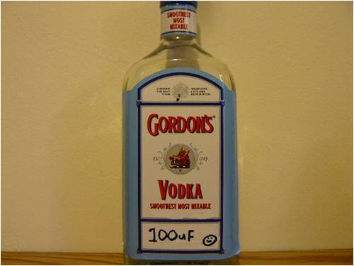
Jim |
||||
Downwind Guru Joined: 09/09/2009 Location: AustraliaPosts: 2333 |
It looks a little over proof  Sometimes it just works |
||||
| JimBo911 Senior Member Joined: 26/03/2009 Location: United StatesPosts: 262 |
What can I say?????  Jim |
||||