
|

|
Forum Index : Electronics : Inverter PCB’s
| Author | Message | ||||
| Phil23 Guru Joined: 27/03/2016 Location: AustraliaPosts: 1664 |
Hi Mad, Don't know the dimensions of the above board, but how would you gos spacing the screw terminals to match a breaker busbar, (18mm I think). Then the cable could be terminated to these. Cheers. Edit Now I think about it, it would even be possible to trim the end of the bar a bit & crimp it & cable in some copper tube or a joining link to keep some flexibility. |
||||
Madness Guru Joined: 08/10/2011 Location: AustraliaPosts: 2498 |
Hi Phil, I don't have room to move them any other way, it would be easy to drill a piece of copper to suite. This 3 X 15mm Copper Bar Could easily be drilled to suit the hole spacing required. But I think I would prefer crimping 6 smaller cables on the end of the main cable coming in from the panels and a round end crimp terminal on the end of each smaller wire. That would put much less stress on the board also. There are only 10 types of people in the world: those who understand binary, and those who don't. |
||||
Madness Guru Joined: 08/10/2011 Location: AustraliaPosts: 2498 |
Just added PCB-11 Screw Terminals to the 4 KW Inverter PCB for the negative connections. It still has the option to solder directly to the bottom also.  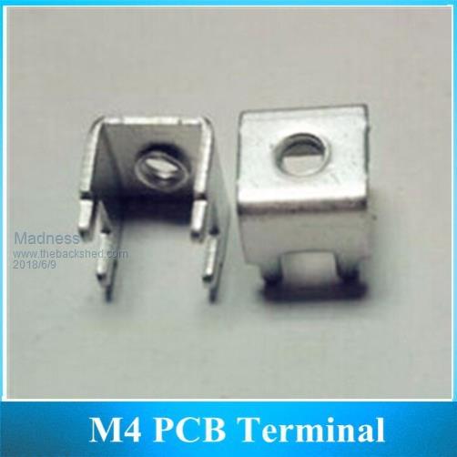 These are the 8MM long type there are others that are 11mm ones that won't fit. You can also find these on the Aerosharp PCBs but they are M3. 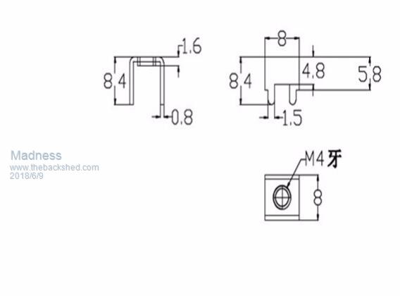 There are only 10 types of people in the world: those who understand binary, and those who don't. |
||||
renewableMark Guru Joined: 09/12/2017 Location: AustraliaPosts: 1678 |
I see they come in packs of 100. Maybe give an option to buy boards with the required amount of terminals for extra $ Cheers Caveman Mark Off grid eastern Melb |
||||
Madness Guru Joined: 08/10/2011 Location: AustraliaPosts: 2498 |
I have just ordered the terminals, $2 extra if you want them also. The ones I have ordered include the M4 screw as well. But you can use the ones out of the Aerosharp PCBs just that they are M3. There are only 10 types of people in the world: those who understand binary, and those who don't. |
||||
Madness Guru Joined: 08/10/2011 Location: AustraliaPosts: 2498 |
Anyone in Tasmania after Aerosharps? There are only 10 types of people in the world: those who understand binary, and those who don't. |
||||
| Phil23 Guru Joined: 27/03/2016 Location: AustraliaPosts: 1664 |
Other thought that came to mind regarding stress on the board was flat copper braid. No drilling, just a washer either side. Enough extra length for some flex & add a bit of sleeve. Don't see a problem with the 6 you mention above, just can't help thinking of possible alternatives.... Cheers. PS, I'm better off suggesting alternatives to the 6 smaller cables, that the Six or so herbs & spices going into tonight's dinner recipe..... |
||||
Madness Guru Joined: 08/10/2011 Location: AustraliaPosts: 2498 |
For those who are not confident with loading the program into the Nano I can supply them for $5 preloaded with the program for the regulator. There is one temperature sensor for the battery that is optional but it does not need it's address coded into the Nano. I have my latest update running with control of my battery vent fan and diverting excess power to my hot water system. The way this works is 0.7 volts under the setpoint (float or absorb voltage) the regulator starts sending a PWM signal to the solid state relay I have connected to the HWS. As the voltage rises the PWM increases to full power at 0.2 volts under the setpoint only then does the regulator start to reduce power input from the PV panels. The commercial charge controllers I have been using do this also, they call it "Waste Not" as it is diverting power that otherwise would go unused. On cloudy days it comes on partially as required. I have been using it like this for a couple years it puts as much power as possible into the hot water with little effect on battery charging. Next part I need to complete is monitoring battery current and limiting it if required. Phil I am sure people will use the method they prefer or what suits what they have on hand, I will just stick with the 6 wires crimped into lugs option myself. There are only 10 types of people in the world: those who understand binary, and those who don't. |
||||
Madness Guru Joined: 08/10/2011 Location: AustraliaPosts: 2498 |
Here is the final version of the Charge Regulator, I had some issues with the A3120 Isolated MOSFET driver on the DC to DC side dying due to overvoltage. So now it's 18V power supply is referenced from the PV panel negative rather than ground. When regulating the voltage of the PV panel increases and therefore the PV - goes below lower than ground (MOSFET Drains are connected to the negative side of the battery, Source to the panels). This was increasing the voltage across the IC to 40 or more volts. Now the 18V supply stays constant but is floating with the PV panel negative voltage below zero. The IC can operate up to 30V, there is also a 30V Zener across the IC to stop it going past 30V. Another change is I have added 2N2222 transistors to all the auxiliary output pins to step up the signals to 12v. The SSRs I am using are supposed to work from 3 volt but with PWM they need more kick, now with 12V it is sending excess power to the HWS as I expected it to do. There are 6.3mm spade connectors for the HVDC for the GTI side they are supposed to handle 20A and there 4 inputs and 4 out so should be no problems with them. On the DC-DC side there are 6 M4 Screw terminals which should handle up to 50 amps each so it should be possible to regulate up to 300A. That is well under what the MOSFETs will handle. The ground connects to the battery is via the heatsink with the HY4008 (or any other suitable N Channel MOSFET). If anyone else is interested in getting any PCBs please let me know ASAP, I am going to be ordering them tomorrow. 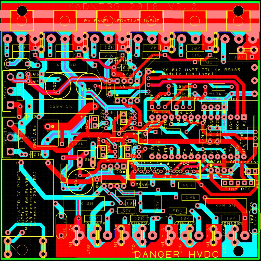 There are only 10 types of people in the world: those who understand binary, and those who don't. |
||||
| Ralph2k6 Senior Member Joined: 24/09/2017 Location: AustraliaPosts: 129 |
Put me down for 1 charge regulator please Mad. Ralph |
||||
| mason Regular Member Joined: 07/11/2015 Location: CanadaPosts: 86 |
Madness. Are they 10.00 USD each, will you send some to Canada? Mason |
||||
Madness Guru Joined: 08/10/2011 Location: AustraliaPosts: 2498 |
Prices are $10 AUD Mason, postage to Canada for up to 500g is $25 AUD. You could get 10 posted for that price. Here is what I have available $10 Regulator PCB Plus $2 for Terminals $95 Regulator kit for PCB and all parts on it and LCD not including current sensor($23 posted on Aliexpress) $5 Dual Fan Controllers $15 Inverter Control PCB $18 4KW Inverter Power PCB Plus $2 for Terminals $30 8KW Inverter Power PCB Postage in Australia is $15 up to 1KG and $17 for up to 3KG. I am happy to post anywhere in the world, just ask for a price. There are only 10 types of people in the world: those who understand binary, and those who don't. |
||||
| mason Regular Member Joined: 07/11/2015 Location: CanadaPosts: 86 |
Hi Madness, Is there a parts list for your new version of the charge regulator? Neil |
||||
Madness Guru Joined: 08/10/2011 Location: AustraliaPosts: 2498 |
I am working on the parts list, I will try to have it done today or tomorrow. There are only 10 types of people in the world: those who understand binary, and those who don't. |
||||
Madness Guru Joined: 08/10/2011 Location: AustraliaPosts: 2498 |
Here is the parts list for the regulator, I think it is complete. Just updated it, I had not included the LCD Display and battery temperature sensor. I have included links to the less generic parts to make it easier, they there for examples, you can buy them or the same from elsewhere. 2018-06-17_073341_Regulator_V2_Parts_List.zip I found one incorrect value on the silkscreen, 4K7 resistor in center top half of image in previous post should be 10K. There are only 10 types of people in the world: those who understand binary, and those who don't. |
||||
Madness Guru Joined: 08/10/2011 Location: AustraliaPosts: 2498 |
Here is a picture of the control board assembled for reference. 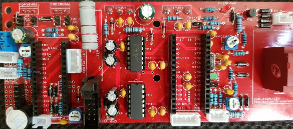 There are only 10 types of people in the world: those who understand binary, and those who don't. |
||||
Madness Guru Joined: 08/10/2011 Location: AustraliaPosts: 2498 |
I have had a few problems with step down voltage converters sending a spike through when turned on. I have killed a couple Arduinos due to this, to stop it happening put a 13V Zener diode across the 12V input of the Control Board with the banded end connected to the positive side. There are only 10 types of people in the world: those who understand binary, and those who don't. |
||||
| Tinker Guru Joined: 07/11/2007 Location: AustraliaPosts: 1904 |
How do you find those connectors (2-5 pin kit in your parts list)stand up to (ab)use?  . Just curious as the ones I use are different, yours seem to be smaller in height. . Just curious as the ones I use are different, yours seem to be smaller in height.I did wonder what these were called so I can look them up, now I know - Ali express. I buy mine individually from Altronics but such a kit as yours makes a lot more sense for the experimenter. They end up cheaper too. Did you buy a crimper too? Are the plugs & sockets marked for pin 1? I hope you do not mind my questions, I'm always keen to use something better. Klaus |
||||
Madness Guru Joined: 08/10/2011 Location: AustraliaPosts: 2498 |
This is the Crimper I use. If you get one you do need to follow the directions they give you. I have never had any problem with these connectors apart from not having the wire in the terminal properly when crimping. Once you put the crimped ends in they are very difficult to get out without wrecking them. The pins are not numbered, they can only plug in one way, there is zero risk of getting it wrong except if you have multiple connectors with the same number of pins you need to get the right one. 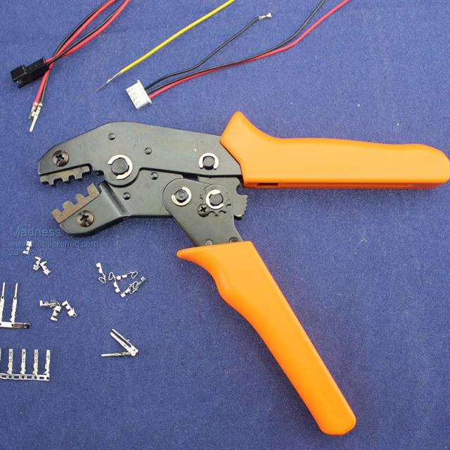 Plus you can get different jaws for crimp connectors etc. 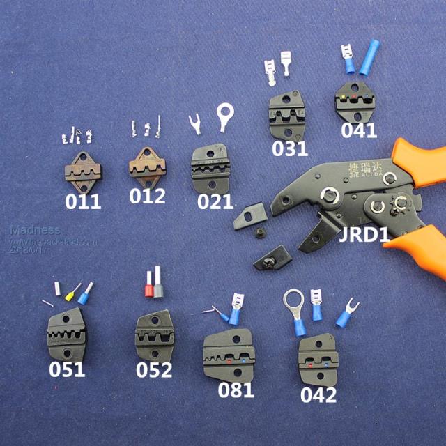 You can put them together without the crimper but it is more fiddly and the end result is not as good. If you plan to be playing with PCBs into the future it is well worth getting the right tools. There are only 10 types of people in the world: those who understand binary, and those who don't. |
||||
| Tinker Guru Joined: 07/11/2007 Location: AustraliaPosts: 1904 |
Thanks for all that info Gary, very useful for all using these connectors. Looking closely at the crimp inserts I see they have a retaining barb just like the Ouupin brand I have been using so far. With these, the 'barb' latches in an opening of the connector shell which is accessible from the outside. Using a very small flat blade jewelers screwdriver its easy to push the barb in and withdraw the crimped connector & wire. A sharp knife blade resets the 'barb' and the crimped connector can then be re-inserted in the correct slot. Can you do that with your connectors? I ask that in case I change over, I am using shells with up to 12 pins and sometimes start to push the crimp connectors in from the wrong end  . The crimping tool I have is non latching but I think it would do the job for the connectors you use. . The crimping tool I have is non latching but I think it would do the job for the connectors you use. Klaus |
||||