
|

|
Forum Index : Electronics : 8 KW Inverter Build
| Author | Message | ||||
| Mulver Senior Member Joined: 27/02/2017 Location: AustraliaPosts: 160 |
Thanks Madness, software is Autodesk Inventor 2016 I believe silly expensive for personal use, but its supplied by work. I did my trade using Unigraphics NX3 10 years ago, but sketching in most CAD software that I have used appears to be similar. Having said that I grabbed the Intern this morning to give me a quick 2 min lesson on copying the winding around the radius X number of times  |
||||
Madness Guru Joined: 08/10/2011 Location: AustraliaPosts: 2498 |
When I made my Toroid I used Rhino CAD (free 30 day trial) to make a paper disc giving me the right position for each turn. I put it under the Mylar before winding the winding the wire so I had the spacing correct. 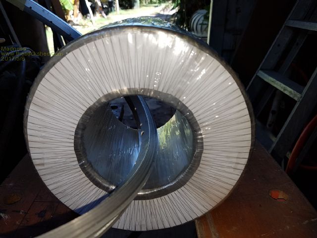 If you do wind it that way you should wind on a layer of Mylar after you do the first round as you will have half of you AC voltage difference between each inner and outer turn. There are only 10 types of people in the world: those who understand binary, and those who don't. |
||||
| Mulver Senior Member Joined: 27/02/2017 Location: AustraliaPosts: 160 |
Yeh I thought a nice thick layer would be advisable. Did some testing on 4 x 500 mm lengths twisted 16 turns it sprung back 1/2 a turn after twisting. lost 10mm in length.      |
||||
Madness Guru Joined: 08/10/2011 Location: AustraliaPosts: 2498 |
It has been 1 month since I commissioned the big Inverter with the TIP transistor gate drivers and it has been running continuously since then. Not one hiccup, it's been a long road to get this point but I am very pleased with the outcome. Thank you to everyone who has assisted me with this and in particular a very big thank you to John Tulloch AKA Oztules. The 5 KW GTI is working well also, I have 5 KW of panels connected to it but half of those are on the ground as the weather has not allowed me to get them up on the roof yet. So far it has not got over 3KW and already I have power to spare and we have had some rainy days. So far the HWS has taken up the extra power with my charge controllers turning it on when absorb/float voltage is reached but with a few fine days it will be getting to full temperature and turning off. With the GTI connected the Inverter spends most of the daylight hours working backwards, this means that most of the time it is not working hard and with full sun and heavy loads the Inverter will not be doing much more than keeping the GTI happy providing it with 50HZ to sync to. Even on cloudy days, the GTI is powering the normal 250 - 500 watts to the house keeping fridges etc running. As the GTI is 98% efficient (at least that is what the specs say) it is producing the maximum watts possible from the available light. So I was wondering John if you had any success with the IGBT's between the panels and a GTI? There are only 10 types of people in the world: those who understand binary, and those who don't. |
||||
oztules Guru Joined: 26/07/2007 Location: AustraliaPosts: 1686 |
Struggling to find time to scratch myself at the moment, so no have not done so yet. New boards will be working tonight or tomorrow..... testing seems good thus far. Very nice to see your unit is working without fuss.... well done. ..........oztules Village idiot...or... just another hack out of his depth |
||||
Madness Guru Joined: 08/10/2011 Location: AustraliaPosts: 2498 |
Just been trawling the net for information about IGBTs and came across this information about how to connect an Aero-sharp to your computer. Someone may find it useful you can see it here. There are only 10 types of people in the world: those who understand binary, and those who don't. |
||||
Madness Guru Joined: 08/10/2011 Location: AustraliaPosts: 2498 |
I have now set up the 5KW of panels I recently bought, these have replaced a 2.8KW array that I had in the location. 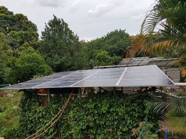 I have 9.5KW of panels now, as yet I have not had a really sunny day since setting up the new 5KW array, most I have seen is 3.5KW on the GTI connected to the new panels with about 3 KW back feeding through the inverter. Now I need to work on controlling the excess power I am getting on sunny days. I am very happy with how the inverter is just running without fuss both powering the house and back feeding charge into the batteries from the GTI. There are only 10 types of people in the world: those who understand binary, and those who don't. |
||||
oztules Guru Joined: 26/07/2007 Location: AustraliaPosts: 1686 |
That may lend itself nicely to fet driven string shut down... ie sequentially shut off one string at a time etc based on battery volts and current. I am crying in my beer looking at what you mainlanders get for $700.... wow. ..........oztules Village idiot...or... just another hack out of his depth |
||||
| Mulver Senior Member Joined: 27/02/2017 Location: AustraliaPosts: 160 |
This has been my research topic for the last few weeks! I am only at the toroid winding stage but Im trying to plan ahead what ill do. I remember oztules stating he can waste ~75kw on a good day, due to low loads and plenty of sun!GTI's turn off etc. This started me thinking what can we use this power on! My thoughts ATM... Sun comes up batteries charge back up and then you have excess to burn. Turn on hot water, modulate a SSR to consume the excess until its not needed or there is too much excess. Thats pretty straight forward nothing complicated. Arduino Battery Voltage Controlled Relays Next biggest consumer is Heating/Cooling! Im in SA so its AC in summer and wood fire in winter, problem is the wood fire is terrible for the environment, for my asthmatic wife, and cost me 2k a year in wood. As much as we love the wood fire long term i would like to only use it occasionally not as primary heating. So in winter (we plan on renovating) Underfloor radiant heating in as many places as possible and wall mounted radiant heating elsewhere. ALL controlled via the excess power available. With intent to heat soak the house (while not in it) to hold the heat in the slab and walls etc. We have a mud brick house so it holds its temps for up to 3 days before outside extreme temps starts to be felt inside.This will hopefully be enough to have the house comfortable and not require heating overnight. So far pretty straight forward I think Next is Summer the dreaded AC, I plan on installing a ducted inverter AC and i would like to be able to control it in the same manner as heating! Vary the power is consumes to the excess thats available. Problem is AC's are way more complicated than an element. But i stumbled on the below thread. Daikin SKYFi Api They gain control of the AC via sniffing out the IP traffic to an web based control. This to me seems reasonable that we could monitor, the outside temp, the inside temp, and the excess power available. Then send commands to the AC to various set points dependent on these variables. Taking it a step further if you logged the outside temperature, you could swap automatically between heating and cooling dependent on the average temperatures. And if you had WAY to much excess power you could run the AC on heat mode and the floor heating at once! Sauna anyone?  |
||||
Madness Guru Joined: 08/10/2011 Location: AustraliaPosts: 2498 |
Whoops, I forgot about that Arduino thread, I need to complete it. Here is my thoughts regarding the extra power and what to do with it. At present, I have 2 Midnite charge controllers that have 2 auxiliary controls each, one is simple on off with set points and the other is PWM. Eventually, I will be replacing the Midnites with a DIY controller that is based on an Arduino, this would allow a lot of flexibility. I use the on off AUX of the Midnite CC to switch on my HWS element when absorb or float voltage is reached for 30 seconds and will stay on until 10 minutes after the the voltage falls below the set point. I was running this previously off PWM which does not work so well with the GTI connected to my DIY inverter. What I have considered is to also run the AC with the on off state and a time delay. I think most AC's will come back on to the last state is was in if the power is disconnected. If you leave the AC set to auto and an appropriate temperature it could come on and run, if there is plenty of power it will stay on, if not it will turn off again after the delay time has elapsed. This is all okay but eventually you will find yourself in a situation where you still have too much power and need to throttle back the panels. If my solar HWS temp is down after a day or 2 of cloudy weather it soaks up the extra power for a day or so but the thermostat clicks off and the battery volts climb too high with the 5KW GTI. What I am working on is using one or 2 of the IGBT's and the board that attaches to them from the Aero-Sharp Inverters to control the connection from the solar panels to the GTI. By using PWM to control this it could supply the right amount of power required and no more. I would still try to utilise as much power as practical and still divert power to the HWS and AC. I may be completely wrong here (I am no electronics guru, just feeling my way around in the dark) but if I connect the panels to the IGBT as per this diagram I can control both PV array's to the GTI with a bank of capacitors across each output to smooth out the DC. 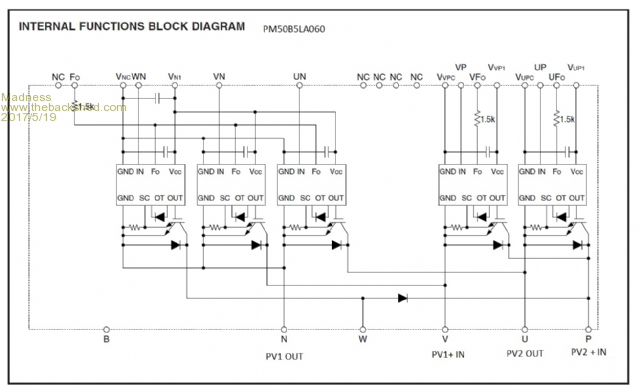 This is the opto isolator board that comes with the IGBT 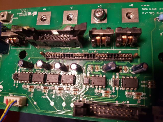 The isolator chips are 2017-05-19_042919_AV02-0867EN_DS_HCPL-4504_2014-01-070.pdf 4504 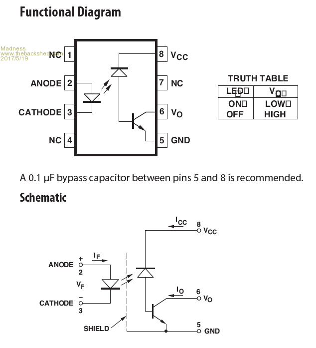 I think all need to do is supply the correct voltages to the PCB and 5V across pins 2 and 3 to turn it on the IGBT. As yet I have not worked out the supply voltages but I see pin 8 of the isolator require 30V. The Arduino circuit from the thread mentioned in the previous post could be used to control it and it will be very easy to program charging times and voltages for absorb and float with the Arduino microcontroller. There are only 10 types of people in the world: those who understand binary, and those who don't. |
||||
| Mulver Senior Member Joined: 27/02/2017 Location: AustraliaPosts: 160 |
Very interested in how you go with that Madness! I was playing with my growatt 4200 gti and an inverter generator. Testing for the next blackout! Anyway, what I noticed was even though the sun was shining well on the 1.5kw of panels when the gti connected to the genny. It slowly ramped up the power.... not a sudden shove of power I was expecting. The genny just slowly backed off as the gti ramped up. I'm assuming it's doing its mppt thing up to the best it can find. Surely someone (much smarter than me) would be able to trick the gti to control the power. I assume it uses reference voltage to do calculations could we maybe intersept and modify. |
||||
Madness Guru Joined: 08/10/2011 Location: AustraliaPosts: 2498 |
I have Wednesday to myself so will work more on it then, been catching up a little on other things that were forgotten about with the inverter build. I did see somewhere a SMA (could be wrong) AC coupled system that stopped the GTI by varying the frequency of the OGI to cause the GTI to shut down due to the frequency being out of range. Seems a bit of a clumsy way to do it especially for a manufacturer. One possible way to fool the GTI is to play with the current\voltage sensing on the output, that may cause it to throttle back a bit but it may not get the point of shutting it down. The MPPT itself would be would be all software and hard to figure out even if you could get into it, possibly playing around with it's sensing of PV voltage could be a possibility too, Today was mostly sunny and once again I was making more power than needed even with the hot water element on, tomorrow the HW will probably shut down due to being quite hot already. I have a spare inverter generator with a blown inverter, I have thought about just using its generator with a rectifier and capacitors to feed DC into a GTI. There are only 10 types of people in the world: those who understand binary, and those who don't. |
||||
Madness Guru Joined: 08/10/2011 Location: AustraliaPosts: 2498 |
I have seen a few sets of 5KW for $1,000 but that is the first time I have seen them that cheap. Just sheer luck, I had even deleted the email from Gumtree for them before reading properly. Something said hang on I need to look at that email. That combined with the $5 5KW GTI from the tip that is running perfectly is just a fluke that I will probably never repeat. There are only 10 types of people in the world: those who understand binary, and those who don't. |
||||
mackoffgrid Guru Joined: 13/03/2017 Location: AustraliaPosts: 460 |
Madness; This is a great idea. I'm going to give this a go. How much length did you lose when you twisted the 8m lengths? |
||||
Madness Guru Joined: 08/10/2011 Location: AustraliaPosts: 2498 |
When you twist it there is probably less than 300mm but I would allow 500 to be on the safe side. There are only 10 types of people in the world: those who understand binary, and those who don't. |
||||
mackoffgrid Guru Joined: 13/03/2017 Location: AustraliaPosts: 460 |
Thanks Madness This question may seem obvious, forgive me, but I'll ask anyway, you did run the wire though a straightener first? Are there any tricks to stripping the enamel off? Just sandpaper was my guess. Thanks Andrew |
||||
Madness Guru Joined: 08/10/2011 Location: AustraliaPosts: 2498 |
Hi Andrew, Yes, I straightened the wire, if not the kinks are going to make it into a bulky rats nest. As for stripping the enamel off the wire, I find a sharp cutter is very good for scrapping it off, much quicker than sand paper IMO. Another trick I found is a pair of wire strippers I have that have 2 V-shaped jaws a bit like a parrot's beak with an adjustable stop, set it to the right depth and draw it off the end with abut 4 or 5 strokes at different positions. There are only 10 types of people in the world: those who understand binary, and those who don't. |
||||
| Warpspeed Guru Joined: 09/08/2007 Location: AustraliaPosts: 4406 |
All excellent advice. My favorite method of copper wire straightening is to anchor one end in the bench vise, run the whole length out across the back lawn, and just stretch it tight. You will feel it stretch slightly and not spring back. All the bends and wobbles will then be gone. Cheers, Tony. |
||||
Madness Guru Joined: 08/10/2011 Location: AustraliaPosts: 2498 |
To get the sharp kinks out of the wire from the Aero-Sharp toroids I have found they have to go through 3 bearings to get them straight. Or perhaps Warp you live in a better paddock than me, although I doubt it. There are only 10 types of people in the world: those who understand binary, and those who don't. |
||||
| Warpspeed Guru Joined: 09/08/2007 Location: AustraliaPosts: 4406 |
You should not have any sharp kinks to begin with ! If you do then a very gentle un-kinking is called for. If a kink is pulled tight, you are in trouble. My advice only works with wire that has been very gently removed and very gently treated. The problem with copper is that it very readily work hardens. Every time it is bent and un-bent it gets stiffer and becomes much more difficult to work with. Cheers, Tony. |
||||