
|

|
Forum Index : Electronics : building an Inverter from scratch
| Author | Message | ||||
| Tinker Guru Joined: 07/11/2007 Location: AustraliaPosts: 1904 |
Tony, you never fail to amaze me with your explanations, I wish I was that clever. So, in your words, what will I see on the oscilloscope screen when the choke starts to saturate? Is the "ramp" doing a sharp turn upwards as the current is no longer limited by the choke? I think that is what happens but please correct me if necessary. So, for example, if I want a choke good for 5KW (~100A @ ~50V battery) where on that ramp should that 100A fall? Just before the upward turn? a long way before it? It might be a few days before the new PCB is ready, lots of other jobs to attend here. Klaus |
||||
| Warpspeed Guru Joined: 09/08/2007 Location: AustraliaPosts: 4406 |
The slope of the ramp will tell you the inductance directly. The lower the inductance, the faster rising and steeper the slope will be. So as we approach saturation, the inductance begins to fall away, and the until now linearly rising ramp begins to gradually curve upwards into a kind of "rhino horn" shape at the top. Some materials have a very soft saturation characteristic. The curve bending upward stars out almost imperceptibly and gradually gets steeper. Other materials abruptly saturate at a very specific level and there may be a very sharp angular upward change in the direction of the slope. One you have seen this its a very distinct change in upward slope, you cannot miss it. I am thinking your new monster choke is going to go to several hundred amps and you probably are not going to see any saturation effect before your tester blows up or you wisely back off. That is not a problem. Just rewind it with a great many more turns just for the test, maybe ten times as many turns. The actual number is not important. Then repeat the test. If it now saturates at 35 amps with 100 turns, you then know 10 turns on that exact same core will get you to 350 amps. You can use fairly skinny wire to do this, it only has to run for a few seconds for a quick test. The magic number is ampere turns to saturation. Once you know that, its simple to scale the core saturation current for any number of turns. Those original inverter chokes often have about 80 turns and easily go to over thirty amps. Say 2,400+ ampere turns easily. Ten turns maybe about 240 amps as a wild guess possibly even 350 amps. Stacking two cores as you have done will double the inductance, but both cores will still saturate (together) at the same current. Anyhow I reckon your new monster choke should do very nicely. Cheers, Tony. |
||||
| poida Guru Joined: 02/02/2017 Location: AustraliaPosts: 1418 |
Here is what saturation looks like: 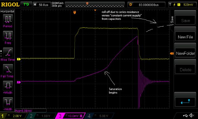 One part of the (pink) curve rises at a low rate, then it changes to a faster rate of climb when saturation is becoming prevalent. Yellow is mosfet gate drive, pink is current, approx 1mV / Amp In my tests I frequently find inductors level out at some sort of current. In the case of the above, it's at about 45 Amps. This is due to series resistance of the circuit (inductor ESR plus mosfet Rds(on) plus wiring plus capacitor ESR) wronger than a phone book full of wrong phone numbers |
||||
| Warpspeed Guru Joined: 09/08/2007 Location: AustraliaPosts: 4406 |
That final leveling out effect appears to be the power source dying in the bum. If you build a ramp up / ramp down type tester, the current keeps rising at an ever increasing rate until mosfet turn off. But your waveform does illustrate the point of the smoothly rising ramp, and the initial upward bend very nicely, which is the point we are interested in. Cheers, Tony. |
||||
| poida Guru Joined: 02/02/2017 Location: AustraliaPosts: 1418 |
power source dying in the bum = significant power source impedance I hinted at this with the sum of (inductor ESR plus mosfet Rds(on) plus wiring plus capacitor ESR) wronger than a phone book full of wrong phone numbers |
||||
| Warpspeed Guru Joined: 09/08/2007 Location: AustraliaPosts: 4406 |
Yes, "dying in the bum" is indeed a technical term suggestive of series impedance as you did originally point out. That is the big advantage of the ramp up / ramp down tester. It stores up energy and recovers almost all of it, so its never caught short when pushed really hard. The current can readily spike up to destructive levels long before it rolls over, so it can give a much more dramatic display of the effect of saturation. My camera died some time ago, which makes all this much more difficult. I will soon be in the market for a replacement camera, and am really impressed with your screen shots. What camera and lens are you using ? Cheers, Tony. |
||||
| poida Guru Joined: 02/02/2017 Location: AustraliaPosts: 1418 |
Warp, the DSO captures are direct to USB thumbdrive via the DSO front panel buttons. No optical process at all. This results in PNG files which I can upload to the forum without any processing needed. The camera I used for the photo of the air core inductor (in another post) is a Canon G15. I like these a lot, I've had a few point and shoots and this is a good one for my needs (HD video of 40 minute basketball games from one battery charge) I also have Canon 20D with a few lenses, including the EF 100-400 4.5-5.6 L IS II which is sensational for birds. wronger than a phone book full of wrong phone numbers |
||||
| Warpspeed Guru Joined: 09/08/2007 Location: AustraliaPosts: 4406 |
I have been looking at some of the lower to mid range Cannon cameras on e-bay. There are so many different models, its difficult to know what to do. Cheers, Tony. |
||||
| Tinker Guru Joined: 07/11/2007 Location: AustraliaPosts: 1904 |
Thanks for the excellent explanation Tony and also Poida for the pictorial explanation. My 'test choke' can easily be rewound with more turns of thinner wire which I will do shortly. As it is, with 10 turns, my inductance meter said its 86uH. Today I did a bread board test of the 4066 schematic Solar Mike posted. With the values given it generated 50 HZ to 2.6KHz square wave pulses. All nicely adjustable, thanks for 'convincing' me this is a better approach. The PCB etching starts tomorrow. I wish I had a DSO but cannot justify getting one. The idea of getting the captured screen directly onto a USB stick is brilliant. I always wondered how Poida got these sharp images. Klaus |
||||
| poida Guru Joined: 02/02/2017 Location: AustraliaPosts: 1418 |
Right now the DSO I use is available from Eyou for $570 plus gst. I bought mine from them when they cost $440 years ago. I also have a Rigol DS2072 2 channel DSO, actually better than the 1054Z. Maybe I could loan Tinker or Warpspeed this one? Once you use a DSO for this sort of work, you wont want to give it back. This is a risk I can take here. Freight via TNT or IPEC won't cost much more than $35 from capital city to capital city along the East coast. What's your thoughts on this? I see the cost of this gear as part of my ongoing education. wronger than a phone book full of wrong phone numbers |
||||
| Warpspeed Guru Joined: 09/08/2007 Location: AustraliaPosts: 4406 |
For everyday use I prefer a fast analog scope, I recently purchased a Tektronix 2445B. This is 200 Mhz four channel and was the last analog scope Tek ever made, and arguably the best. The full service manual is available on the internet, and spare parts are still readily available. Made in the mid 80's and now available for less than 1K for a well preserved example, and about half that for one thats a bit rough but fully functional. Also from the mid 80's I recently purchased a Tektronix 2430, this is a 100 Mhz two channel digital scope. This was the very first digital scope ever made by Tektronix and one of the first (if not the very first) digital scope on the market anywhere. Back then nobody had any real idea of how the user interface of a digital scope should be presented. The controls are a bit quirky, and there is a steep learning curve, but it does some pretty remarkable things if you can get used to driving it. It also uses a CRT not an LCD display. It was a revolution in its day, and $75,000 dollars was a lot of money back in the 1980's. You can get one today for about $500 or slightly more. Packed full of 74LS logic chips in dual in line packages, with through hole circuit boards. Its still repairable, and the full service manual is available for it on the internet. Since those days, several things have changed. The Japanese and Chinese started copying Tektronix circuits, so Tek stopped making the full service manuals available for all their oscilloscopes, which makes anything later than mid 80's essentially unrepairable. The 2430 was just too good and too expensive, so later models had far less features to reduce the cost. The price war brought the cost of digital scopes came right down and now everyone uses LCD displays and surface mount chips, and no circuits are ever released by anyone. Once your new digital LCD scope is out of warranty it is unrepairable. Fortunately they are mostly very reliable. But you could still be unlucky... So for me, the old stuff is large and heavy, but its also repairable. And its cheap for the performance and the features. I still prefer to use the analog scope. But there are some things that only a digital scope will do, such as seeing events leading up to the trigger point, and capturing one time events. Or for anything really slow. Cheers, Tony. |
||||
| Warpspeed Guru Joined: 09/08/2007 Location: AustraliaPosts: 4406 |
I just found a small yellowing piece of paper with curled corners, which was my original test result of an Inspire 1.5Kw choke. With 30v applied it ramped up to 28 amps in 3.5mS where it then started to saturate, indicating 3.75mH. This choke has two 42 turn windings in series giving 84 total turns. One turn would give 3750uH / 84 x 84 = 0.531uH Ten turns 0.531 x 10 x 10 = 53.1uH. But as you have stacked two core sets, that would double that inductance to 106uH Hence my "guess" of about 100uH. I am assuming the Chinese all copy each other, and that these various chokes, "Inspire" "Aerosharp" and possibly others are all pretty close to each other in design. If the guessing game continues, then 84 turns and 28 amps gives 2,352 ampere turns. So ten turns on the same core should get you to 235 amps. Anyhow, 86uH is not too far away from 106uH, considering its not Inspire cores you are using. I would expect the saturation figure you finally end up with may also come reasonably close to 235 amps. I think this is going to be be a very nice choke. Cheers, Tony. |
||||
| Tinker Guru Joined: 07/11/2007 Location: AustraliaPosts: 1904 |
Thanks Tony, my tinkering about the core saturation will hopefully confirm your original tests. Its all good fun and I learn a bit (actually a lot!) along the way. There is no way my 10KW lithium battery bank could sustain 235 Amps for any length of time. Also, the 6 x HY4008's might protest as well. Anyway, I won't be able to fit more than 7 turns of 2 x 20mm sq on that core if I use stranded cable. I could have fitted more turns using my 3x5mm enameled wire but I would have had to do that before I epoxied the core halves together. Klaus |
||||
| Warpspeed Guru Joined: 09/08/2007 Location: AustraliaPosts: 4406 |
Seven turns should just about halve the 86uH, which should still be o/k. Its not that critical, but more is better. If you can squeeze in an extra turn with slightly thinner wire it would not hurt. Cheers, Tony. |
||||
| naiclub Newbie Joined: 07/09/2016 Location: ThailandPosts: 6 |
This is a superdrive module kit. 3-layer system EG8010 prevent damage Low battery stopped working. Battery charge is higher than set to stop working. Overload stopped working. I am on trial  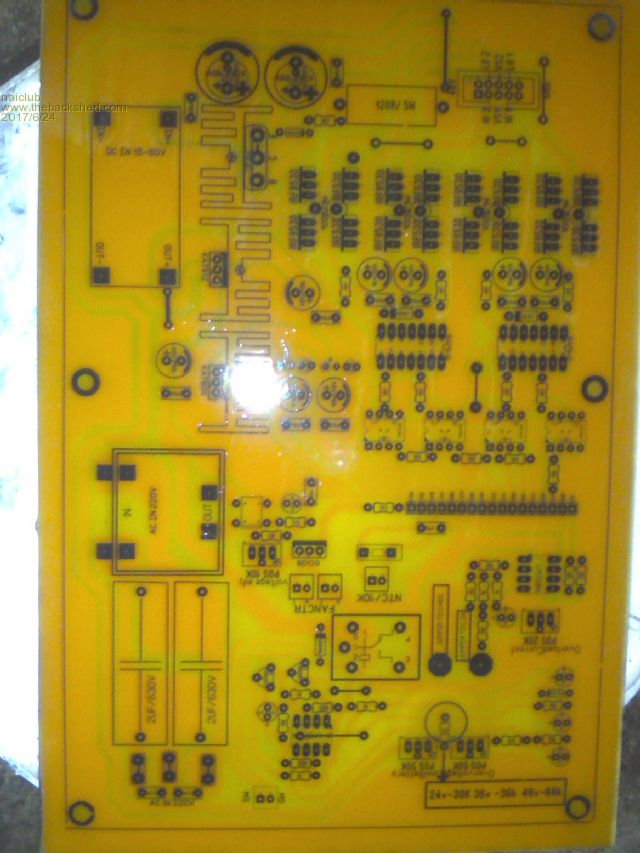 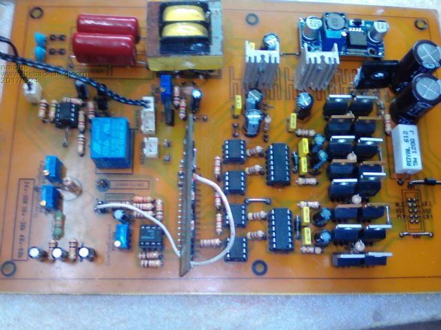 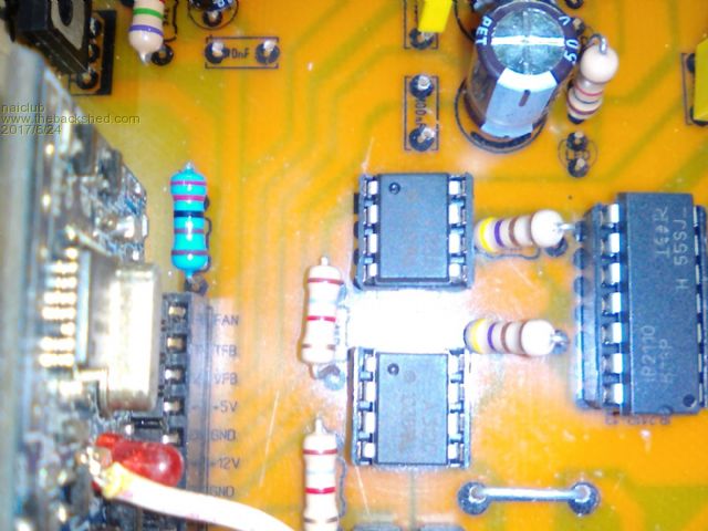 |
||||
| Tinker Guru Joined: 07/11/2007 Location: AustraliaPosts: 1904 |
Naiclub, your post *really* should have been put under its own thread, not added to mine. Its not nice to clutter my thread up with completely irrelevant pictures of whatever you are doing. This is known as hijacking a thread, not nice! You are welcome to comment on this thread if it is relevant to "building an inverter from scratch" and it refers to whatever I or others have posted on these 33 pages. Yes, there is the occasional off topic banter, that's OK, but pictures of some kit with no explanation why are not. Klaus |
||||
| naiclub Newbie Joined: 07/09/2016 Location: ThailandPosts: 6 |
Thanks for the advice. And apologize for not knowing about it. And sorry about my ignorance. |
||||
| Tinker Guru Joined: 07/11/2007 Location: AustraliaPosts: 1904 |
After Solar Mike has been doing some choke saturation testing I just had to try that myself  The approach was a bit different, I split the circuit into a driver PCB and a power PCB. That used up some small PCB offcuts and also made the connecting a little easier, IMO anyway. Here is a picture of the test set up: 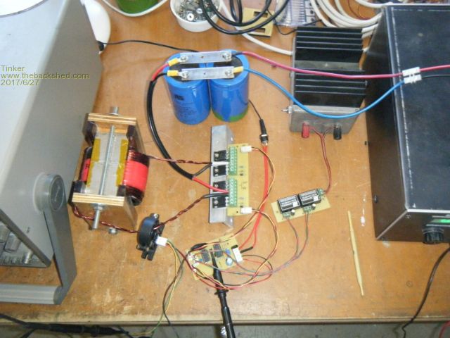 And another, showing details better: 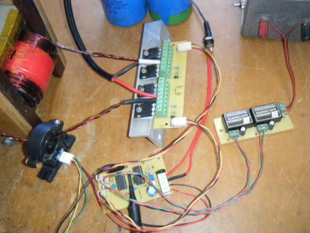 Testing was done with my choke (2 x C ex Aerosharp)cores epoxied to a plywood backing and hardwood side bits. This made a very strong 2 piece core assembly, which let me easily insert the wound coil and also change the air gap spacers. The coil was wound from recycled 1.8mm dia wire (2.5mm sq) which I wound on 2 in hand, simultaneously. I did this on the lathe, manual powered chuck and the tool post clamping the wires to wind with an even strain. 125 turns were wound on, why 125?. I had two skeins of 500g wire and these gave 125 turns 2 in hand  . .Test 1 with a 2x 0.8mm gap (laminex pieces) got to saturation at 10A, giving 1250A/t Test 2 with a 2 x 1.2mm gap (plastic sheet) got to saturation at 12.5A, 1562.5A/t Test 3 with a 2x 1.7mm gap (original gap spacers) got to saturation at 20A, 2500A/t All tests were done at 52Hz. Here are a couple of CRO pics - sorry about the poor quality. Pic just before saturation: 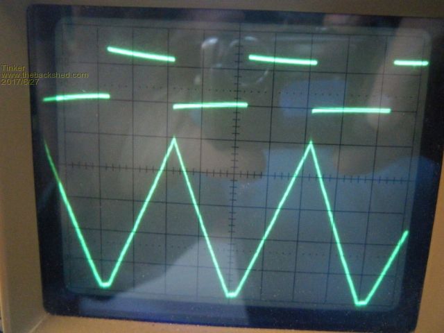 And this one with saturation: 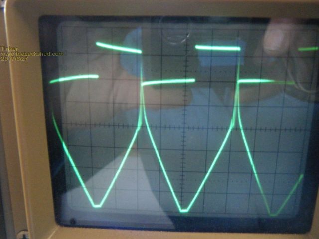 Its quite obvious when saturation occurs, the noise from the coil also changes. Note, the pics are not with the same air gap. These were just the clearest pics of the bunch I took  Nothing got even remotely warm even when left running close to saturation for a while. The trace is also nice linear, which I like. So these cores seem to be suitable. They are made of a quite flakey material, not laminations, so I epoxy coated them to prevent material coming off each time they got assembled. From the above results the following coil will be wound shortly: One layer would accommodate 18 turns of 1.8mm dia wire, wound two in hand (5 mm sq). A total of ten layers would give me 18 turns of 50 mm sq. This would fit nicely and give me the maximum copper/ turn ratio for that core. I shall find out what inductance that makes when its finished. 18 turns would saturate at 138A, that's almost 7.5KW from my battery bank and a power level that I don't plan to get near once that inverter is finally running. My thanks go to Warpspeed and solar Mike for their valuable contributions with this choke core saturation testing. Klaus |
||||
| Warpspeed Guru Joined: 09/08/2007 Location: AustraliaPosts: 4406 |
O/k got that Klaus. On time pretty close to 9mS I think. Twenty amps peak. 125 turns. What was the applied dc voltage for that ? Cheers, Tony. |
||||
| Tinker Guru Joined: 07/11/2007 Location: AustraliaPosts: 1904 |
Ha, did not write that down Tony. I'll repeat the test tomorrow and note all the details. Klaus |
||||