|

|
Forum Index : Electronics : Inverter PCB’s
| Author | Message | ||||
renewableMark Guru Joined: 09/12/2017 Location: AustraliaPosts: 1678 |
Sorry mate, I'm trying to get my head around what it can do. (It's a unique product) So it can be used for PWM solar controller. Or a GTI controller that will limit the voltage feed into the mini grid to prevent batteries from cooking. And it can be set to either have an isolated ground (aerosharp etc), or connected ground depending on whether you have a transformer type inverter or not. If you use it as a GTI controller then you need a separate one for that if you also want to do PWM solar also yeah? Cheers Caveman Mark Off grid eastern Melb |
||||
| ryanm Senior Member Joined: 25/09/2015 Location: AustraliaPosts: 202 |
Thought about doing that, but for the tiny price of the components on aliexpress I figure may as well do it once and right. No such thing as an underloaded FET. (As far as I know) |
||||
Madness Guru Joined: 08/10/2011 Location: AustraliaPosts: 2498 |
You can use it as a basic PWM LV controller direct to the battery, you can also use it to regulate a GTI as you described or both at the same time. The side of the PCB with 6 MOSFETs can do your LV PWM and the other side with 4 Isolated 600V Mosfets will regulate the GTI. All at the same time, so theoretically you could have 10KW of LV DC to DC panels and a 5 KW GTI with 7KW of panels connected to it. Sounds like overkill but combine that with a current sensor to your battery and you will be able to limit the charge current to a safe level for the battery. That way you can have plenty of PV panels for when the weather is bad and tame it down when the sun is out. The current limiting will just be controlling what is going to the battery. If you want to have ACs and the clothes dryer on when the sun is shining you will still have the power available it is only the battery current that needs controlling. There are only 10 types of people in the world: those who understand binary, and those who don't. |
||||
Madness Guru Joined: 08/10/2011 Location: AustraliaPosts: 2498 |
The limiting factor is the transformer, my 8KW Inverter can be back feeding at 5-6 KW and not heat up the heatsinks enough to bother turning on the fans. Meanwhile, the Toroid is getting up a little over 50 degrees with it's fans on full tilt. I have the case configured with the fans at the top and bottom and there is good convection air flow. So even though the fans are not on there is a steady flow of warm air coming out the top. But when the Inverter is running off the battery the heatsinks do heat up more than the transformer runs cooler. At least this is one advantage of having accurate temperature sensors and displaying the temperatures on the display. The code I have written also keeps the maximum temperature on the display. So far the heatsinks have not been above 40 and the toroid 55 degrees. I changed the temperature settings to 40 and 50 degrees, originally they were 35 and 45. There are only 10 types of people in the world: those who understand binary, and those who don't. |
||||
Madness Guru Joined: 08/10/2011 Location: AustraliaPosts: 2498 |
Here is some of the less obvious parts required for the charge regulator. You may be able to find individual ones, I normally buy multiples of everything. Isolated PSU (must have for HF GTI's) 16 Bit Analogue to digital converter this gives much better resolution for voltage and reading the current sensor. Hall Effect Current Sensor 15 Volt power supply You will need one of these power supplies to step down the 48V supply to 15V for the current sensor, there are cheaper ones but they don't go up to voltage level required for FLA on Absorption charge at 63V. RS485 Module Not needed at all unless you want to have master and slave units. Also, I will be using this in the future for data logging. An old grid tie inverter case with a big flat heatsink at the back is ideal to put the regulator in. There are only 10 types of people in the world: those who understand binary, and those who don't. |
||||
| yahoo2 Guru Joined: 05/04/2011 Location: AustraliaPosts: 1166 |
 I have been thinking about it for 3 months now. I think it should be able to drive a DC forklift motor, those things last for decades and they are cheap. there is a lot of petrol motor driven equipment that could be converted to electric. the 240v ac to 3 phase variable frequency drives get a bit sketchy above 3 kw so I have been looking for an alternative, I really think big ol DC motors on a battery pack are the solution. I am waiting for a guy called Damian to post a video demonstrating how to tune "ringing" out of the square wave with a few resistors and I should be right to have a go myself. I'm confused, no wait... maybe I'm not... |
||||
| Warpspeed Guru Joined: 09/08/2007 Location: AustraliaPosts: 4406 |
That would make a lot of sense for the normally very power frugal "off gridders" that wish to very occasionally drive a high powered air compressor or a fire pump for example. Cheers, Tony. |
||||
Madness Guru Joined: 08/10/2011 Location: AustraliaPosts: 2498 |
Many of us on here would have contributed a little to help a Chinese company get into the worlds top 10. There are only 10 types of people in the world: those who understand binary, and those who don't. |
||||
Madness Guru Joined: 08/10/2011 Location: AustraliaPosts: 2498 |
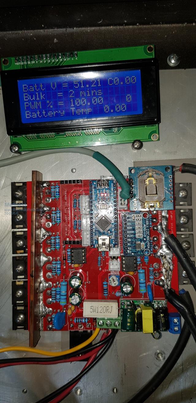
I have assembled the new version of the charge regulator but have run out of time today to test it. It will need to wait to the weekend now to try it out.  There are only 10 types of people in the world: those who understand binary, and those who don't. |
||||
| Tinker Guru Joined: 07/11/2007 Location: AustraliaPosts: 1904 |
Neat PCB board Gary but a little compromised by the direct soldering on of those big black wires. Doing that is very tough on the track underneath, from a mechanical and heat stress during soldering point of view. Can I suggest, for your next board layout  to provide an area to bolt on cable lugs directly to the board or, if room is short, have a right angle copper bracket that bolts to the PCB at that track and then you can bolt on several solder lugs to the raised end of that copper bracket. to provide an area to bolt on cable lugs directly to the board or, if room is short, have a right angle copper bracket that bolts to the PCB at that track and then you can bolt on several solder lugs to the raised end of that copper bracket.I should think a copper strip 25mm x 1.6mm should do to make neat high current connecting lugs. You can see a real high current version of this on a picture of my inverter, used to connect the negative rail to the PCB. I think even oztules now uses this method, from what I spotted on his pictures. Klaus |
||||
Madness Guru Joined: 08/10/2011 Location: AustraliaPosts: 2498 |
Trouble is getting bolts through the pcb when you have tracks the other side. I have yet to see a failure soldering directly to the PCB. There are only 10 types of people in the world: those who understand binary, and those who don't. |
||||
Madness Guru Joined: 08/10/2011 Location: AustraliaPosts: 2498 |
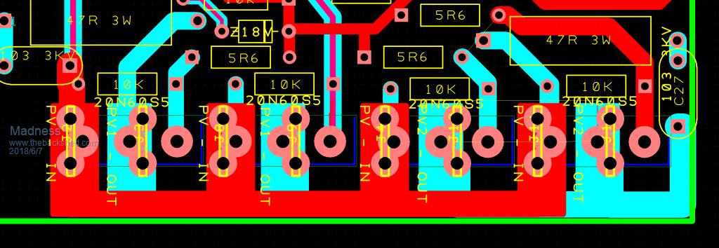
I have worked out a way to improve the connection of the DC from the PV panels for the GTI. I have changed it to 6.3mm spade terminals right next to the MOSFET legs, as the MOSFETs are on the bottom side of the PCB and flat against the board this means there will be no interference between the 2.  The other side will have to remain as it is for the high current for low voltage DC to DC as the current is much too high for the 20A limit of spade terminals. I have used 15 X 3 MM copper bar with M4 threads, it is quite easy to attach to the PCB, just file clean the edge. I put solder on the PCB first and then heat the copper with a Butane gas torch and tin the edge. While the copper is hot just place it on the PCB in the right spot. It melts the solder on the PCB, then just keep it in place until it cools enough for the solder to harden. This does not put excess heat on the PCB, it is best to do it after the MOSFETs are installed otherwise it is hard to solder them as the copper draws away the heat. There are only 10 types of people in the world: those who understand binary, and those who don't. |
||||
| Solar Mike Guru Joined: 08/02/2015 Location: New ZealandPosts: 1138 |
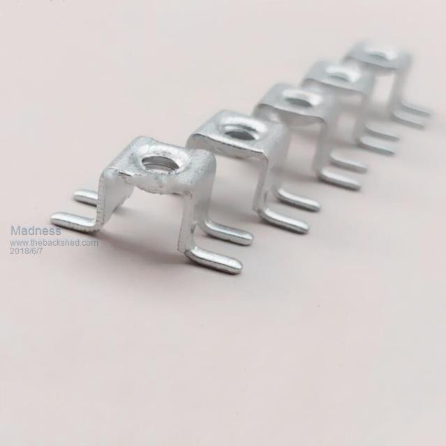
These terminals work quite well High Current PCB Terminal, the M5 ones come up sometimes, 40 - 80 amps should be ok. Cheers Mike |
||||
Madness Guru Joined: 08/10/2011 Location: AustraliaPosts: 2498 |
Thanks Mike, that is very helpful, even found a 180A M8 Version. I had thought of using the M4 ones that are on the Areosharp PCBs but could not find a source, now I know what they are called it is easy to find and buy them if needed. There are only 10 types of people in the world: those who understand binary, and those who don't. |
||||
| Tinker Guru Joined: 07/11/2007 Location: AustraliaPosts: 1904 |
Thanks for taking up this suggestion Gary, a well worth while addition, especially to people who might not have much experience with high current connections. That 180Amp terminal would do well on your inverter PCB, one at each end would give a choice for connecting the negative cable. Klaus |
||||
Madness Guru Joined: 08/10/2011 Location: AustraliaPosts: 2498 |
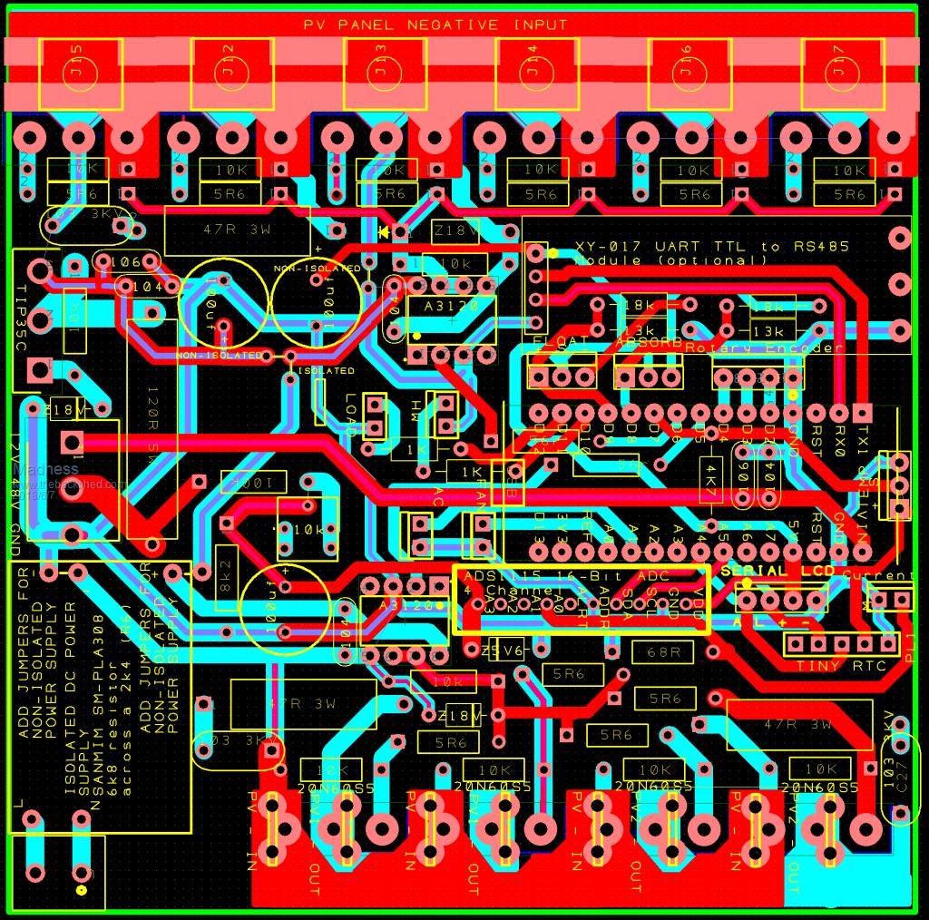
Inverter PCBs are not something I am doing anything with ATM, however I don't think one connection is going to be a good idea. Having to rely on the PCB copper to conduct across 300MM is stretching it a bit, I will look at something with multiple connections. I have made further changes to the Regulator PCB to include these SMD Terminals .  They are almost identical to the ones in the Aerosharp PCBs except they are M3 and through hole. I have checked and it easy to bend them to the same as the photo above. Being SMD made it much easier than trying to use through hole, that would have required a major increase in PCB size. Six of them fit across nicely with just 0.2MM overhang, the output is via the heatsink. So those plus the Spade Terminals on the HVDC side eliminates heavy soldering on the PCB and can still take big currents.  There are only 10 types of people in the world: those who understand binary, and those who don't. |
||||
| Ralph2k6 Senior Member Joined: 24/09/2017 Location: AustraliaPosts: 129 |
Looking very nice there Gary. Steady progress.  Ralph |
||||
Madness Guru Joined: 08/10/2011 Location: AustraliaPosts: 2498 |
Thanks Ralph, Should be ready to order PCBs sometime next week. I just need to confirm I have got everything right for the current sensing. I will just clarify what they will do, they can be used as a basic charge control regulator for a GTI (any size 1 or 2 Channels I am running 7KW of panels) back feeding through your inverter. That is handled by the 4 20A 600V MOSFETs on the bottom of the PCB, the 6 200A 80V MOSFETs on the top side will regulate DC from PV to your batteries by PWM. The best panels for this are those that have a maximum power voltage just over 30V, so running these in strings of 2 gives maximum power around 61V. There is virtually no losses with this regulator, you don't get MPPT (the GTI will have it) but what you save in the cost of the regulator will buy you a lot more panels to make up for it. This Regulator will handle at least 10KW of panels going DC to 48VDC. You can use just a GTI or just DC to DC or both giving a possible 20KW capability. You might think you will never have that many panels but secondhand panels are getting cheaper all the time, I recently saw someone selling 30KW of 250-watt panels for $30 each and less for bulk buys. There is no such thing as having too many panels when it is cloudy you can still get plenty of power if you have enough panels. Where it could be a problem is putting too much power into your batteries when the sun is bright, so I am also using a 300A Hall Effect Sensor to monitor battery current. This will then allow limiting the battery current to a suitable level for your batteries. Also it will be used to give you a battery state of charge reading which is particularly useful for people that don't understand how it all works but just want to know "How Much Power is in the batteries". Other things it will do is regulate another GTI via a second PCB set up as a slave (same PCB with less components and different program) up to 1.2KM away via twisted pair wires, turn on a HWS when there is excess power, control a battery vent fan, control a dump load and more. The regulator PCB's will be $10 each, also I am going to be ordering 4 KW Inverter PCB's will be $18 each, I did say $17 before but there has not been a lot of demand. Regulator PCBs $10 each 4KW Power Boards $18 each 8KW Power Boards $30 each Inverter Control Boards $15 each Dual Fan Controller Boards $5 Express Post up to 1 KG $15 within Australia, if you are International let me know I work out a price. Please PM me if you want to confirm your order. There are only 10 types of people in the world: those who understand binary, and those who don't. |
||||
renewableMark Guru Joined: 09/12/2017 Location: AustraliaPosts: 1678 |
Hey if you just intend to use it for a solar controller is it a good idea to have a separate one for east/west? Cheers Caveman Mark Off grid eastern Melb |
||||
Madness Guru Joined: 08/10/2011 Location: AustraliaPosts: 2498 |
It should not matter Mark, it is not MPPT and simply connects the Panels directly to your battery. When your battery voltage increases to Absorb the regulator then reduces the amount of power going to the batteries to maintain the Setpoint, the same applies once it goes to float. If you are planning to use multiple GTI's then yes you will need more. There are only 10 types of people in the world: those who understand binary, and those who don't. |
||||