
|

|
Forum Index : Electronics : VFD Running off Inverter
| Author | Message | ||||
Madness Guru Joined: 08/10/2011 Location: AustraliaPosts: 2498 |
Got the 2 speed motor out, bloody pain in the arse to work on, I had to modify tools to get the Allen screws out that held it in. The stator is out now and all the wires are buried between the windings, hopefully, I can pry them apart enough without damaging the windings. If all else fails I will just rewind it, I did my 8KVA generator a while ago, it is a 12 wire stator and that was more complicated than this motor. 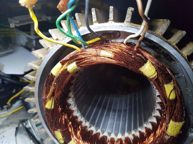 Tony I have seen VFD's like this up to 7.5KW designed to run off single phase, a 10A GPO is not going to handle that. There are only 10 types of people in the world: those who understand binary, and those who don't. |
||||
oztules Guru Joined: 26/07/2007 Location: AustraliaPosts: 1686 |
You should only need to use the wires coming from the motor.. you should not need to open the motor up Look at the wiring diagram you supplied.. it is a 4 pole to 2 pole iteration.. it should be simple to do. Warp. look at that diagram of the igbt... any two input to any of the 3 ph input will yield the 340v.... up to 4kw from that inverter mad built...... So mad, you should not have to open it up, just rewire the inout as i suggested above... it should yield 240v delta @ 240v full power as your right side diagram said. you should be able to get up to 3kw or more..... use the ramp to your advantage. You don't need to get to 6000rpm too fast, just take it steady. You can also wire it for 4 pole, and wind the hz up to 100 if you want. Warp, I was running 6kw for 5-10 mins today as I noticed the washing machine with heating, the hot water heater, and the electric jug with 2 lts were all running at the same time....and the house base load... so 3kw is a walk in the park for the mad inverter I suspect .....oztules Village idiot...or... just another hack out of his depth |
||||
Madness Guru Joined: 08/10/2011 Location: AustraliaPosts: 2498 |
Sorry, Oz did not read your post properly earlier, I was rereading it and had planned to ask about it. So what you saying is to effectively short one coil on each leg of the Delta windings? Motor is 1420/2710 RPM 1.6/2.2 KW Would bypassing half the coils reduce it's power capability? There are only 10 types of people in the world: those who understand binary, and those who don't. |
||||
oztules Guru Joined: 26/07/2007 Location: AustraliaPosts: 1686 |
No Mad look at your pic here 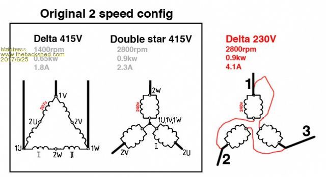 Look at your double star....... keep looking..... now make it delta???? done!!!... do not look at the delta 415v pic..... look at the center pic and the right pic... penny dropping now.... Look at the thing I said about connections.... 1W-2V then 1V-2U then 1U-2W.... same as delta 230v one. The coils stay the same as the diagram, but you simply go from star to delta. NO COILS ARE SHORTED It is the same power, near twice the current as star... you have said so in the third ( Right hand side) pic...... and it can be done without removing the motor at all. ie 1U,1V,1W and 2U,2V and 2W come out at the connection block do they not? ......oztules Village idiot...or... just another hack out of his depth |
||||
Madness Guru Joined: 08/10/2011 Location: AustraliaPosts: 2498 |
Yes 1U,1V,1W and 2U,2V and 2W come out however they are hard wired as per the Delta drawing on the left, to increase speed 2U, 2V and 2W are shorted to make the Double star. But to get the result on the right 2 U must be disconnected from the coil going to 1V, then that coil is connected to 2V etc as per the diagram below. The red X is where the wire needs to be disconnected as 2U is permanently connected to each coil above and below it. Same for 2V & 2W. 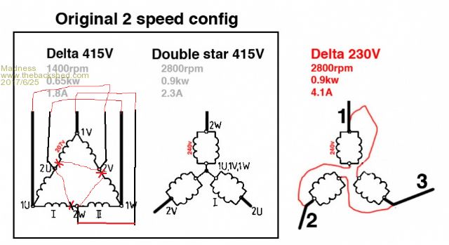 If it was wired this way it would be possible to change externally. 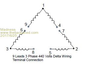 Here is a really oddball video that explains how the motor is wired from the factory. If you watch it you will think it is not about anything electrical but the guy in the video is obviously very clever but very unusual. There are only 10 types of people in the world: those who understand binary, and those who don't. |
||||
oztules Guru Joined: 26/07/2007 Location: AustraliaPosts: 1686 |
Sadly for you... i see what you mean. At least the input wires will show where the joins are, so should be easy task. ........oztules Village idiot...or... just another hack out of his depth |
||||
Madness Guru Joined: 08/10/2011 Location: AustraliaPosts: 2498 |
It is all disassembled apart from wedgeing apart the coils to get the leads out, that is the part the that worries me the most, I don't want to create any shorts in there. For a machine that is 32 years old it surprised me that the motor looks like brand new inside. There are only 10 types of people in the world: those who understand binary, and those who don't. |
||||
Madness Guru Joined: 08/10/2011 Location: AustraliaPosts: 2498 |
In case anybody in the future is looking at doing the same, I just realised the modification diagram is incorrect. The double star is effectively turned inside out when compared to the Delta 415V. So I have redone the modification diagram, coils with the red line through them need to be cut at the red line and reconnected as per the blue lines. 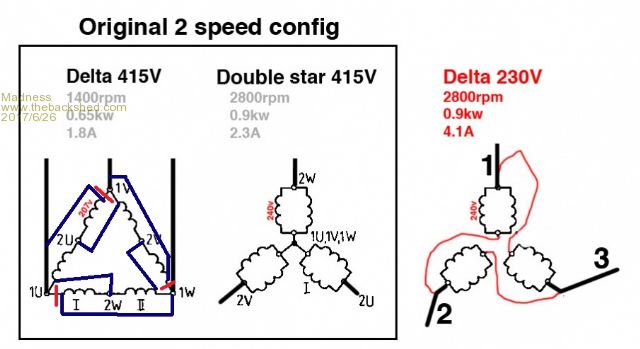 There are only 10 types of people in the world: those who understand binary, and those who don't. |
||||
Madness Guru Joined: 08/10/2011 Location: AustraliaPosts: 2498 |
The VFD arrived today, the 172 page manual is going to take some digesting. There are only 10 types of people in the world: those who understand binary, and those who don't. |
||||
| Warpspeed Guru Joined: 09/08/2007 Location: AustraliaPosts: 4406 |
Hopefully most of the default settings should not need changing, and it should be able to at least do something straight out of the box. Having now been through all this myself several times, it is going to take quite some time to wade through the jungle. But there will be a lot of very useful stuff in "the book of words" well worth knowing about. Cheers, Tony. |
||||
Madness Guru Joined: 08/10/2011 Location: AustraliaPosts: 2498 |
Success rewired the 2 speed motor as per the last drawing and wired the VFD to the rotary switch and everything works perfectly. Most settings are the default, the main one I had to change was motor speed parameters. Fortunately, all the three motors are 2 pole, spindle motor did switch between 2 and 4 pole before but now it is a double delta 2 pole. To run at the lower speed as per original can be done on the VFD. Still have it on the default ramp up and down time of 10 seconds. As yet I have not been able to put any load on the motors. There are only 10 types of people in the world: those who understand binary, and those who don't. |
||||
| Warpspeed Guru Joined: 09/08/2007 Location: AustraliaPosts: 4406 |
Well done ! Just double check everything turns in the right direction. That can sometimes be dangerous with woodworking machinery if its wrong. Do you have a good dust extractor blower and filter ? Cheers, Tony. |
||||
oztules Guru Joined: 26/07/2007 Location: AustraliaPosts: 1686 |
"Still have it on the default ramp up and down time of 10 seconds" I think thats not a bad thing. There are no prizes for high speed start up, just driving things hard for no gain.... both the inverter and the vfd. Nothing gained by a fast start that I can tell. Well done. .........oztules Village idiot...or... just another hack out of his depth |
||||
Madness Guru Joined: 08/10/2011 Location: AustraliaPosts: 2498 |
Everything turns the right way, that was just pure luck but got it right first time on all 3 motors. As yet I have not connected any start-stop switches or the kill switch to stop anyone switching motors while it is running but that will be done next. I need to find out about the internal brake resistor to see what it will handle for an emergency stop. A couple days ago I bought a blower for a jumping castle for $25 to make a dust extractor. It has a 400W motor and moves a lot of air, hopefully it is enough to do the job. The plan is to make a cyclone mounted on top of a 200L drum with a clip on air tight lid. I am hoping piping the exhaust far enough away will be okay for the very fine dust that gets past the cyclone. There are auxiliary control signals available I will use that to automatically start the extractor when the machine is running. There are only 10 types of people in the world: those who understand binary, and those who don't. |
||||
| Warpspeed Guru Joined: 09/08/2007 Location: AustraliaPosts: 4406 |
The internal braking resistor should be well up to the job, as it only has to work for ten seconds maximum at a time for the full rated Hp of the VFD. Usually there are terminals for fitting an external higher power braking resistor, but I have never ever seen this feature used. And I have seen a lot of VFDs when my day job was repairing them. I might suggest the internal resistor should be quite sufficient for what you are doing. Its highly likely that the internal braking resistor has a temperature sensor which will bring up an error message if it ever gets really unhappy. I once thought of building a large cyclone myself onto a drum as you are doing. I rescued a Dyson vacuum cleaner from the tip just to measure up their cyclone and see exactly how they did it. These Dyson vacuum cleaners do not use a bag like other vacuum cleaners. The cyclone is so good it filters everything out right down to microscopic dust and pollen, and returns the air to the room. Never built my own large cyclone, but still have the very small plastic Dyson one around here somewhere. Its a real work of art. Cheers, Tony. |
||||
Madness Guru Joined: 08/10/2011 Location: AustraliaPosts: 2498 |
This machine has 3" dust extraction ports, a vacuum cleaner just would not be up to it. Especially the 10" planer which does make a lot of shavings. One thought I have had is to have fine water mist in the last section of the pipe if dust does become a problem. There are lots of videos on Youtube of people building extractors with 20L plastic buckets and vacuum cleaners. Most claim to only get a very tiny amount of dust past the bucket cyclone. I plan to build a cone type with at least 450mm diameter at the top that I hope will be even more effective I only plan to use the braking for emergency stops, so the resitor will only have to deal with one stop. If it was used for every time the machine is turned off it would get quite a workout. There are only 10 types of people in the world: those who understand binary, and those who don't. |
||||
| Warpspeed Guru Joined: 09/08/2007 Location: AustraliaPosts: 4406 |
Definitely agree a domestic vacuum cleaner would be a complete joke for a woodworking machine. I only wanted to see how Dyson designed their cyclone. Its not that complicated, and could easily be scaled up into a sheet metal design that could be pop riveted or spot welded together. Its mainly a case of getting the proportions and angles right. This was all many years ago. These days there are plenty of ideas for building a large workshop cyclone on the internet. Cheers, Tony. |
||||
Madness Guru Joined: 08/10/2011 Location: AustraliaPosts: 2498 |
A vacuum is sufficient for most saws and hand held tools. I have a Triton workcenter that works fine with a vac. There are only 10 types of people in the world: those who understand binary, and those who don't. |
||||
Madness Guru Joined: 08/10/2011 Location: AustraliaPosts: 2498 |
Today I picked up a treadmill for free on Gumtree, took the cover off the motor and there is nice 2.2KW 3 phase motor and a VFD. I intend to use the treadmill for what it was designed to do but thought I would pass this on if anyone spots one of these things and could use such a motor and controller. I have heard of some treadmills using a scr controlled motor etc, I was quite surprised to see this nice setup, it would be really good for a drill press or small lathe. There is a linear actuator that raises and lowers the angle of the machine that could be very useful also. 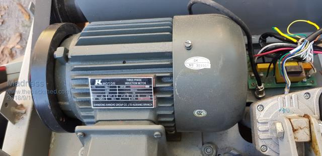 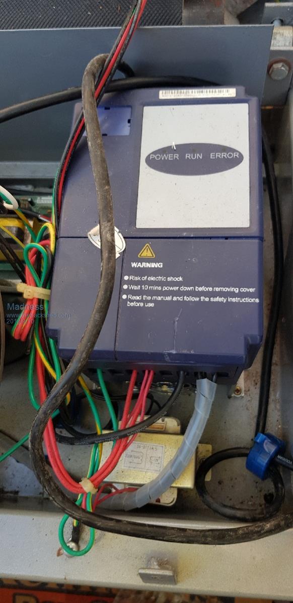 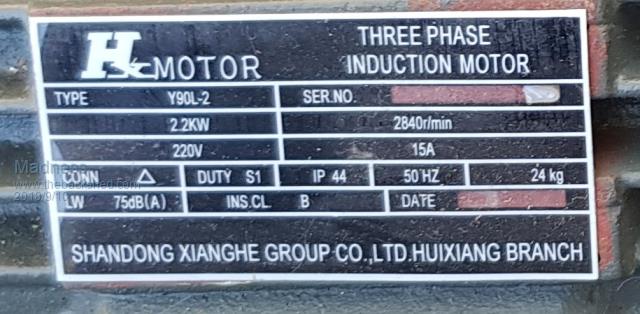 There are only 10 types of people in the world: those who understand binary, and those who don't. |
||||
| Warpspeed Guru Joined: 09/08/2007 Location: AustraliaPosts: 4406 |
[quote]it would be really good for a drill press or small lathe.[/quote] The problem with using a VFD on a drill press or a lathe is that it will certainly slow the speed right down almost to zero, but you don't get any extra torque multiplication at the reduced speed. If you use gears or pulleys to drop the speed in the usual way, that also multiplies the torque which is often as important as the reduced speed. A VFD could still be very useful, especially with a foot pedal, but it will never replace really low gearing. For very large hole saws and monster drills I built this: 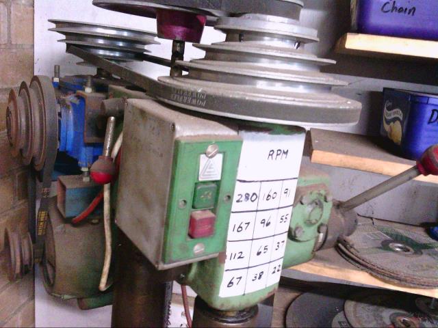 The blue thing at the back is a 10:1 worm drive right angle gearbox. With the two sets of cone pulleys I can get down to 22 RPM. Cheers, Tony. |
||||