
|

|
Forum Index : Electronics : Grogster’s Inverter Attempt.....
| Author | Message | ||||
Grogster Admin Group Joined: 31/12/2012 Location: New ZealandPosts: 9308 |
Here is my updated power board, based heavily on what I saw Tinker doing in this thread. 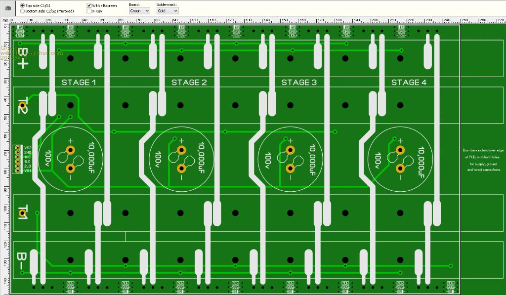
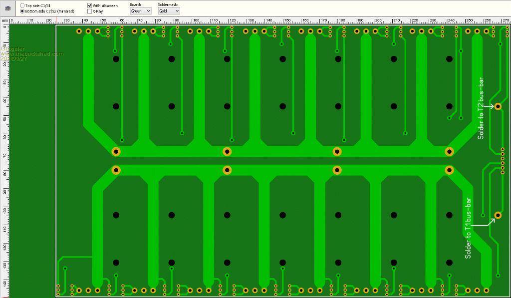
This new version drops the brass bus-bar idea, and replaces that with 20mm x 3mm copper bar as the bus-bars, and all MOSFETS are on the one common board along with the 10,000uF caps - no more modular thinking, no more then ONE board. The links from the MOSFET legs to the T1 and T2 bars are via 3mm solid-copper rod bent to the correct shape to clear the bus-bars they are crossing. I could make this 6mm solid copper rod if anyone thought that 3mm was too wimpy. 20mm x 3mm copper bar should be good for hundreds of amps of current no problem. 3mm solid round should be good for about 70A or so, which should be plenty for the individual legs of the FETS. The concept being that you solder the FET to the PCB, and the gate is taken care of with the PCB layout, and 3mm copper rod links then branch off for the T1 and T2 connections, and are soldered onto the correct location, so there can be no movement and therefore no kind of I2R heating if the joint was not mechanically bolted down right. The B+ and B- bus-bars have the legs of the FETS joined to the bus-bars also with the same 3mm solid copper rod for grunt. I quite like this one, and it has a fourth stage when I was only planning to use three, so four stages of HY4008 in TO-247 package should suffice I would hope. Smoke makes things work. When the smoke gets out, it stops! |
||||
Madness Guru Joined: 08/10/2011 Location: AustraliaPosts: 2498 |
I am about to use some copper sheet I have to make an overlay to go on the PCB to compliment the PCB copper. I will put holes in various places to solder it to the PCB and then drill for the MOSFET connection and solder as normal. My reason for doing that way is I am using virtually the same design as the Clockman boards and the copper sheet will fit under the caps across the bridge. Copper 0.5 mm thick by 100 mm wide is 50 mm square so it will carry heaps of current. There are only 10 types of people in the world: those who understand binary, and those who don't. |
||||
| Tinker Guru Joined: 07/11/2007 Location: AustraliaPosts: 1904 |
Hi Grogster. I have moved on from the layout you linked to above. Its much more compact now. Perhaps you might consider the very high currents flowing in and out of those big capacitors. I think the tracks on your PCB to them look a bit whimpy to my liking. FYI, I have my caps soldered directly to 25 x 1.5mm copper busbars. Klaus |
||||
Grogster Admin Group Joined: 31/12/2012 Location: New ZealandPosts: 9308 |
Tinker - what are you using now then? Can you please link me to what you are now using, so I see how you are currently doing things. I was wondering about the tracking to the caps. I think I will make it all copper plane to spread the load around there, and just have some cut-outs where the other tracks are. EDIT: Made the changes. 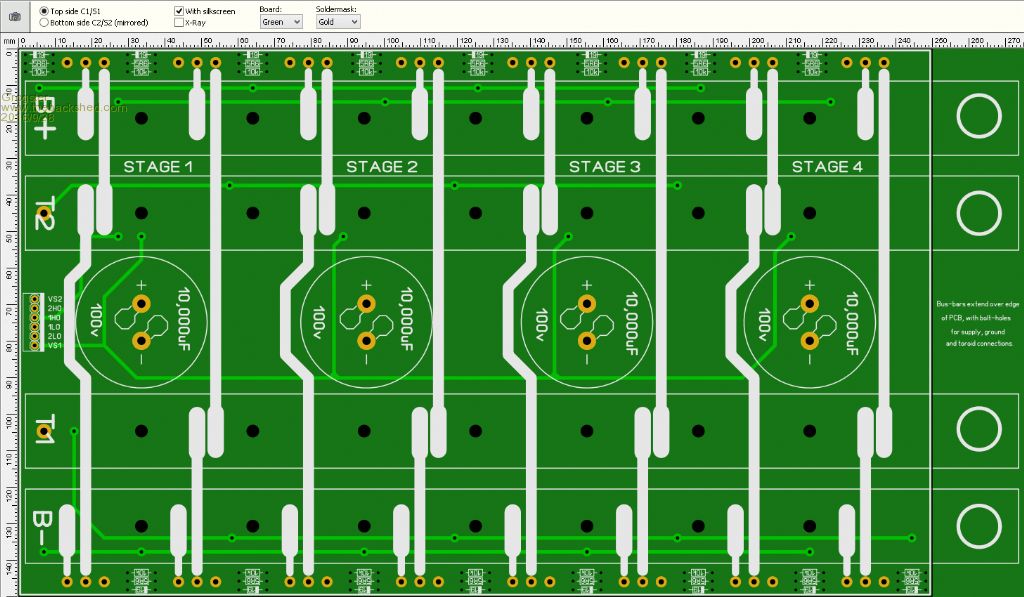
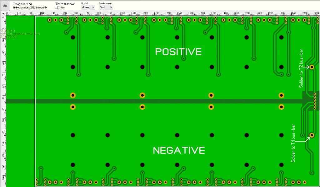
EDIT: Found Tinker's new more compact layout here. Smoke makes things work. When the smoke gets out, it stops! |
||||
| Tinker Guru Joined: 07/11/2007 Location: AustraliaPosts: 1904 |
Yes, that's the one I'm playing with at present. But this might change too, I'm having too much fun tinkering with that stuff. Your tracks look much better for the job now. The reason I use all busbars is that I etch my own boards and they are just single sided 1oz copper. Way too thin to carry much current no matter how wide the track is. I assume you are using plated through holes with that fancy PCB layout. You might like to make the Cmos pads as big as practicable (elongated) and not too tight a hole for the pins in case you need to replace a chip or two  . .I had learned the hard way not to make it too tricky to repair my electronic creations. Klaus |
||||
Grogster Admin Group Joined: 31/12/2012 Location: New ZealandPosts: 9308 |
Yes, plated through holes, double-sided PCB. Yes, holes for FET legs will be oversize(but still plated-through), so that IF I need to replace blown FET's, that should prove painless enough. I am also designing my FET's to lie flat on the heatsink, so that extracting a blown one would be quite easy without having to pull too much to bits. What kind of ripple current do you expect to be kicking around those caps while in operation? I might need to beef up the board more yet, but I think it is not TOO far from the truth now..... I went to get my copper bar, and there is none in the country! Typical.  They did give me the names of a few places that can probably help me though, so I will call them tomorrow. Smoke makes things work. When the smoke gets out, it stops! |
||||
Madness Guru Joined: 08/10/2011 Location: AustraliaPosts: 2498 |
You can buy 3 X 15 mm copper bar on ebay from China. There are only 10 types of people in the world: those who understand binary, and those who don't. |
||||
Grogster Admin Group Joined: 31/12/2012 Location: New ZealandPosts: 9308 |
Can you throw me a link please? I did hunt around eBay, but could not find what I wanted, or for whatever reason, I was not getting the results. It would be ideal if I can just order in some! Smoke makes things work. When the smoke gets out, it stops! |
||||
Madness Guru Joined: 08/10/2011 Location: AustraliaPosts: 2498 |
http://www.ebay.com.au/itm/99-6-T2-Purple-Copper-Cu-Flat-Bar-Plate-3mm-x-15mm-x-250mm-Metal-Strip-/322136474217?hash=ite m4b00d48269:g:xksAAOSwzJ5XUn7l http://www.ebay.com.au/itm/99-6-T2-Purple-Copper-Cu-Flat-Bar-Plate-3mm-x-15mm-x-250mm-High-Purity-Strip-/131671033564?ha sh=item1ea83486dc:g:5EMAAOSwwE5WZqsk http://www.ebay.com.au/itm/NEW-3mm-x-15mm-x-250mm-Copper-T2-Cu-Metal-Flat-Bar-/262421161808?hash=item3d19852750:g:fEsAAO SwgmJXzxND There are only 10 types of people in the world: those who understand binary, and those who don't. |
||||
Grogster Admin Group Joined: 31/12/2012 Location: New ZealandPosts: 9308 |
Awesome - thanks a bunch, I will follow those links.  Smoke makes things work. When the smoke gets out, it stops! |
||||
Madness Guru Joined: 08/10/2011 Location: AustraliaPosts: 2498 |
If you are ordering from China you might want to get in quick according to this message I just received. Dear client The National Day is coming, we have 7 days' holiday.(October 1st to7st ) A big thank-you for your continued support We would like to know what do you think of our products and services Please feel free to tell me if you have any suggestion. We can provide any products with the lowest price if you would like to purchase Look forward to cooperating with you again There are only 10 types of people in the world: those who understand binary, and those who don't. |
||||
Grogster Admin Group Joined: 31/12/2012 Location: New ZealandPosts: 9308 |
DONE!  Thanks a bunch - that was easy!  What I was NOT putting in my search, was the 99.7% or 99.2% and T2 copper etc. I was just searching for "Copper bar", which tended to result in just bullion type results. I have ordered some of the 15x3 bar, and also some 3mm rod too. Cheers, mate!  Smoke makes things work. When the smoke gets out, it stops! |
||||
| Solar Mike Guru Joined: 08/02/2015 Location: New ZealandPosts: 1138 |
Hi Grogster, Gael switchboards in Grenada Wellington have a whole rack of copper bar all different sizes. I have bought stuff off them in the past, they are ok to deal with. I have some 10x3mm flat copper wire if you want to try that. Cheers Mike Gael Switchboards Wellington 04-232 8006 |
||||
| yahoo2 Guru Joined: 05/04/2011 Location: AustraliaPosts: 1166 |
I have a similar view, things like heatsink screws that can only be got at after removing a seemingly endless sequence of bits just drives me bananas. I dont mind if I am home and doing it at my bench but onsite and on the clock, no way! I'm confused, no wait... maybe I'm not... |
||||
Grogster Admin Group Joined: 31/12/2012 Location: New ZealandPosts: 9308 |
Agree with you both(and anyone else saying the same thing) 100%. I am designing the FET's to be easy to get out should that be necessary. I have done a bit of a re-design on the power board - again.  It's pretty beefy now - I will put up photos later. Smoke makes things work. When the smoke gets out, it stops! |
||||
Grogster Admin Group Joined: 31/12/2012 Location: New ZealandPosts: 9308 |
UPDATE: Progress on the power-board: 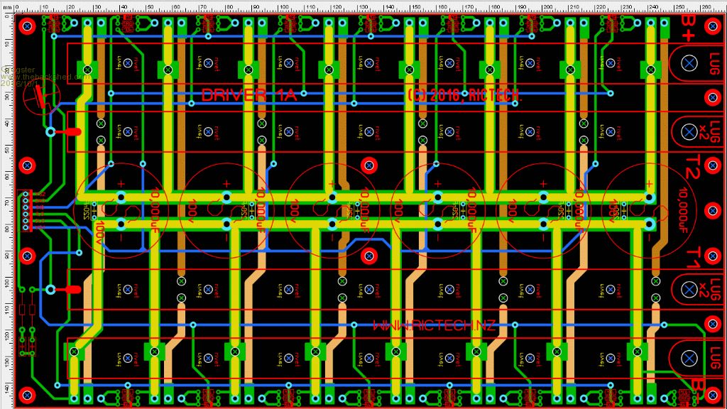 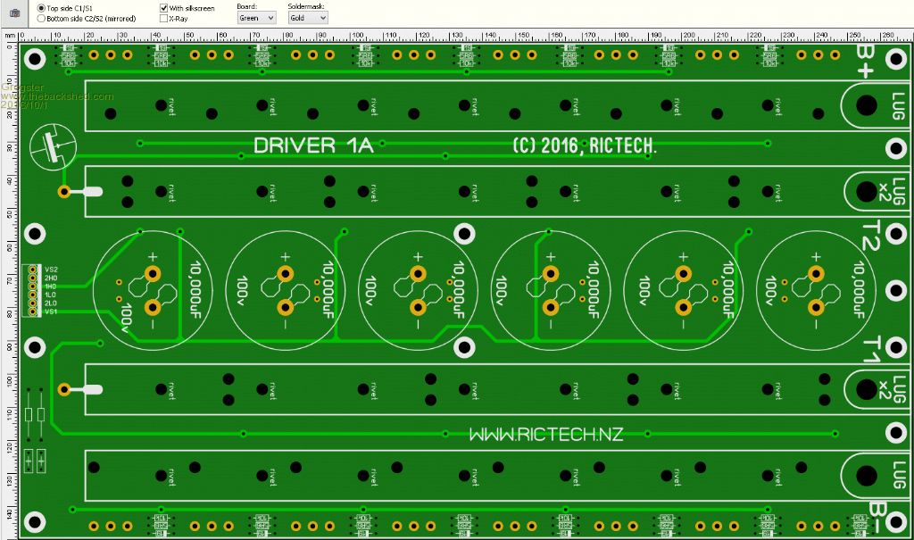 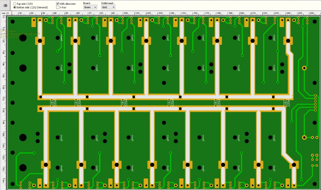 Top coloured image shows tracking on top and bottom.(blue and green) Tan and Brown are the "Inner layers", which are NOT used - I am just using them to show where 3mm solid copper rod lengths will be cut and soldered into place, forming the heavy current paths for the individual FET's. These links are insulated with thick-wall heat-shrink prior to installing them, then the shrunk heat-shrink is stripped back for soldering. Home-made insulated wire.  Being that heat-shrink tubing does not melt, it will work well for when I solder these rods into position, as the rod will get very hot doing that, and normal insulating tubing over the rods would most likely melt and make a mess due to the heat involved. Being that heat-shrink tubing does not melt, it will work well for when I solder these rods into position, as the rod will get very hot doing that, and normal insulating tubing over the rods would most likely melt and make a mess due to the heat involved.The white lines(yellow in the top coloured image) are unsheathed copper rod soldered to the bottom copper, forming the current paths there. The circles with the blue and green X in them in the bus-bar areas, are just plain holes in the board. short lengths of 3mm solid copper rod are passed through these holes, which are drilled right through the copper bus-bars, and soldered to the bar top-side, and to the tracking and 3mm rods on the bottom. The four 15x3 copper bus-bars on the top carry the total load to the toroid. These bars will be insulated with heat-shrink too, and I can just cut away with a knife where I need to. I am winding my primary out of two-in-hand 8GA(about 3.2mm diameter) OFC car-amplifier power cable. I am thinking about making this three-in-hand, but for MY inverter, probably not necessary, as I calculate the primary current to be in the area of 135A or so full load(3500W), and I won't be pushing the inverter that hard anyway. I might just make it three-in-hand though, because the conservative engineer in me is telling me to.  I am calculating the primary current from 3500W / 26v or so that the 8010 is designed too drive, but if I have that wrong and should be calculating for 48v - which is the battery bank voltage - please let me know. In both cases, assuming the lower voltage will ensure the primary is grunty enough either way. I do have some 25mm2(about 7mm diameter copper core) welding cable, but when I measured it, and then calculated how many turns I expect to have to put on the toroid, I am a meter or two short of what I need. The big fat welder cable is harder to wind on then the 97-strand ultra-flexible car-amplifier power cable that I have plenty of here, so...... According to other threads, posts and calculations, I need a primary of about 22-23 turns of that two(or three)-in-hand, so that is what I am working on as of now. Smoke makes things work. When the smoke gets out, it stops! |
||||
oztules Guru Joined: 26/07/2007 Location: AustraliaPosts: 1686 |
3.2mm.... mmmmm not really. Your average current is calculated as input voltage.... 48v-57v. However, current peaks will be very much above this. 3.2mm is only about 1.6x1.6x3.14 or 8mmsq... 2 in hand is only 16mmsq. At 2kw it will get up to 80C or thereabouts with adequate cooling ( open air) So 3 in hand will be better and 4 in hand about right. Or..... I would buy the newer welding cable ... orange with a white inner... cut the orange off, and wind just the inner, that way 35mmsq is easy to control , and fit in there with oodles of room to spare. The board looks very difficult to assemble comparatively, and offers little in the way of improvement over the clockman/pj board. I'm not worried about mv losses in the copper foils of the normal design, but the heat. 2oz seems to stay cool enough, as the dissipation area is very large. The voltage losses across the area is of little real consequence... maybe the caps would argue the point.... but provided you don't use the foil area for signal, it is a non-problem I think. You have concentrated it all in a smaller surface area, even though the cross section is probably greater ( 7mmsq-9mmsq round or square)....and your spreading this over four paths anyway... makes the 2 in hand for 16mmsq seem a bit odd.. as it is about 8 meters in length. Your apparently not looking for much power, yet you have an overly complicated construction... not sure why..... if I were building it..... well.... I'd mess it up, as it looks a brute to build with my skills. You need only carry 70-80 amps or so average at your 3500-4000 watts.... 2 oz foil should ( does) do this easily in the PJ or clockman style.. Will be a work of art when you get it done, and I'm in awe of the engineering... but I think simple would work just as well...for me:) ..........oztules Village idiot...or... just another hack out of his depth |
||||
Grogster Admin Group Joined: 31/12/2012 Location: New ZealandPosts: 9308 |
This board is still a work in progress as I play with ideas and layouts, so this is not what I have ordered or will ultimately produce. 3mm copper rod is cheap. 2-ounce PCB is horribly expensive. It is more then twice the price of a 1-ounce board, and this means the power board is well up into three-digit money for 2-ounce for the size. Still, I will take it under advisement, as you do have a very valid point on the complexity of the build for this one, and that has made me have a bit of a think there. To ME it is no problem, and I am not put off by the complexity - but that is me.  I am wanting to design the power board to be grunty enough to move up to a 6kW or more toroid design in the future. As of right now, this board won't be pushed, but I am putting all the extra bits on the power board now(technically overkill), so that if I wanted to upgrade it's output capability later, the power board could handle it. That was the idea behind the extra stage and bus-bars etc - future proofing it so I don't have to do a new power board later. Even running flat-out on the toroid of choice for now, the power board should not break a sweat. That is why the power board is so juicy for a relatively low final output power. Well, that's the idea, anyway....... EDIT: I will get some more welding cable for the primary then. Smoke makes things work. When the smoke gets out, it stops! |
||||
Madness Guru Joined: 08/10/2011 Location: AustraliaPosts: 2498 |
Hi Grogster, What price are you working on for your PCB's, you can get 10 2OZ boards made in china 180mm X 280 for $215 USD So under $22 a board, I would not have thought that is too expensive. There are only 10 types of people in the world: those who understand binary, and those who don't. |
||||
Grogster Admin Group Joined: 31/12/2012 Location: New ZealandPosts: 9308 |
Yeah, that's about right. But $200+ for a batch of ten boards, only one of which I am likely to use. It's a different story for boards I sell on the website for the MM etc, cos I know I can make the money back, but in this case, as it is just for me and likely to be a one-off, that board is costing me the full $200+, as I am unlikely to make more then one. Perhaps I should considder listing the board on my site though. That WOULD make it more worthwhile, but ONLY if I can move the boards. If you buy a batch of ten boards, to use one of them, 90% of the purchase price is just being wasted on the shelf.  Hmmmmmmm...... Food for thought. Perhaps I WILL look at going back to having that split ground-plane idea from a few images back(2-ounce), and just have my 3mm links to the bus-bars remaining. That would get rid of ALL of those links in white from the bottom of the board. That is an attractive idea, cos it does mean less work to assemble it. Having said that, and with 2-ounce board, that would still be OK for later if I decided to build a bigger toroid, yes? Smoke makes things work. When the smoke gets out, it stops! |
||||