
|

|
Forum Index : Electronics : blown resistor
| Author | Message | ||||
| irishron40 Senior Member Joined: 22/09/2014 Location: IrelandPosts: 251 |
i check that oztules. i just blew an other tip when I shortend the two outputs. thought the lm723 had protection against that from happening. or is it that the tip41c are too sensitive oztules? i am just a beginner , so have loads to learn. i have ordered some tip3055 transistors . maybe those are better btw. is it possible to put on each transistor emitter an LED , so if one transistor would fail I could see that by the led not lightning up appreciate the help. thx ron |
||||
| VK2MCT Senior Member Joined: 30/03/2012 Location: AustraliaPosts: 120 |
I suggest not using a motor as a load until getting the power supply working with light globes. This includes getting the current limiting working. Motors have a large current (amps) starting. Motors also have a thing called back EMF which can cause a power supply to fail (blowing transistors). There are components that can reduce back EMF but get the supply working with globes first. John. |
||||
oztules Guru Joined: 26/07/2007 Location: AustraliaPosts: 1686 |
"i check that oztules. i just blew an other tip when I shortend the two outputs. thought the lm723 had protection against that from happening. or is it that the tip41c are too sensitive oztules? " No, the tip41 will do fine .... if they have protection from excess current or voltage. I fully agree with john.. no motor until you get it working well as a simple resitive load driver. When you can prove the over current protection, then it will all run fine, but you cant do that until you get it running for more than a few nano seconds. Research the data sheet for the driver, and see how the current o/load works, and then see why yours is not. You have voltage control, but no current control at the present from your travails thus far.... If Pete can short it out without destruction, it is not the transistor size that is saving him, it is the current o/load circuit. It may be that your transistors cannot drive enough current through the emitter resistors to generate a control signal before blowing up......... before the current control can kick in. I have not used that circuit myself, different ones of the same kind of thing ..yes, so don't know exactly how the current control works.... but it aint at the moment. ..........oztules Village idiot...or... just another hack out of his depth |
||||
| irishron40 Senior Member Joined: 22/09/2014 Location: IrelandPosts: 251 |
ok thank you both. if current can be controlled and turned down to minimum, would it then be possibe to run a motor for testing purpuses without blowing the transistors? ( just trying to understand) I will test it with a bulb, and see can i control current. I think tho that I read somewhere that minimum the current can be reduced to is about 3 amp. (not 100% sure) So if a light bulb draws 2 amp how then can i check if the current control works? thanks ron |
||||
| VK2MCT Senior Member Joined: 30/03/2012 Location: AustraliaPosts: 120 |
I think that the minimum current limit is around 2.5 amps. Use 2 lamps. Be aware that maximum voltage applied to lamps should be 12volts !!! John. |
||||
| irishron40 Senior Member Joined: 22/09/2014 Location: IrelandPosts: 251 |
i will john.thx if current can be controlled and turned down to minimum, would it then be possibe to run a motor for testing purpuses without blowing the transistors? just wondering about how that works. ron |
||||
| irishron40 Senior Member Joined: 22/09/2014 Location: IrelandPosts: 251 |
ok . i fitted 1 transistor as i am running short. the spec says tip41c can give max of 6 amps. i kept the 1k and 3.3k in place in sted of the 120 and 330 ohm resistors. i set output to 12 volts. I then connected a 12 volt bulb which draws 1.6 amp the moment i connected it the transistor blew again. grrrrrrrrr |
||||
oztules Guru Joined: 26/07/2007 Location: AustraliaPosts: 1686 |
I will have to defer to Pete..... I have no idea how that is happening. It should be simple, but somehow you have made it not so simple as it looks. ......oztules Village idiot...or... just another hack out of his depth |
||||
| irishron40 Senior Member Joined: 22/09/2014 Location: IrelandPosts: 251 |
i know. i am sure problem is on circuitboard. 1) on diagram it shows a line to GND under pin 7. i dont have that one i see, as i thought pin7 is getting ground alleady comming from the bridge rectifier, ( surely that cant be the problem can it? )I do have a neg lead from capacitors and from c10 to neg output terminal 2 I have a thick positive lead connected between the R5 and R6 and my positive output terminal. the positive output comming from R7, C10 & the 500Ohm pot< see attachment) 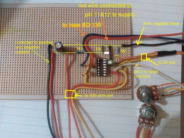
bd139 and tip41c are def connected correctly and so are the large resistors. so I realy feel its somewhere here with a lead connection maybe at the wrong spot that causes the problem |
||||
oztules Guru Joined: 26/07/2007 Location: AustraliaPosts: 1686 |
Pin 4 may not be as high an impedance as I first thought looking at this. 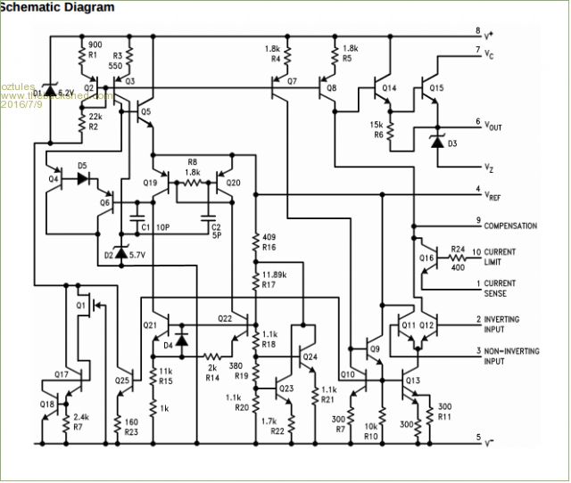
So maybe you will need to go lower impedance again... but maybe still higher than 390r:120r... may be just double it and the power dissipation will drop 4 times. I am at a loss to see how it works in practice. I expected an op amp there, nut it is a sort of op amp, where as pin 2 and 3 is more what I expected internally. The fact that it still worked means that it is fairly high impedance, just not as high as I had thought. I really don't know what to tell you yo do next, as I am not there... all I would try is to run it, and try to very gently load it up ( maybe 100r) and see what changes. When looking for faults of any kind.... change is what I look for... then nut it out to see why it changed for better or worse... it is in this process I usually find the problem. Curious... what is the input voltage? .............oztules Village idiot...or... just another hack out of his depth |
||||
| irishron40 Senior Member Joined: 22/09/2014 Location: IrelandPosts: 251 |
37 volt input/ transformer is able to supply 15 amp everyone else has it working , so it must be something i did wrong. does it look i have the 500 ohm pot wired correctly.? middle pin on pin3 from lm723 left pin on pin 2 from lm723 right pin between output terminal and R7 I have the outputs from the stripboard connected to output terminals. will the output from the large resistors not feed it back in there? or is that not possible also it shows a ground connection. surely that is only for safety and nothing to do with the workings of it? thanks oztules ron |
||||
TassyJim Guru Joined: 07/08/2011 Location: AustraliaPosts: 6101 |
The pin numbers on your circuit are referring to the round can, not the DIP package. 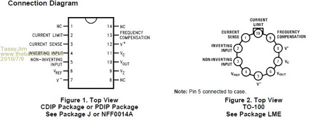
Jim VK7JH MMedit MMBasic Help |
||||
oztules Guru Joined: 26/07/2007 Location: AustraliaPosts: 1686 |
Thank goodness for that Jim... as I could not see how that circuit would work in practice... it made no sense to me at all  .. thanks for that..... I need reading lessons from the looks of it. .. thanks for that..... I need reading lessons from the looks of it.
"37 volt input/ transformer is able to supply 15 amp ".... you realise thats far too much voltage for this thing.. that should rectify out to at least 50 something volts... probably more if you mains are high, which seems normal now days with grid ties all over the place.. you probably have your problem right there.... 25% over voltage on the chip would stuff things up I suspect. If your tranny is a centertapped thing, then full wave rectify using the center tap as gnd or -, and you will have 25v to play with ... albeit at 30 amps. .....oztules Village idiot...or... just another hack out of his depth |
||||
| irishron40 Senior Member Joined: 22/09/2014 Location: IrelandPosts: 251 |
no i have 37 rectified i man oztules. I have the outputs from the stripboard connected to output terminals. will the output from the large resistors not feed it back in there? or is that not possible also it shows a ground connection. surely that is only for safety and nothing to do with the workings of it? ron |
||||
Downwind Guru Joined: 09/09/2009 Location: AustraliaPosts: 2333 |
Ron, For starters draw your circuit on paper as you have constructed it, wire for wire link for link, component for component, etc. Do not look at the schematic i gave, then compare the two drawings. When you quote this wire is connected to that point means nothing to me just confusion. So draw the circuit as you have built it. There is a few solder joints on your board that looks close to bridged tracks so check them. Some of your drill points on tracks to place a break might need checking, that there is not a micro copper fiber remaining causing a bridge between tracks. The problem is a construction error somewhere, albit my crystal ball has its own faults and problems of late (it is Chinese made off ebay) so unable to pin point the problem. one suggestion would be to remake the PCB as there is basically no componets to it. Pete. Sometimes it just works |
||||
| irishron40 Senior Member Joined: 22/09/2014 Location: IrelandPosts: 251 |
Hi Pete I did check every track and solder points with my continued test setting on multimeter. it shows no shorts anywhere. this is the 3th pcb i made, and each on same prob. It seems to be working until I connect any form of a load i just wonder this. I have the outputs from the stripboard connected to output terminals. will the output from the large resistors not feed it back in there? or is that not possible also it shows a ground connection. surely that is only for safety and nothing to do with the workings of it? |
||||
| irishron40 Senior Member Joined: 22/09/2014 Location: IrelandPosts: 251 |
I started drawing as you sugested Pete. Its amazing what you see when you do that 
would this be the culprit?????? on my veroboard you see a red square. it shows that the orange wire going to my 500 ohm pot is between the R7 and C10 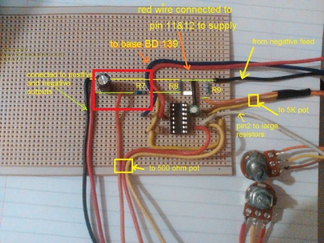
on your drawing it shows that that the R7 is between 500 ohm and C10. 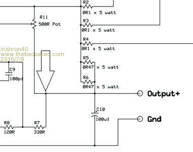
also wondering a bout the Gnd showing. why is this? isnt pin 7 allready getting ground from negative side capasitor? 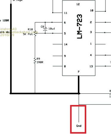
could this be my problem ? thanks ron |
||||
Downwind Guru Joined: 09/09/2009 Location: AustraliaPosts: 2333 |
Ron, You are looking at my diagram as you trace you circuit out, that is not allowed, as you will think you have it correct and follow the same path as you are on. Do a full drawing from your circuit only. Then compare the two. As for the Gnd leg you refering to, it has no other purpose other than to indicate it is a Gnd supply on the schematic, simply i could not find a Gnd symbol when i drew the circuit, so used Gnd. It makes no difference to where a junction in a circuit takes place, as a schematic is only a wiring diagram and not a exact road map of intersections unless indicated. My guess is you have no current control to the circuit and the problem is located in this part of the circuit. I can not see where and only you can. For the fact you have burnt up R7 several times would suggest a problem there perhaps, and also by now would expect the LM 723 chip to be likely damaged by the past problems. Pete. Sometimes it just works |
||||
| irishron40 Senior Member Joined: 22/09/2014 Location: IrelandPosts: 251 |
ok Pete . I drew this from my build. I hope you can see where I am going wrong. I have 37 volt Dc going into board after regulated thanks ron 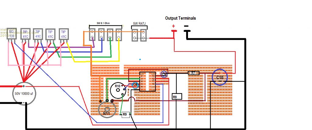
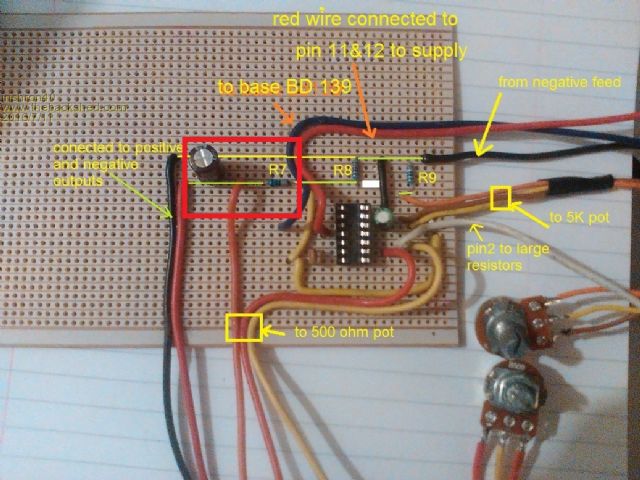
|
||||
| VK2MCT Senior Member Joined: 30/03/2012 Location: AustraliaPosts: 120 |
I'm wanting to check that that there aren't solder bridges between board tracks. So - with the power off and the LM723 removed from its socket and both R10 & R11 (pots) centered ( not at either rotation end), please measure between the IC socket pins and report: IC socket Pin1 & pin 2 = how many ohms Pin 2 & 3 = how many ohms Pin 3 & 4 = etc pin 4 & 5 = etc Pin 5 & 6 = pin 6 &7 = Pin 7 & 8 = Pin 8 & 9 = pin 9 & 10 = pin 10 & 11 = pin 11 & 12 = pin 12 & 13 = pin 13 & 14 = pin 14 & 1 = John. |
||||