
|

|
Forum Index : Electronics : 8 KW Inverter Build
| Author | Message | ||||
Madness Guru Joined: 08/10/2011 Location: AustraliaPosts: 2498 |
Hi Clockman, It is reassuring to here I am not the only one, I actually have that 2uf capacitor connected in the photo. It is the 2 black wires going off to the right, I will find some where to screw it to the case when I get to that stage. Also you will see the 2 N4007 Diodes connected to the output of the transformer sitting up at an angle, I had to drill new holes for them. You can see the transformer I have used which is a PCB type would be a better option in my opinion. That part of the board certainly needs some rearranging, there is space above and below the transformer that could made better use of. After I get this one up and running I plan to do a version with an Arduino which I will use for sensing current, voltage, temps etc. This will then control fans, over temp shut down (or possibly partial shut down first of non essential loads). Other option I am thinking of is data logging and connecting it to my network, this will allow graphing of variables etc which is quite easy to with the Arduino. There are only 10 types of people in the world: those who understand binary, and those who don't. |
||||
| Clockmanfr Guru Joined: 23/10/2015 Location: FrancePosts: 429 |
Originally I made the first OzControl board 6mm longer, then I found out that nowadays the PCB manufacturer prices on size. As you can see in this photo I have lifted the Isolation 220vac to 12vac transformer on to 4mm high spacers for this particular board and that is what I will recommend. The 2uf capacitor is on and firm, but just looks untidy. Some time I will give the board another 6mm in length to be more pleasing to the eye. 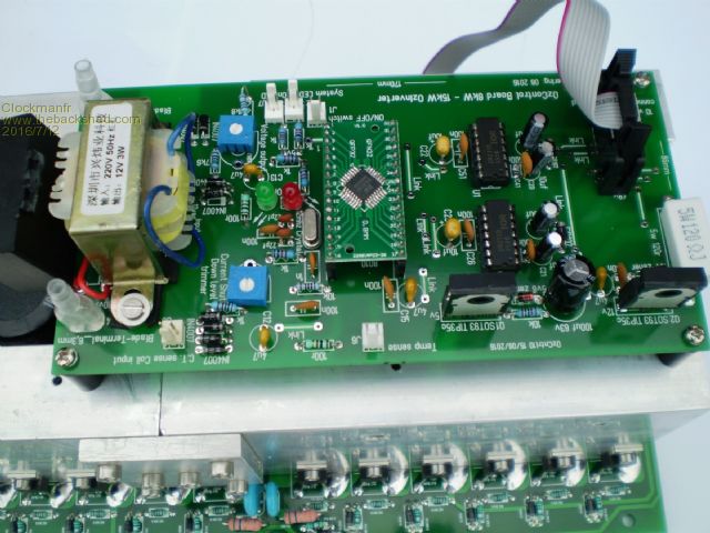
Everything is possible, just give me time. 3 HughP's 3.7m Wind T's (14 years). 5kW PV on 3 Trackers, (10 yrs). 21kW PV AC coupled SH GTI's. OzInverter created Grid. 1300ah 48v. |
||||
Madness Guru Joined: 08/10/2011 Location: AustraliaPosts: 2498 |
Hi Clockman, Where you doing a double sided version also? I will be making a double sided version and including an Arduino and sensors as well. I see you have made some changes to LED and a number of items, looks very good. I still like the PCB mount type transformer though, even if it takes a little more space it is simpler to mount as there are no screws and that frees up space above and below. Gary There are only 10 types of people in the world: those who understand binary, and those who don't. |
||||
Madness Guru Joined: 08/10/2011 Location: AustraliaPosts: 2498 |
Have made a bit more progress after getting PCB etching sorted out. Here is how I have mounted the mosfets so that they will clamp onto the larger Aero Sharp heat sink. The perspex that I have used has a working temperature rating of 80 degrees continuous and up to 120 intermittently. 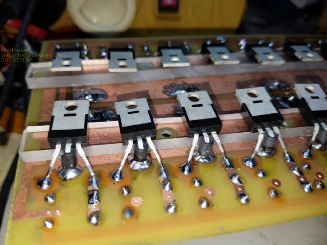
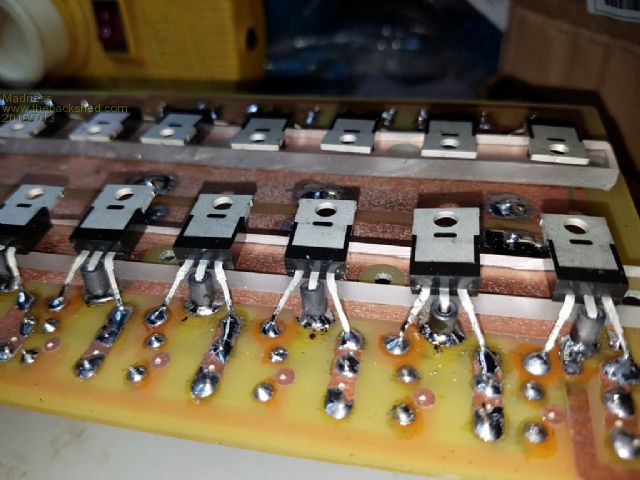
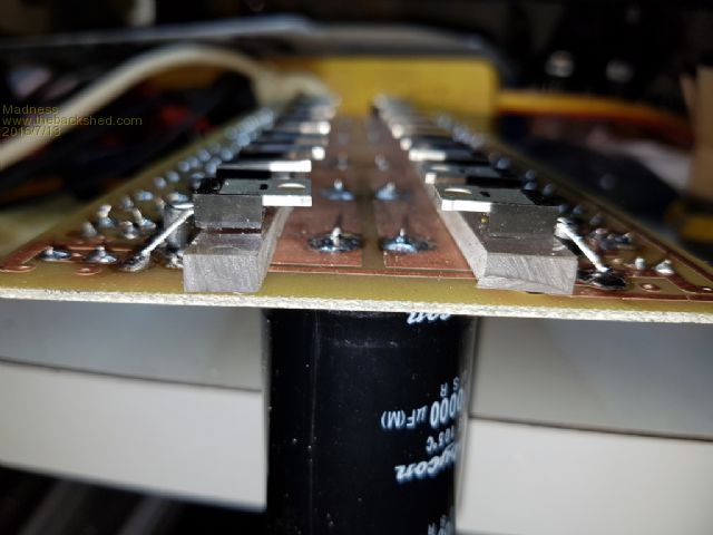
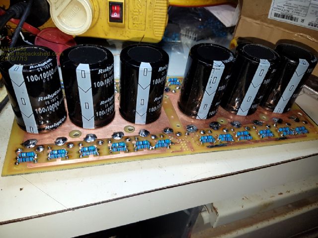
There are only 10 types of people in the world: those who understand binary, and those who don't. |
||||
oztules Guru Joined: 26/07/2007 Location: AustraliaPosts: 1686 |
Mad... here is the 3kw aero with the inspire heat sinked board ( modified clockman board. No fans, and testing showed today that 2.5kw for 1 hour raised the heatsink 18 degrees above ambient, transformer was 30 degrees above ambient. I have set it for 5kw cut off... instant loads far higher. Needs further testing when there is some sun to replace the electrons I waste. ...........oztules Village idiot...or... just another hack out of his depth |
||||
Madness Guru Joined: 08/10/2011 Location: AustraliaPosts: 2498 |
Hi Oz, I have to say that looks very professional, people will think you bought it 
How do think that transformer would compare to mine with 64 & 8 mm square windings? Did you make those labels on the front? A little trick I found when drilling the PCB's, cut a bit of masking tape about 10 X 20 mm, fold it put the middle of the long side on the drill bit a few mm above where it would hit the board so you have a 100 mm square flag. It blows all the dust just far enough away with out making too much mess but makes it very easy to see what your doing. There are only 10 types of people in the world: those who understand binary, and those who don't. |
||||
oztules Guru Joined: 26/07/2007 Location: AustraliaPosts: 1686 |
Yes labels are from A4 label paper, then A4 clear label sheet. It makes a very strong, and chemical resistant surface. The transformer you have made is many times better than the one I built for this one. I only wanted a 2-3kw continuous with no fan, so it is only having to support 10-15 amps so secondary is 6mmsq, and primary only need do 60 amps so 35mmsq. It has massive surge if needed, and would run 4-5kw for 30 mins I guess, still need to test this. Yours is very much superior, and this is only a test bed to try different thermal ideas... like the massive heat sink. Clockmans board is bigger than yours, so yours would be better for this topology, but Clockmans is very solid, and could easily cater for many blow ups without a problem with fiddly tracks... and this one should blow up I expect... that what test beds do I guess. Also, this system we are using is very fast to pull the heat sink and fet board out to repair.. probably 5 mins tops. Like the tape idea.... annoys the hell outta me. blowing away the dust all the time.. I kept the fets very close to the surface without spacing so that the legs are very very short, and only the wider parts are used really.. better current carrying I think, but no room for ferrites on the center leg...... does not seem to bother it. I saw a unit on alibaba that used what looks like a larger egs002 type board, but it also did AC coupling to generators etc.... ie ups operation. I could not find a decent source for the silicone rubber stuff, so used discrete mica, but a strip of thermal silicone would be nice.... probably not as good as mica perhaps but more friendly. If the primary gets too hot... I will do madness thing to it with 2mm enamel wires 
.............oztules Village idiot...or... just another hack out of his depth |
||||
Madness Guru Joined: 08/10/2011 Location: AustraliaPosts: 2498 |
Hi Oz, I had wondered about he legs on the mosfets and their current carry ability. Can beef up the legs by soldering extra wire to them, Removing the ferrites and spacer is an option too if they make no difference. It was a pain in the arse soldering them in like that with the ferrite on there, plated through PCB would have made it much easier. Also I will build a future version with the 247 version of the mosfets. This board is a bit rough, I want to test it before getting some more made. "I saw a unit on alibaba that used what looks like a larger egs002 type board, but it also did AC coupling to generators etc.... ie ups operation." Do you have a link for this, I would be very keen to investigate it. Have been thinking a lot about how to get it to work like a UPS and charge with the generator. That is something the Trace Inverter does so well, generator start and charging is completely automated and seamless. If you watched the switch over with your oscilloscope all you would see is the 50 hz change to match the generator and a more pure Sinewave from the generator. Gary There are only 10 types of people in the world: those who understand binary, and those who don't. |
||||
fillm Guru Joined: 10/02/2007 Location: AustraliaPosts: 730 |
Hey OZ, Looks really good and is getting me more and more wound up and look forward to getting Clockmans boards. How do you think it will handel a mig with instantaneous bursts of 8kW + . Like all the finishing touches and as stated very professional. I have built a 600 x 500 CNC and it makes everything so much better and can do anything from circuit boards to milling 10 ~ 12mm Alu . I will have to do a post on that one day . Anyway all will start falling into place as I am just starting to order all the components and just take it one mistake at a time. PhillM ...Oz Wind Engineering..Wind Turbine Kits 500W - 5000W ~ F&P Dual Kits ~ GOE222Blades- Voltage Control Parts ------- Tower kits |
||||
| yahoo2 Guru Joined: 05/04/2011 Location: AustraliaPosts: 1166 |
oztules testing esg002 it depends on the welder, there are a lot of losses to factor in. I have tested BOC, WIA and UNI-MIG welders in the 270-300 amp range. I figure I need 16 to 20 Kw to run a good bead with the wire speed maxed out and some of the more lossy welders still use 8 kw when they are wound back for the small fiddly jobs. If the welder is not rated at 100% duty cycle it will usually trip its protection circuit in less than 5 minutes (continuous weld), so I have to stop and do something else while it cools down. I think the double bunger transformer should handle that fine. FETS and PCB??? that is Oztules Dept. I'm confused, no wait... maybe I'm not... |
||||
| Clockmanfr Guru Joined: 23/10/2015 Location: FrancePosts: 429 |
Hi Gary, A reply to your questions.... "Where you doing a double sided version also?" In the last picture I posted of the complete Electronics 6-15kW unit PCB for the OzInverter. The OzControl Board on top is the latest design and yes, its a double sided board. Double side boards are only a few cents more each. The fundamental design is unaltered as I also produce the board as a single side simple board for home etch. So the double side board just incorporates the Or/Links/jumpers on to the top surface. The board could end up in any environment so I keep things robust and chunky tracks. I also do the Silk screen as a painting by numbers, lots of info. Which leads me to PCB manufacturers. .... I had been using these folk, http://www.shenzhen2u.com/PCB the boards are okay and the manufacture sticks roughly to the time of delivery they quote. But, but, the latest batch of 6-15kW Power Boards, double sided and double copper thickness has poor silk screen printing. They were struggling on the previous batches, because of the double copper thickness valleys and troughs on the top of the board and small print. Folk get the printed out version of the silk screens so there shouldn't be any issues, they just need to check. Regards the 220vac to 12vac 3w transformer..... I did look at PCB direct mount, but the pin outs are specific to each transformer, and folk around the World can only get what they can get. So my holes are spaced for different sizes and types. I like the open types as I can mount them on lifting up spacers if need be. Also around that area there is no copper, so the mounting screws, 3mm, can be repositioned if need be. "I will be making a double sided version and including an Arduino and sensors as well." I look forward to that.... Everything is possible, just give me time. 3 HughP's 3.7m Wind T's (14 years). 5kW PV on 3 Trackers, (10 yrs). 21kW PV AC coupled SH GTI's. OzInverter created Grid. 1300ah 48v. |
||||
oztules Guru Joined: 26/07/2007 Location: AustraliaPosts: 1686 |
Mad, try this http://www.aliexpress.com/item/Free-shipping-7500AV-W-DC48V-60V-to-AC220V-pure-sine-inverter-board-uninterruptible-power -supply-solar/32690382015.html?spm=2114.10010108.1000023.11.vPWgmV Short circuit and protection.. good question. Initially I tested these things ( the 002 boards) on the big mig. Don't know what the instant pulses were, but average running seemed to be 7kw and less Now IMPORTANT: The 8010 boards have a 4u7 cap on the current shunt, and I have not tried it on the welder since... forgot about that, but I assume it would pass, but be living on the edge, without short protection after maybe 15kw pulses. It would be a good idea to use 1n instead of 4u7, and work your way up to what does it with only occasional drop outs, then a bit more for margin. Now I have Clockmans board, that suits blow ups, I will have to get onto it to get a decent compromise and get the resistor bridge to be range specific so it does not toast the unit from over current conditions. At the moment it has a time lag that MAY be too long for survival of a short as I was thinking of surge support for larger inductive loads... so high cap value....some times I'm not too smart. This gives high surges, with very much lower continuous levels They work so solidly, you sort of forget to retest each newer version against total destruction. I forget to think of others... so will have to test for a happy medium that still gives short protection, as well as very high surge ability. So, Yahoo, yes the tranny will hold it easily... in fact probably bigger than the welders one. The fets will hold it provided you get the cap value and trim pot setting correct. If not correct will probably struggle over 18kw levels without a chance to cut off.... probably more if the truth be known. That welder is big, and blows the 20amp o/l from time to time on the grid switchboard. It now has a 4mh choke in the line so it does not blow fuses, and actually has a nicer weld.... those chokes are in the 3kw aerosharps and inspires... 20 amp units. .......oztules Village idiot...or... just another hack out of his depth |
||||
Madness Guru Joined: 08/10/2011 Location: AustraliaPosts: 2498 |
Hi Oz, Thanks for that link, they don't give away much information, I have asked if they can provide anymore info. Did not see anything there about generator support though. I have been thinking about redesigning my PCB so I could screw the fets to an aluminium block that is bolted to the heat sink and change to 247 package. That way the fets would be as close to the PCB as possible. It would make the PCB stand another 15 mm further away from the heat sink compared to my current configuration. If needed I can fit spacers under the heat sink so it sits further out from the case to allow clearance between the caps and the torroid. A few days ago I raided the bin of the local plastic people (with permission) and got a range off cuts, there is 15 MM thick perspex that would be ideal to fit under the heat sink for this purpose. Gary There are only 10 types of people in the world: those who understand binary, and those who don't. |
||||
Madness Guru Joined: 08/10/2011 Location: AustraliaPosts: 2498 |
I asked for more info about that "Inverter/UPS", they said it is DIY and sent me a picture of a relay.    There are only 10 types of people in the world: those who understand binary, and those who don't. |
||||
oztules Guru Joined: 26/07/2007 Location: AustraliaPosts: 1686 |
I think that the heat sink need not be complicated, as the heat does not transfer as well in that configuration... direct is better I think.... learnt that when I did the linear power supply for 80 amps..... serious losses there. In this case, I found enough room with just the fet case for clearance....hence all the 4mmsq wires involved with it. The board I linked to will do generator support as ac coupling. I did not intend you to think it would auto start the thing as well.... so it will ups, and and a small arduino to auto start the genny is all it would take to do it. ...........oztules Village idiot...or... just another hack out of his depth |
||||
Madness Guru Joined: 08/10/2011 Location: AustraliaPosts: 2498 |
I was looking at 50 x 25 mm aluminium bar bolted to the heat sink with some of that white thermal paste under it, surely that would not have trouble conducting heat? Sorry OZ I had no thought that it would auto start, the link has virtually no information and as I said when I asked the chinese for more they just sent a picture of a relay. Auto start with Arduino is so easy, could even do it via the internet with my mobile phone if I wanted. But I can't see any information there about basic UPS let alone generator support, is there somewhere that you found more information about it? There are only 10 types of people in the world: those who understand binary, and those who don't. |
||||
oztules Guru Joined: 26/07/2007 Location: AustraliaPosts: 1686 |
No... the fact it can ups ( with the extra relay) is all I need to know... that plus the pictures. Generator support is simply an ac source support... same thing... ups. The sync transformer gave it away for me.... it senses the mains/gen freq, syncs.... then shuts relay and off we go..... same as the PJ The torroid will still cause the problems if like the pj they rapidly change frequency back to inverter freq from mains/generator frequency.... if they soft change the freq back to inv freq, it would be fine. ........oztules Village idiot...or... just another hack out of his depth |
||||
Madness Guru Joined: 08/10/2011 Location: AustraliaPosts: 2498 |
Thanks Oz, I will give that Chinese Inverter a miss unless some one else is game enough to try it and proves it works reliably. Once I get a working Inverter I will be trying to sync with an Arduino either with the variable frequency on the EG8010 or directly from the Arduino. My thoughts are that if I have full control with an Arduino it could alter the output wave form to regulate charging. My aim would be emulate how my Trace inverters are able sense current flow both into the batteries and load, this allows it to load the generator up to a preset limit but not go beyond that. Also then it can control battery charge voltage etc. The Trace senses when there is an external AC input and if it is within 3 Hertz and voltage limits it then attempts to sync with it, if this can't happen within a set time it will error and restart the process. If the input is the generator transfer switch (there is a grid one also) it also has a user preset time to allow the generator to warm up. Other functions of this I would to implement too are generator start if Battery V is > X for a set period (5 minutes) Generator will auto start. Auto start would have a quite time set so it won't start in the middle of night unless battery volts drop to a lower set level, then generator starts regardless of time. Separate to Generator control I also will add data logging which will be view-able via IP. This will include temperatures, current flow etc. There are only 10 types of people in the world: those who understand binary, and those who don't. |
||||
| stevebequik Newbie Joined: 20/07/2016 Location: AustraliaPosts: 12 |
Hi Madness. I am getting things organised to build a inverter. Sounds like you have access to a source of caput aero sharp inverters. I am also in Qld(TSV). So wondering if you can supply details of your contact or source me an 3kw directly? Thanks |
||||
oztules Guru Joined: 26/07/2007 Location: AustraliaPosts: 1686 |
Mad, I have been struggling with the short circuit protection... and so far it is patchy, and I don't know why..... sometimes it works, others it does not. I can see some problems in the feedback line, but at this stage have not solved it completely... The big problem is each test kills the mosfets. The original one did seem to be stable, and worked the welder and shorts, but now OI have trouble with the short circuit aspect, it still drives the welder ok at full current. I have trouble shorting the thing as it goes against everything I have tried to do all my life, so did not look seriously at this aspect... I still can't bring myself to do it, so just hook up a big torroid and start it if it can. Will keep trying to solve this but it will take a lot of patience and time. This morning it was running 35amps fine, and I could set the current pot to o/load at different no of 2kw elements, but the actual short was too much... not sure what I have done different from the first unit.. different transformer, and am using the clockman board which could be the problem. As it was supposed to be used, the current was distributed more evenly across the fets, as we are using it, there is more current at some fets at some times.... this may be contributing to the problem. ( no clockman it is not the board, just how I am using it at the moment, may have to go with your heat sinks instead and try that. The PJ fet board did not ever die, this one has died a few times now from shorts, and huge current bursts.... So beware, we may be creating a problem that was not obvious before... don't know just yet. ............oztules Village idiot...or... just another hack out of his depth |
||||