|

|
Forum Index : Windmills : Help with my first windmill
| Author | Message | ||||
oztules Guru Joined: 26/07/2007 Location: AustraliaPosts: 1686 |
Whilst the axial flux looks deceptively simple, it is incredibly difficult to get exactly right so it produces, and does not burn up easily ( it will still burn up though). Too much has to be gotten correct. Ideally, you want lots of field.... ie. magnet placement, gap and type. Ideally you want as thick a wire as is humanly possible. You want complete flux inside the system ( thick steel plates ) You want the skinniest gap you can get...... Now.... when you get all of just ideal.... the thing will not work, as it won't get out of stall.... so you put on stronger profile and longer blades to get it out of stall.. eg bigger GOE222 ... and then..... in the first decent blow... it burns up anyway. It is a very very careful balancing trick to get these deceptively simple alternators to run trouble free... use a known well tested design... and don't ad lib. Anything will work, but for how long is the thing with axial flux windmills. The world is littered with axial flux mills with burnt up stators, and corroded magnets.... they are not a total answer unless your prepared for bulk failures until you learn how to in your environment. A current limiting mill is best for neophytes, as it is forgiving of just about anything... so induction motor conversions or F&P,LG etc... Or if you have a speed limited mill like the old pumpers, then you won't burn up either as they naturally self limit the speed... but very low RPM.... So.. I tend to agree with fillm on this, and a F&P is near idiot proof, and a good little performer, and will not burn up no matter how nasty you get with it. Variable pitch is not simple either, but a very good thing for the axials if you can master the engineering Solar is even better, but you don't get to see the blades turning... and that is satisfying to boot. It is all compromise. ..........oztules Village idiot...or... just another hack out of his depth |
||||
Downwind Guru Joined: 09/09/2009 Location: AustraliaPosts: 2333 |
Hey im a little confused to who is correct here Fillm or Oz, as the diagram Fillm posted at the top of this page has every second coil wound in reverse and then reversed wired so woud have thought it cancelled out, if considered each coil was wound the same way then i think Oz is correct or is Fillm correct ...... Im confused!! Pete. Sometimes it just works |
||||
oztules Guru Joined: 26/07/2007 Location: AustraliaPosts: 1686 |
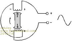
I see your point Downwind... I did not notice the line drawings, so they are in fact flipped and wired reverse..... that cannot work, as it means the + and - are in fact their idea of polarity... which if you look at it cannot function, as minus goes to minus etc.... that cannot work... why? Consider the all North poles and coils, and ignore the south ones for the moment... they are connected in series as they should be to be additive... thats correct. Now consider the south poles and coils, they are seriesed and connected in reverse to the north pole one making complete cancellation... they cannot have it both ways.. ie one theory of 4 connected in series to get added potential, the 4 connected in opposite series and additive in the opposite direction. They either add by +-+-+-+-+-+-+-+- or they dont. They have +--++--++--+--+ and that does not work. ( take a good look at this sequence....it is most amusing as we will see later on) It does mean they meant the + and - to be polarity... I was wrong about that.... mostly because it is completely and totally unbelievable. So I would take note. 1. Sorry ED1 It is not what you stated from a close examination as downwind has pointed out.... you are correct , they are most definitely not. 2. The diagram is wrong if they tried to draw opposite wound coils and reverse wiring at the same time.. and it looks like they tried to represent it as reversed orientation and reverse wiring... so why bother to do either, they may as well just made them all the same, and same orientation....it will cancel out without the confusion. 3. I will go with the FIGURE 9-35, it is sensible, and works as it should, following all the rules. Well spotted downwind.... why would you print a diagram like that I wonder.... unless your trying to show what does not work?? Just to reiterate in it's simplest form so there is no doubt as to how it works: This is from the Navy electronics site: http://www.rfcafe.com/references/electrical/NEETS-Modules/NEETS-Module-05-3-1-3-10.htm Navy Electricity and Electronics Training Series (NEETS) Module 5—Introduction to Generators and Motors Chapter 3: Pages 3-1 through 3-10 SINGLE-PHASE ALTERNATORS A generator that produces a single, continuously alternating voltage is known as a SINGLE-PHASE alternator. All of the alternators that have been discussed so far fit this definition. The stator (armature) windings are connected in series. The individual voltages, therefore, add to produce a single-phase AC voltage. Figure 3-5 shows a basic alternator with its single-phase output voltage. 
Figure 3-5.—Single-phase alternator. We can clearly see it is +-+- it is not +--+ I'm pretty sure the US navy has it nailed by now, but the other folks don't quite get it from the looks of it.... And to add insult to injury, they have two positive outputs... and no negative ... which is very unusual if you actually want it to work usefully, and what you should expect if it is wired +--++--++--++--+.. as they have. I missed that too last time, as I could not have,..... would not have believed that they meant it. ( actually I think this alone would have clinched it that they really are out of their depth.... two positive outputs is pretty terminal really  ) )
.........oztules Village idiot...or... just another hack out of his depth |
||||
fillm Guru Joined: 10/02/2007 Location: AustraliaPosts: 730 |
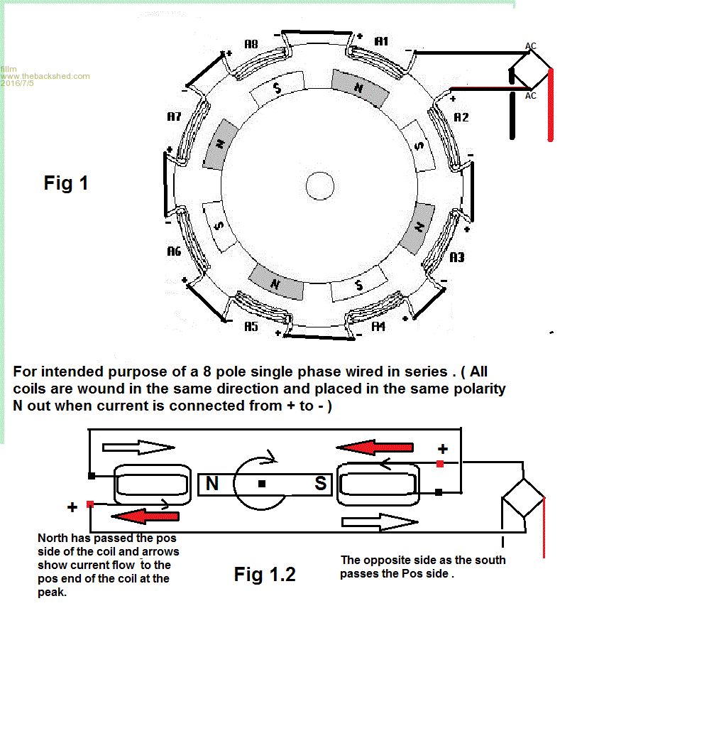
Hey Pete, OZ,ED, now you have me thinking again and I am tying to get room to room heat transfer done from the furnace I just installed. Anyway,I modified the drawing I borrowed that is the heart of the controversy to the Nose / Tail +- start finish.. whatever. At first I was confused but now I know I am confused and if everybody is confused where does it stop . 
I then just put the which way the coils are into ( they are all the same ) see Fig 1 . Then if they are connected +-+-+-......is where it gets cloudy is the fact they are coils and are their own sine wave when a pole passes if that makes sense . I then drew Fig 1.2 and added the current flow as a N and S pass one side of the coil and lone behold I end up with 2 Positive if you want to call them that. If they were connected as shown then as the N&S pass the other side of the coil they become Neg. But wouldn't coils would be classed as no polarity until current passes through?. This then makes my fig 1 wrong and no current will flow as everything cancels, making the original correct. I think where it can become confusing is the way simple diags are depicted as one pig tail winding instead of 2 and in opposite direction. I see the only way this single phase working with the +-+-+- and so on, is if all the magnetic poles are the same. or every alternate winding or coil be wound in the opposite direction. Throwing this one out there and Happy to take the flack !! I keep thinking that I have overlooked something blaring me in the face?????? 
PhillM ...Oz Wind Engineering..Wind Turbine Kits 500W - 5000W ~ F&P Dual Kits ~ GOE222Blades- Voltage Control Parts ------- Tower kits |
||||
oztules Guru Joined: 26/07/2007 Location: AustraliaPosts: 1686 |
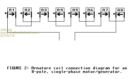
Good to see the source pics... now we know what we are looking at. 1.Pete, this man may have drawn the coils in 2 orientations, but he did not mean to... in fact it is how I suggested in my first critique.. ie his + and - does not refer to polarity of voltage, but to the orientation of the coil... should have used A and B as I suggested first off... less chance of misinterpretation. Luckily he also gave us this diagram explaining his works... the dot is the orientation he calls + in his main diagram. We usually use the dot to represent the start of a winding, and that gives us the orientation. 
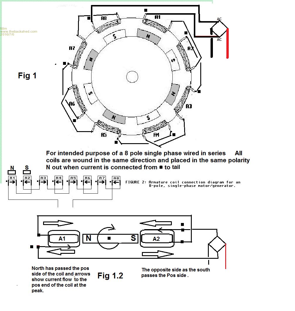
Here he is saying exactly what ED1 and I have said.... reverse the wiring to each second coil if the orientation is the same. Note: the arrows are the current direction under the influence of their respective magnets... this proves that the coils are all in the same orientation. In his second picture, the one you posted, he has done the same thing but, Pete and then I also thought he had changed the coils and the wiring.... we looked too closely, as he says: "Lay your coils out in a row so that their positive lead is on the same side of each coil in the row, and connect them in series so that the negative lead of the first coil connects to the negative lead of the second coil, the positive lead of the second coil connects to the positive lead of the third coil, and so on. The proper connection is simple to show using the diagramming technique presented above. Just draw lines to connect the coil boxes so that the lead nearest the head of one box's arrow connects to the lead nearest the tail of the next box's arrow (figure 2). Physically making this connection relative to the positive leads as drawn on your coil diagram guarantees the alternating current flow directions in the coils do not oppose each other" So there you have it. he says "Lay your coils out in a row so that their positive lead is on the same side of each coil in the row"..... exactly as he has in figure 2 So his + and - simply refer to the orientation, as I suggested early on. That gets rid of the confusion/ambiguity. Next you ask "Then if they are connected +-+-+-......is where it gets cloudy is the fact they are coils and are their own sine wave when a pole passes if that makes sense ." Yes they are their own sine wave, but they are locked into a fixed timing regime mechanically, so that with the proper coil connections +-+-etc their waves are additive... if we were able to move the ,magnet positions ( gap, orientation .. maybe swap a few magnets around etc etc) while running we would change the timing of the wave forms from each coil, and end up with the vector addition of every wire in the system for the total... whatever that may be. So his picture is correct if you do not look at the line drawing of the coil, and just use the orientation of the +- as orientation, NOT voltage per say... better still if he used the dot nomenclature as he did in pic 2 Interestingly he states " OK, I'll be honest, I only built a model single-phase motor/generator because I didn't know what the hell I was doing and screwed up my first attempt at building a model three-phase motor/generator." I was no different at the start. Amazing how much better you learn when you stuff it up Once you find out how/why emf is generated in the wire, it becomes clear as to why it all works as it does. In your fig 1.2... just assume your + is the dot....and not a polarity....it is confusing you.... then it works fine. Now you have a dot not a plus....look carefully at your RED arrows.. forget about the white ones, they will just confuse you as well....so to keep it simple, we will ignore them. In this instance the left hand coil has the red arrow going FROM the coil to the rectifier... output A... at the same time your right hand coil has the red arrow going INTO the coil from the rectifier... so must be the inverse of output A... all good 
The Harvard man has confused you with the + and - instead of A,B or just a dot to represent the orientation. ..............oztules Edit 99.... and yes that means your newer version is incorrect... needs the wiring reversed, or explicitly say the coils are reversed... and perhaps use dots not + and - signs... that was the real problem in both that and your 1.2pic. if you get rid of the + and make the red box clear ( to be a dot thing ) and no black box, it will suddenly seme simpler... oh and the clear arrows OR the red arrows. Ambiguity is a real killer in these things, goes from bad to worse quickly... then your mind starts to swim.....eyes glaze over etc etc... mine do anyway. Village idiot...or... just another hack out of his depth |
||||
fillm Guru Joined: 10/02/2007 Location: AustraliaPosts: 730 |
Hopefully this is now correct ? I only went with the + - thing as that is where it kind of started or should it be Nose Tail ?  PhillM ...Oz Wind Engineering..Wind Turbine Kits 500W - 5000W ~ F&P Dual Kits ~ GOE222Blades- Voltage Control Parts ------- Tower kits |
||||
oztules Guru Joined: 26/07/2007 Location: AustraliaPosts: 1686 |
We all learnt something... like we always do. ..........oztules Village idiot...or... just another hack out of his depth |
||||
Downwind Guru Joined: 09/09/2009 Location: AustraliaPosts: 2333 |
To be honest i did know the answer to the confusion question, it was just the diagram information provided in the argument discussed was confusing, which to somewhat caused greater confusion to the good information you guys gave. So i planted a seed of thought to let you guys put it straight for others to follow. Pete. Sometimes it just works |
||||
| kitestrings Senior Member Joined: 23/04/2014 Location: United StatesPosts: 102 |
I regret I missed this topic earlier somehow, but very much enjoyed the discussion. I'll have to re-read and ponder some portions. I've never built a single phase turbine, but my 11-yo and I just put together a small alternator for his science class that - with a little trial and error - works quite well. It is pretty much a mirror of the 4-pole (Figure 9-35) that Oz posted. It was all from odds and ends kicking about my shop, but briefly, I took the teeth off an old saw blade. This was the magnet rotor. I had a bunch of solenoid (valve) coils that we used for the stator coils, and with two pair of magnets and a swivel crank had something that would light up a small (~1.5V) LED lamp. What I did to simplify the wiring was to suggest that he flip over every other coil. So, I think, we are getting the A-B series relationship without crossing the wires where they poke out of the potting of the coils. Does this make sense in the context of your discussions, or am I missing something obvious. I don't mind being confused. I just don't want to contribute to his... Best, ~ks |
||||
| electrondady1 Senior Member Joined: 12/02/2009 Location: CanadaPosts: 208 |
i cast the stator with coil wire ends sticking out of the resin, then i wire the coils up using a volt meter while spinning the mag rotor. |
||||
| kitestrings Senior Member Joined: 23/04/2014 Location: United StatesPosts: 102 |
Yes, I've never liked having terminations buried in the stator, especially the center tap of a wye configuration. It seems akin to putting a junction box in wall and assuming you'll remember it is there (or you won't ever need to get to it). My appologies up-front, on a slight divergence... While I agree to a point Oz, I hope not to have to concede the latter part. We're certainly a long way from proving longevity - our axial has seen only about two years - but after years following fieldlines, Hughs, anotherpower, backshed I'd say a large number of failures are direct-ties where we're simply too ambitious with things. We so want to squeak out all the available power that rather than maybe have a calm (marginally stalled, but safe turbine) we shoot for an unsustainable power curve (or line really) particularly in the mid to upper rpms. I think there have been examples of better results with axial's using some method of load matching either with a programmed power curve (e.g. Midnite Classic), and/or diversion loading. Hugh's, the Dan's, numerous OP contributors certainly have had some robust turbines. Salt air can be a complicating factor for sure. Fortunately we don't have that where we live. Regards, ~ks |
||||
| weaver Newbie Joined: 21/06/2016 Location: United StatesPosts: 7 |
Wow I haven't checked back to this for awhile and wow. Thanks for all the diagrams,they really helped explain a lot. I've moved on from this one and hopefully in the future will get some time to build a larger one that has a decent power output. |
||||