
|

|
Forum Index : Electronics : GP’s inverter build
| Author | Message | ||||
| gpalterpower Senior Member Joined: 19/07/2009 Location: AustraliaPosts: 175 |
Just somewhat of an update of the project. It was sitting at home for a while and nothing was getting done,so I decided to take it to work. Least that way I would see it on my bench every day and that would prompt me to do something in my lunch break. So the first step was to completed the choke 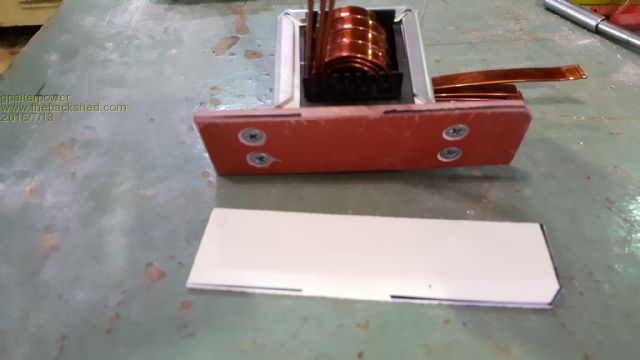
With the countersunk screws coming up from the base I glued on more insulation to keep it totally insulated from the frame where it was going to mount 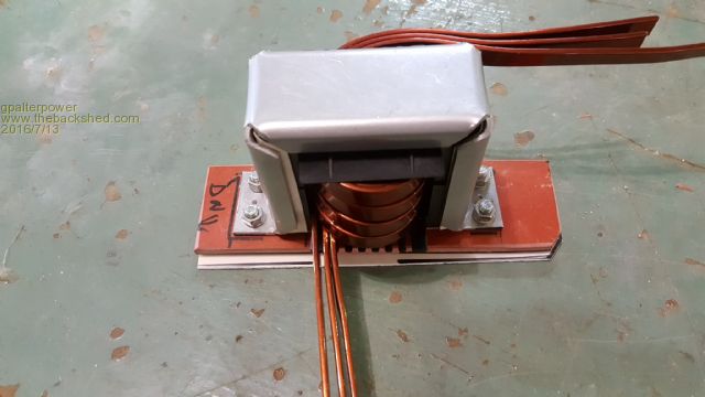
After bareing back the ends of the 3 layers of 8 x 3 enamelled copper, I formed a wedge and drove it into 2 battery lugs so it would accommodate the copper. It was a snug fit and with a little heat applied, the solder took nicely 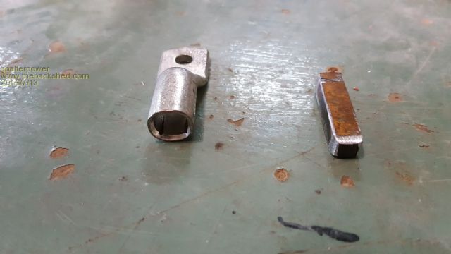
And the finished product 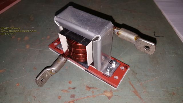
Next was to mount it in the Inspire box 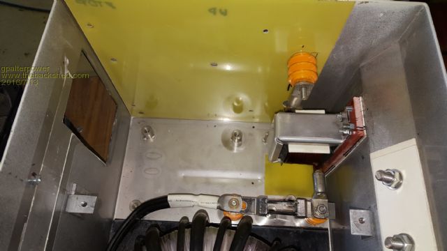
I was able to use some of the existing insulators and holes to mount the choke and the shunt. This made sure that the choke was secure and stable and that no movement was possible. 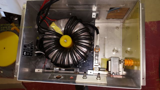
More pics soon if it aint broke dont fix it!! |
||||
Madness Guru Joined: 08/10/2011 Location: AustraliaPosts: 2498 |
I was trying to get that type of copper strip for my inverter build but gave up after a few dead ends, can I ask where you where able to get it. Only option I found was to buy a 60 KG spool of it. There are only 10 types of people in the world: those who understand binary, and those who don't. |
||||
| gpalterpower Senior Member Joined: 19/07/2009 Location: AustraliaPosts: 175 |
Hi Madness, I just went to my local rewinding shop in town. He had all sorts of round sizes but only a few in rectangular shape. Its actually 8 x 2. Not 8 x 3 as I mentioned in the post. 3 layers gave me 48sq mm. Close enough for me to 50mm. if it aint broke dont fix it!! |
||||
| yahoo2 Guru Joined: 05/04/2011 Location: AustraliaPosts: 1166 |
You guys have got that choke nailed! I am liking the photos. I'm confused, no wait... maybe I'm not... |
||||
| gpalterpower Senior Member Joined: 19/07/2009 Location: AustraliaPosts: 175 |
Yahoo. It took about 4 attempts to get it right. The first was wound around a hardwood block I machined . It failed because the ends were too square and didnt allow the wire to form properly for the next turn. A change of strategy and I made the next from 25 mm RHS with 2 tube halves on each side. This time it was overkill as it was too loose. Some where in the middle had to work so I cutting down on the tube end was the answer. Persistance does pay! 
Marcus if it aint broke dont fix it!! |
||||
| gpalterpower Senior Member Joined: 19/07/2009 Location: AustraliaPosts: 175 |
Well I finally got some time to do a but more to my inverter over the last month. Been a slow process but then Im not in in any great hurry to get it completed. In saying that I don't want to to drag on for too long but I'm happy to say its nearing completion. The big test being when I hook it up. Some pics for the update. First one is of the air intake thru a gauze mesh. I have left provision for a filtration pad to be fitted later if need be. See how it goes if it is getting clogged up with dust. view taken from top of box 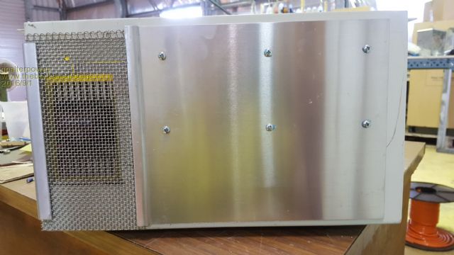
Here is the layout of the main board choke and the new positioning of the shunt. Its getting a little congested in there!! 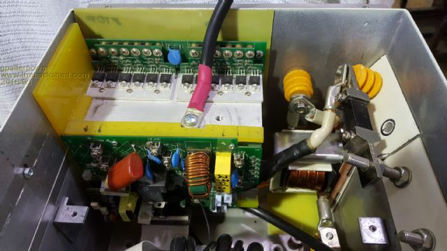
Plan view of the main components 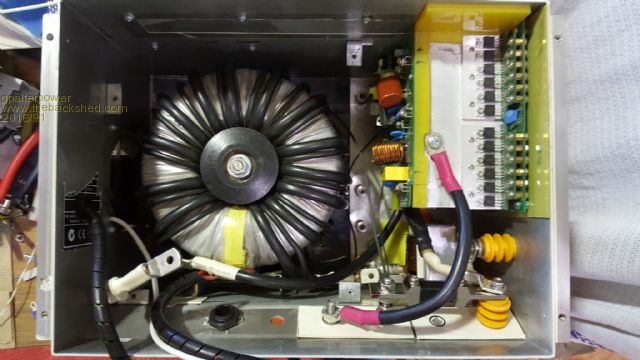
I decided to add a power outlet to the end of the box. Just one of those things that could be handy for testing and usage later. 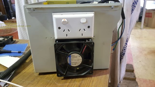
I'm not too sure of the pinouts of the main board or how to get the thing fired up, so I added a wire to each and every of the 20 pins. I was originally going to use some computer ribbon cable( which you may see in the second pic), which fitted neatly into the 20 pins but the wiring was way too small and fiddly to work with. Any help on getting this baby going would be appreciated 
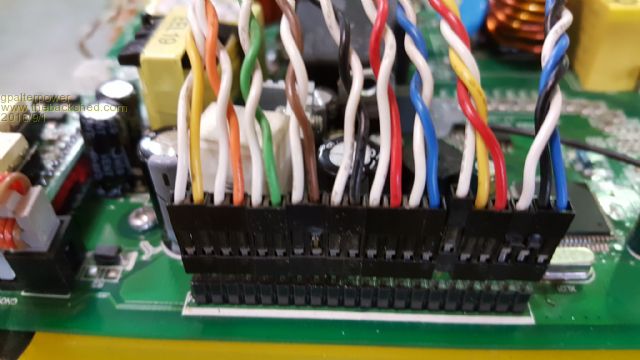
A bit more detail of the main board, choke, shunt and main connections 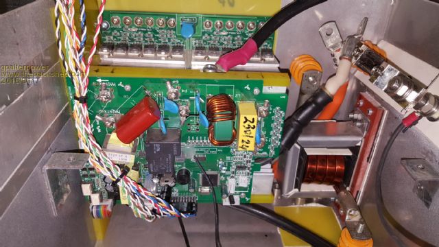
How the front of the box will look with temp controller, V/A/W display , on off switch and the circuit breakers 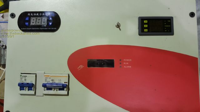
The toroid is covered with the original metal dividing piece but slightly cut down to size to accommodate and mount the circuit breakers and connecting strip 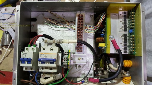
And finally the front cover which I will hinge to the main box later 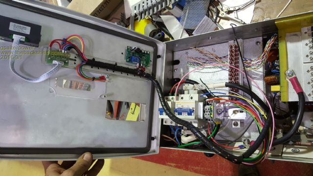
if it aint broke dont fix it!! |
||||
oztules Guru Joined: 26/07/2007 Location: AustraliaPosts: 1686 |
I think your cooling will be a huge problem here. You really only need 2 pins of the twenty in order to use it happily. ( 11 and 13 ) Here are the pinouts as I sent to Gizmo in his project. 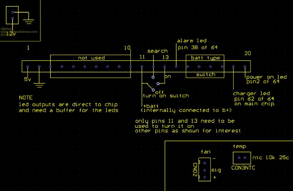
You really need to have air going through the fins, the tranny will look after itself if there is air circulating in there from the fins being actively cooled.... look at Gizmo's gizmo's layout There is a lot of good work gone in to that, but I think the heat will compromise your performance very severely. ..........oztules Village idiot...or... just another hack out of his depth |
||||
| gpalterpower Senior Member Joined: 19/07/2009 Location: AustraliaPosts: 175 |
Thanks Oz for the pinout info. Do I also need B+ to pin 11 as in the diagram or just 11 and 13 joined together. Hopefully I'll have it up and running shortly. The external fan firstly draws ALL air thru the gauze on top and directly over and thru the fins, then lastly over the toroid before exiting. I believe it should work, but we'll have to wait to find out for sure. Marcus if it aint broke dont fix it!! |
||||
oztules Guru Joined: 26/07/2007 Location: AustraliaPosts: 1686 |
I see, thats much better.... although there is a huge difference in blowing and sucking.. blowing is good, sucking is very much less good..... however, thats better than I had figured by a long way, looked like there was no cooling at all in the fins. Velocity of the air across the fin is the key, thats why active blow is generally much better. Pin 11 has voltage from the control card, so no, it does not need anything but connecting to 13. ( the B+ comes to it from the 10 pin connector, through a diode, and cap to 11.) Testing will tell us all... it always does 
Have you got the three pin fan organised as per diagram above? Without a three pin fan, it will stop early on..... ie... once it decides to turn on the fan, it must see the tacho signals or it stops. You may need a zener across the sense resistor to stop over voltage tantrums.. depends on how you charge your battery. best with it. ...........oztules Village idiot...or... just another hack out of his depth |
||||
| Tinker Guru Joined: 07/11/2007 Location: AustraliaPosts: 1904 |
Neat work Marcus. My first inverter is also stuck inside the original Aerosharp enclosure, it looks as tight as yours turned out. I used 4 x 80mm fans, 2 blowing and 2 sucking and they run far more than I anticipated. A good reason to build a bigger inverter  . .
A question, where did you get those yellow ribbed insulated standoffs from? They look useful. Klaus |
||||
| gpalterpower Senior Member Joined: 19/07/2009 Location: AustraliaPosts: 175 |
Thanks Oz , by the sounds of it I may need an extra fan or 2. I could fit 2 80 x 80 fans in the opening nicely. Is it ok to wire them in parallel ? Would it be able to drive the 2 fans? or....better to go for one 120mm fan? Where about does the zener go and what value do I need? Klauss , The yellow stand offs came with the inspire before I pulled it apart. Too good to throw away. I kept them as I was sure I would have a use for them. Marcus if it aint broke dont fix it!! |
||||
| gpalterpower Senior Member Joined: 19/07/2009 Location: AustraliaPosts: 175 |
Oz, Will these ones do? http://www.ebay.com.au/itm/FSY81S24M-80mm-x-15mm-3Pin-DC-24V-3000RPM-Cooling-Fan-for-PC-Computer-Case-/191706109043?hash =item2ca2931473:g:LUwAAOSw5dNWrqqv Marcus if it aint broke dont fix it!! |
||||
oztules Guru Joined: 26/07/2007 Location: AustraliaPosts: 1686 |
Well it is impossible to know from here...... a lot of them have three wires, but they are either not even connected at one end of the third, or just tied in to the B+ of the fan. If you have got clockmans book, then it tells you how to deal with that, if not, then look through my scribbles, and it is there too..... not sure where anymore. 1. I would not consider anything less than 120mm as a decent solution. They can pump air quietly and easliy, 80 and 50 have to work hard to get any where near the same....noisy and early death comparatively..... I buy beecroft 120mm fans full ball race and only $100 per 20 units ebay sydney.. they need conversion and I discuss this somewhere here or another power or other power. 2. Any fan can be converted, as pulses are sent to the coils. You need to identify where there is a pulsing output, put a resistor in series with that, and that can be your third wire tacho signal. 3. The third wire is as the diagram I left.... the commercial ones will probably be the wrong sequence, so you may have to switch some wires around..... also the 3 pin plug will probably be wrong, and need shaping/grinding/swearing to get it to work. I ran a clockman power board today with the cut up heatsinks from the aerosharp Stabilised at 30.5C running 4kw ambient temp 21c in the shed. This is with the 8010 chip.... seems to run very cool really, the PJ sitting next to it was running at 38c but doing only 3kw... fan drifting in and out.... both impressive. I do think the PJ runs hotter though.... waiting to hear from tinker with his two. If you put a single 120mm fan direct at the fins, it will solve the heat problem for anywhere under 4kw cont I expect. The board will run 1 fan easily ( 120mm) and probably two if it has to. I find using your own fan controller is best for both it and you. See if you need the zener first..... you will know as it will stop working when your batteries are nearly 90-100%. If it does I use 5v6 zener... and it too is in the scribbles somewhere. It lays across the resistor near the main chip with "cut if low" printed next to it... cathode towards the chip. ..............oztules Village idiot...or... just another hack out of his depth |
||||
| Clockmanfr Guru Joined: 23/10/2015 Location: FrancePosts: 429 |
Bottom of the page...... my PJ's fan fix and solutions. http://www.fieldlines.com/index.php/topic,148827.27.html The modified fan never really comes on, its a safety fan that the PJ control board requires when the boards get warm, without it the PJ stuff shuts down. In the original PJ board the PJ fan would come on at about 45c. I use the Double OzCooling circuit 2 fans, push pull, 2 temp probes, for the open toroid, and 2 fans, push pull, 2 temp probes, for the boards. Everything is possible, just give me time. 3 HughP's 3.7m Wind T's (14 years). 5kW PV on 3 Trackers, (10 yrs). 21kW PV AC coupled SH GTI's. OzInverter created Grid. 1300ah 48v. |
||||
| gpalterpower Senior Member Joined: 19/07/2009 Location: AustraliaPosts: 175 |
Thanks Oz and Clockman, I can see by the pics how some of those 3 wire fans are just a joke. And the plugs too...no way they are going to fit! So its going to be a gamble if I purchase them from Ebay. Since I already have my 120mm fan mounted I am going for the mod first. seems the easy way out. If that fails then the Beecroft fan will be my saviour. I do remember reading something about the PJ needing the 3 were fan for it to work properly going way back, but that idea must of been shelved in my brain and I continued down the path of having a programmable separate temp controller which you can see on the front lid. In hindsight to all of this, would it be possible if I just used my fan and controller and made sure that the heat sinks never get to that pre determined PJ temp setting. That way if it doesn't get hot then it wont shut down Thanks for you help in this guys. Ill keep you posted. Marcus if it aint broke dont fix it!! |
||||
oztules Guru Joined: 26/07/2007 Location: AustraliaPosts: 1686 |
"In hindsight to all of this, would it be possible if I just used my fan and controller and made sure that the heat sinks never get to that pre determined PJ temp setting. That way if it doesn't get hot then it wont shut down " ......yes or you could program an external controller to shut down in case of over temp, and not use the temp sense for the pj... fixed resistor will take it's place.... but you must be sure that you can shut it down if the temp gets uncomfortable, as the pj cant do that then. The beecroft still needs to be made into a 3 wire thing, and it has no plugs either.... but it does have proper bearings. ......oztules Village idiot...or... just another hack out of his depth |
||||
| gpalterpower Senior Member Joined: 19/07/2009 Location: AustraliaPosts: 175 |
Well I finally finished the inverter and took it home. Hooked it up to a battery bank and hey presto.......the fan worked. Yay! This was something that I was really concerned about, but it drew a LOT of air in and thru the main board, so in that department I was happy. I then plugged in a small load, a fluro work lamp. Turned on the inverter switch and stepped back a little. The lamp came on and then the inverter was groaning somewhat so I shut it down. Another try this time watching the ammeter. After a few seconds start up, the ammeter steadily climbed to about 90A DC. Turned it off again and opened the front door and had a look to see if there was anything out of the ordinary.. All looks ok. Power back on but inverter off there are 2 green leds that are glowing on the pos heat sink side. 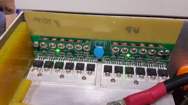
In this mode it was drawing about .3 of an amp. showing .15 but flickers to .5 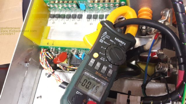
Any help or comments welcome to get this up and running. Marcus if it aint broke dont fix it!! |
||||
| Tinker Guru Joined: 07/11/2007 Location: AustraliaPosts: 1904 |
Marcus, a fluoro lamp might not be an ideal testing load. Try an old fashioned incadescent lamp if you have one or a small kettle or similar resistive load. If it still draws more current than expected then go fault finding. Klaus |
||||
oztules Guru Joined: 26/07/2007 Location: AustraliaPosts: 1686 |
Tinker is technically correct, although in real life that inverter will not give a hoot.. So thats not it. I am wondering if and how you are supplying the control card with the 240v that it monitors, and also the current sense. I cannot see any wire going to the terminals on the control card in that picture. This might explain why it just went gently ballistic... trying to find the 240v, and kept driving the fets to find it perhaps..... ie without a control voltage, it will wind up the pulse width to try to find the AC signal. pics of the control card will help. but it looks that kind of problem, or a short on the output... but that would become obvious, as 90 amps is near 5kw output... you'd notice something. .....oztules Village idiot...or... just another hack out of his depth |
||||
| gpalterpower Senior Member Joined: 19/07/2009 Location: AustraliaPosts: 175 |
Well I tried it again with a heavier load, but had the same outcome. Even with no load it's the same. So with the lid off, I quickly checked the primary and the second when running for obvious signs and thankfully no magic smoke visible. So, I'm thinking that I've missed something or done something wrong. Hopefully Oz you've hit the nail on the head and could be an easy fix!. I only have pins 11 and 13 connected at the on/off switch to make it run. No other wiring is going to the control card except the ribbon cable that they come with. So what wiring is required to hook up to what terminals ? I can see several terminals there that are marked! Should of realised they were for something. Duh! 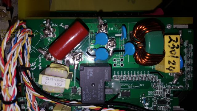
if it aint broke dont fix it!! |
||||