
|

|
Forum Index : Electronics : building an Inverter from scratch
| Author | Message | ||||
| Tinker Guru Joined: 07/11/2007 Location: AustraliaPosts: 1904 |
OK, now I had some progress with this project its time to show what I meant by my comments above. The plan was to use simple single side 1oz PCB, something I can easily lay out and etch at home. Of course, a 1oz thickness track will not do for the heavy currents of an inverter. The simple way to overcome this is to screw on 'tracks' to the PCB's component side. The 'tracks' are made from tinned 1.5mm x 25mm copper strip. I had the strips cut by a local company with a big guillotine from a section of copper sheet I happen to have. I should think that the 37.5 sq mm 'tracks' are more than a match to a double sided 4oz PCB board. Step one was to make the PCB's 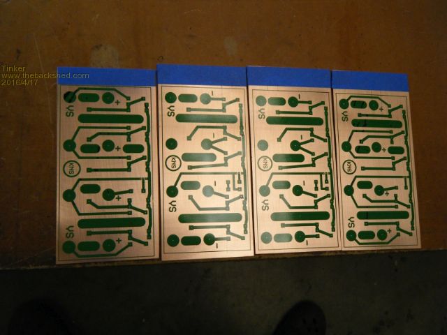
There are 4 boards, 2 identical ones for the positive side and two other identical ones for the negative side. This is what I got after etching & drilling them: 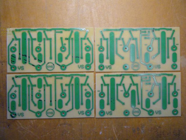
The copper strips were tinned with an industrial size gas soldering iron which easily did the job at its lowest gas flow. 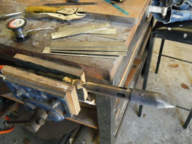
The mosfets legs required to be bent in a certain way, on the left is the one going to the positive rail, on the right the one to the negative rail. Note that the gate is the only leg that goes through the PCB and connects at the copper side of it. 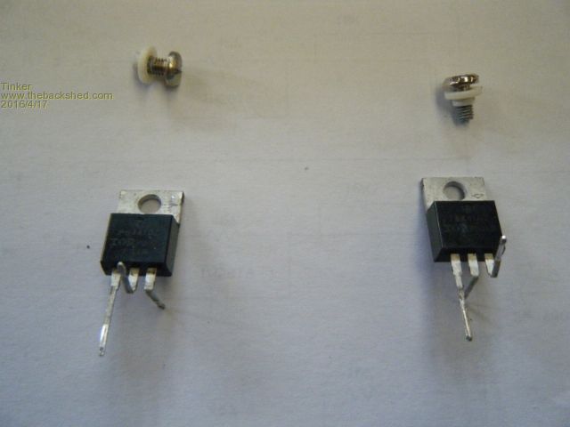
The 4 boards assembled to the 'track' strips, shown are the front and back sides. Note that some components are still missing. 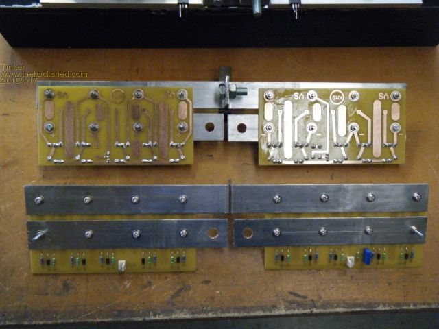
A couple more shots of the lot mocked up. Only 4 of the 20 mosfets are shown, I am waiting for a shipment of 50 of them so I can select 20 with a similar on resistance. 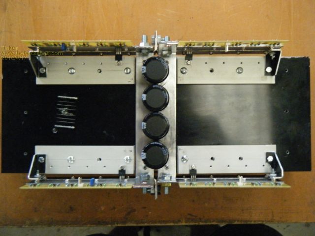
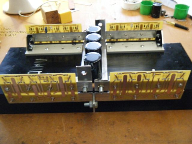
This design is quite flexible, it could easily adapted for more or less mosfet chips. Also the positive & negative connection could be located on one side only or swapped over. There is ample room on one side of the capacitors to mount the little mother board I'm planning to make for the ESG002 driver board, plus its power source & fan control. On the other side of the caps a 230V AC board will house the voltage adj. components, the current sense and the 2uF capacitor plus any other interference suppressor I might need. I do have a smaller toroid (out of a junked 1200W Latronics PVE inverter) that I can use to test it all out, once the lot is completely assembled. Then I have the task of stripping & rewinding 2 x 3KW AeroSharp toroids to make a double stack transformer. Can't wait to get stuck into that  but it might take some time.... but it might take some time....
Klaus |
||||
oztules Guru Joined: 26/07/2007 Location: AustraliaPosts: 1686 |
There are some good ideas in there Tinker.... and some good engineering too. I would condense the distance between the two board systems so the heat sink could be sunk back into the box as and where it was originally... then the whole box will be essentially empty... which is what I was aiming for with my flat design. The ideas are certainly sound though..... may have to copy some of the easy to build parts.... although I think I'm all inverted up for now.... Start the exercise regime now for the transformer mods.... you will find muscles you didn't know about. ....oztules ps 50 fets turned up friday... all came in between 6-7mo Village idiot...or... just another hack out of his depth |
||||
| Tinker Guru Joined: 07/11/2007 Location: AustraliaPosts: 1904 |
Thanks oztules. Yes, there would be other ways to arrange the boards but one has to start somewhere  . I have planned to put legs on the heatsink and mount it vertically inside a suitable box. A single fan on top should suffice. . I have planned to put legs on the heatsink and mount it vertically inside a suitable box. A single fan on top should suffice.
The problem with a flat arrangement is where to put those large capacitors, they need a heavy power track too. Anyway, I have a question for you: That EGS002 inverter driver board arrived today and I duly modified it as you suggested. I got the LM393 off easily by cutting an old chisel type soldering iron tip short so its tip was wide enough to bridge 4 pins of that IC. Wedging a small flat blade jeweler's screw driver under the IC it was simple to heat the pins at one side and lever it off, then do the other side. I put in that link from pin 1 to 4. Looking at the other link (pins 7 to 8) I noticed the resistor (R27) that was connected to pin 7 is not fitted on my board. Pin 7 connects to nowhere else so I see no point to connect nothing on pin 7 to +5V (pin8). Your thoughts on that are much appreciated. 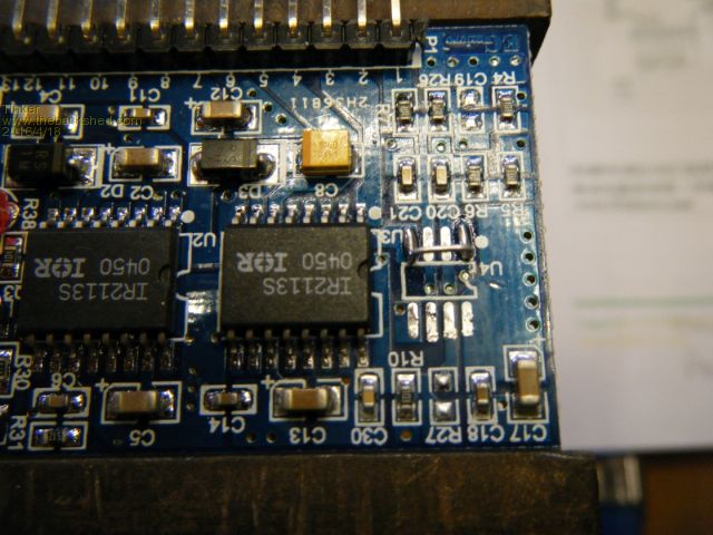
Lastly, in a previous reply you mentioned a second method to turn the driver board on/off (init?), where was that pin located? I don't seem to find it or perhaps I misunderstood your reply. Klaus |
||||
oztules Guru Joined: 26/07/2007 Location: AustraliaPosts: 1686 |
Well that beats all.... never mind. ok, if the r27 is not there, then you can see from the diagram, that there is a 10k resistor to 5v line anyway ( and cap to ground).... this was to turn the 8010 off because of o/load as well..... on mine, it caused blow ups. So I joined it to 5v direct so that it could not do it again... they must have found this out by the time you bought yours ( bought mine a long time ago... and forgot about it..) But lo and behold....... Now the R27 point (8010 side) can be your new on/off switch. Ground it, and you will be off, float it ( or better still connect to 5v) and it will turn on. You only need to get pin 6 to be high or low... and it goes to R27 anyway, and the 10k may be enough anyway... so very easy them. So that answers both questions..... And the caps could run down the center instead of across it... then it will all be inside the width of the heat sink, and the sink can be outside the box, and workings on the inside.... same as original ( but with bigger hole of course).... just my take on it. I like your tidy engineering... wish I had that discipline. ..............oztules Village idiot...or... just another hack out of his depth |
||||
| Tinker Guru Joined: 07/11/2007 Location: AustraliaPosts: 1904 |
Thanks oztules, that sounds indeed a simple way to turn the driver on or off. I'll let you know how it went, I am still waiting for the mosfets & capacitors. Klaus |
||||
oztules Guru Joined: 26/07/2007 Location: AustraliaPosts: 1686 |
50 fets turned up yesterday, and tested out at all around the 5-6 mo... happy camper three times from these folks... starting to make up for the duds previously. Tinker the newer boards I ordered in, don't have the r27 either, although the 7-8 link was easier than the 1-4 jump..... could have been the other way around.... However, I guess we could just jump C19... which is easier... I like.... don't know why I didn't do that in the first place.... ...........oztules Village idiot...or... just another hack out of his depth |
||||
| Tinker Guru Joined: 07/11/2007 Location: AustraliaPosts: 1904 |
Change of plan, oztules suggestion above to have the heat sink outside of the box makes a lot of sense, so much so that I just could not get this idea out of my head and had to do something about it... Anyway, here is what I came up with: 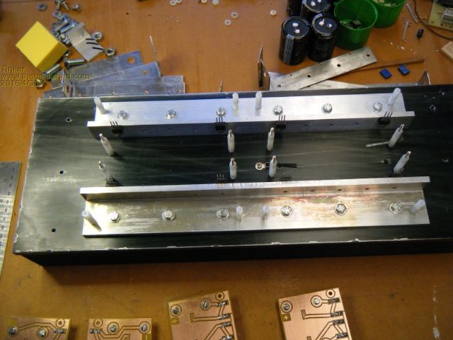
The sub heat sinks are 40 x 40 x 6mm alu angle, cut down to 40 x 25mm. Different PCB's for this idea: 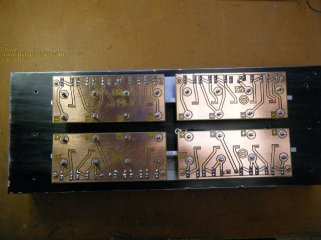
Now with the copper strips added: 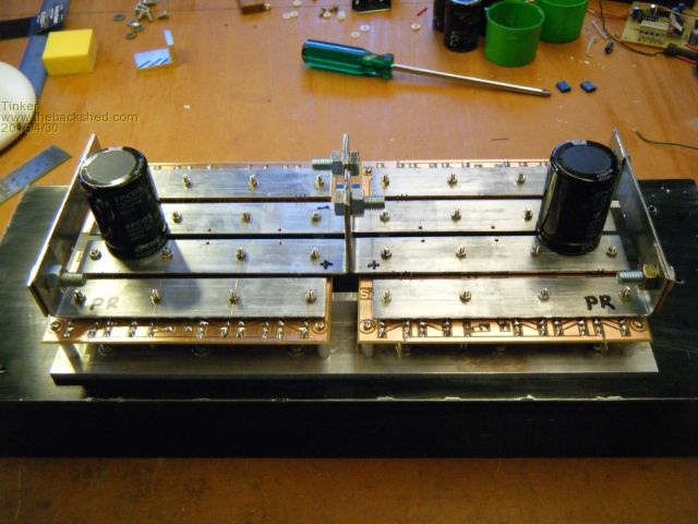
Only the gates connect to the PCB's,, the drain & source leads solder to the copper strips: 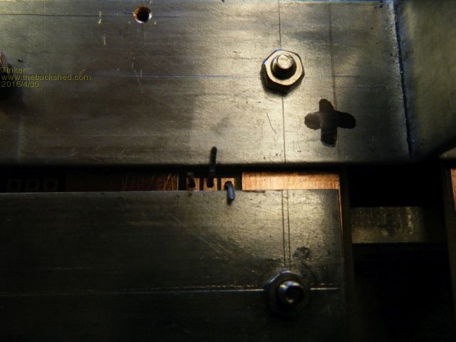
Add two more little boards and putting it all together: 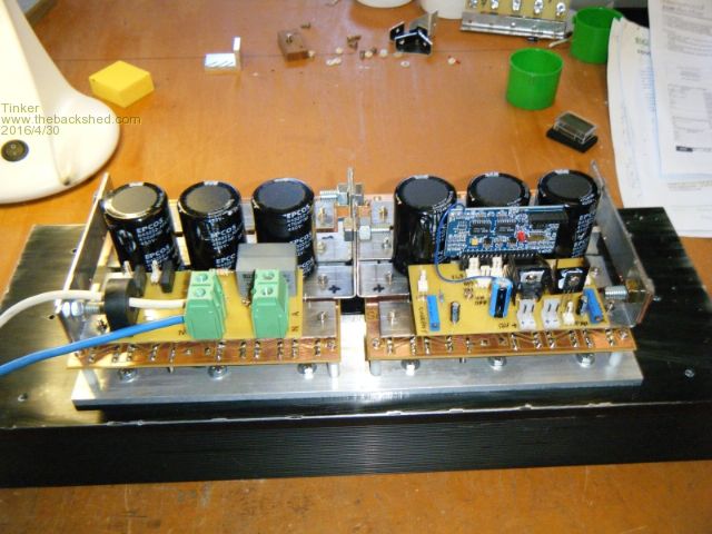
And that is it. Can't be more simple, its certainly way more compact than the PJ board assembly. And one is not committed to a particular heat sink, any flat back type big enough for the task would do. This can even be two heat sinks, some of them can fit together to make a bigger heat sink. The PCB's are simple single side 1oz boards, easily etched at home by those with the equipment to do so. Some more close ups: 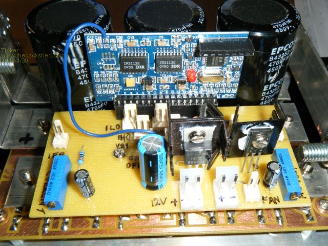
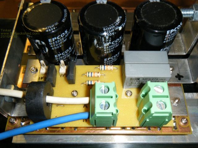
The eagle eyed among you will have noticed that the capacitors shown are high voltage, low capacity types. I'm still waiting for the 10,000uF/100V types but as they are of the same size I used the ones in the photo for this mock up. The lot has to fit in a suitable box and I was scratching my head where to get one (the double core toroid transformer is going to be too big to fit in the original Aero Sharp inverter box I have) until I spotted this at my local hardware store, (B...) 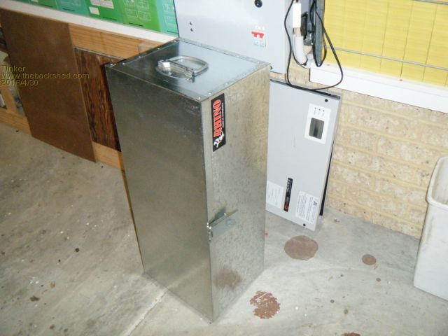
I think at just under $40.- this tool box will do fine. I need to fit some internal reinforcement at the bottom to carry the heavy toroid transformer and also remove those carry handles as the box is going to be used vertically. I will draw up a revised circuit (from the one shown at the beginning of this thread) in a little while, there are some minor additions only. Klaus |
||||
Grogster Admin Group Joined: 31/12/2012 Location: New ZealandPosts: 9307 |
My brother just installed a commercial solar system and 5kW inverter - 20 grand. I did not know he was going to do this. Inverter alone cost 8 grand of that. 12 solar panels. I did not have the heart to tell him that I have been looking into this stuff for a while now, and that it could have been done for less then half what he paid if we had built one of the 6kW units that people here have been building. I for one, will be very interested in your final schematic, Tinker, when you do post it. Smoke makes things work. When the smoke gets out, it stops! |
||||
oztules Guru Joined: 26/07/2007 Location: AustraliaPosts: 1686 |
Beautiful work Tinker... this will be much easier to mount and doubt it will need a fan 99% of the time. ..........ozules Village idiot...or... just another hack out of his depth |
||||
| Clockmanfr Guru Joined: 23/10/2015 Location: FrancePosts: 429 |
That's real nice Tinker. Interesting to see that you have gone the sub board route. Working on the new 6-15kw power board, I can see why PJ went the sub board way, especially when the board is pulling serious power. In places lots of copper is what we want. My 2oz + 2oz boards power board and control board are being produced in China as we speak, hopefully ?. I have really tried to keep things simple, uncomplicated and yet robust, but added extra large peculiar shaped areas of copper for plenty of solder spread in certain places. I now have a good ebay supplier of the right size heat sinks, http://www.ebay.co.uk/itm/391275496753?_trksid=p2057872.m2749.l2649&ssPageName=STRK%3AMEBIDX%3AIT that is better than Alibarber, who are incredibly slow at actually producing/procuring. I have ordered and received different 8010 chips, but still awaiting the HT1356 types. The "Making a Low cost, simple and robust 6kW, 50HZ Pure Sine Wave, 48vdc to 230vac, INVERTER" book, Non Profit Print +P&P cost only, is just awaiting a few photos from the new PCB boards and testing them. The full size PCB masks are finished and will go in the added insert supplement. Funny to see that Amazon has the book listed, ISBN number now! before I have even put up a link. 'Grogster', hopefully this book would give him enough knowledge /info to construct and build his own Inverter, it certainly puts the over priced so called RollsRoyce commercial Inverter that I first purchased to shame. (One PCB software guy recently said, "the silk screen looks like a Painting by Numbers", it, imported DXF file, kept crashing his software as it was detailed and a little bit to big) I have given a few books away. Now there are electricians making the OzInverter for their family communities back home, where there is no 230vac supply, in Morocco and Africa. Give me a few weeks..... Back to my BigOzInverter. Everything is possible, just give me time. 3 HughP's 3.7m Wind T's (14 years). 5kW PV on 3 Trackers, (10 yrs). 21kW PV AC coupled SH GTI's. OzInverter created Grid. 1300ah 48v. |
||||
| Tinker Guru Joined: 07/11/2007 Location: AustraliaPosts: 1904 |
Here is the updated schematic for the inverter described in this post: 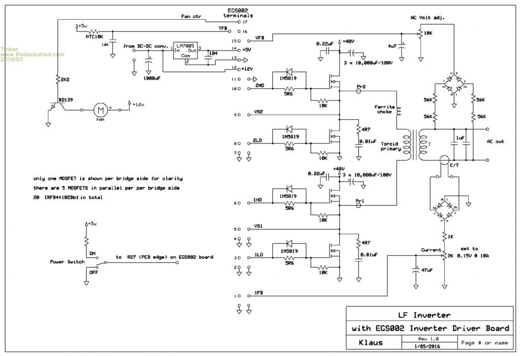
This drawing represents a collection of information and ideas I gathered from this and other forums. As I have not yet finished building this inverter I cannot vouch it will perform as anticipated, my test data will have to wait a while to appear here. I would appreciate if anybody notes errors in this schematic to let me know so I can correct them. Klaus |
||||
Grogster Admin Group Joined: 31/12/2012 Location: New ZealandPosts: 9307 |
Looks too simple to work!   
Nice. I await your results, but this does seem so simple....... Where did you buy your MOSFET's from? eBay or somewhere a bit more reliable? For something like this, where you would be working the MOSFET's hard, I would think that somewhere like element14 etc would be the way to go. More expensive, but you know you are getting genuine rated parts. Would you agree? Smoke makes things work. When the smoke gets out, it stops! |
||||
oztules Guru Joined: 26/07/2007 Location: AustraliaPosts: 1686 |
1. Would prefer to see 4r7 become 47r for the snubbers. 2. 47uf is quite high for the current capacitor, maybe 4u7 would be a bit ,more responsive....This needs to be juggled with how high a surge current you want... compared to where you want the current to stop the unit with the IFB.... ie it will introduce a time lag.... which is excellent for starting big loads. Transformer size may be the indicator for this ie set for 2kw continuous with 10kw surge would be a big cap with skinny setting point.. good for smaller tranny, .... or, we can set for 6kw continuous, with 18kw surge if we have big transformer.... here a smaller cap and wider set point would be the trick.... I use 4u7 now. Personal experience has been no name fets (test them first) work every bit as well as name brand, and when the thing fails from abuse of some sort, the name brand ones explode exactly the same as the no name ones... so I no longer have sticker envy. ........oztules Village idiot...or... just another hack out of his depth |
||||
Grogster Admin Group Joined: 31/12/2012 Location: New ZealandPosts: 9307 |
...provided you get the rated part.  I guess that is why you say test them first. Problem is, with lots of the eBay stuff, they incorrectly label it on purpose in order to sell it as something different. I got some LM338 regulators like that once - supposed to be able to handle 5A, labelled as LM338K, blows itself to bits with more then 1.5A. Cut the can open, and you can tell from the link wires to the die, that there is no way they EVER could handle 5A on those cat's whisker link wires, and the die is smaller then the 338 one should be.... I guess that is why you say test them first. Problem is, with lots of the eBay stuff, they incorrectly label it on purpose in order to sell it as something different. I got some LM338 regulators like that once - supposed to be able to handle 5A, labelled as LM338K, blows itself to bits with more then 1.5A. Cut the can open, and you can tell from the link wires to the die, that there is no way they EVER could handle 5A on those cat's whisker link wires, and the die is smaller then the 338 one should be....
However, I guess perhaps I was just unlucky, as other members here have said they have had a good run with eBay components. So, my concern is that the part may be labelled as a 97A MOSFET, but only capable of 10A or less - they just put the big part number on the case to trick you. As soon as you load them up, they will all go fut. Replacing them all is not my idea of fun, so I don't want to have to do that very often if at all. But as you say - test them first. However, that test is only valid for the one you are testing. To be sure, you would need to test each and every one, cos it would be really easy to get a fake anywhere in your lot. However, with a test rig, that would not be difficult or time consuming to do I suppose. You get what you pay for. I think I will just get the genuine element14 ones. At least I can be guaranteed that they are the genuine rated part. I will also check other component suppliers. @ Tinker - still interested in where you got your MOSFET's.  Smoke makes things work. When the smoke gets out, it stops! |
||||
| Tinker Guru Joined: 07/11/2007 Location: AustraliaPosts: 1904 |
Thanks oztules, I will take your suggestions on board, they are easy to do anyway. BTW, do you know how much power the EGS002 board draws when running? Reason for asking; is the 3A DC/DC converter (see below) big enough to run the board and a 12V, 1A fan? Grogster, like oztules I ordered the Mosfets from E-bay in a 50 piece lot. I intend to test each one and select 20 similar ones from them. There is a BIG price difference from the manufacturer's supplies and I'm aware I will have to take my chances. This little beauty turned up today: 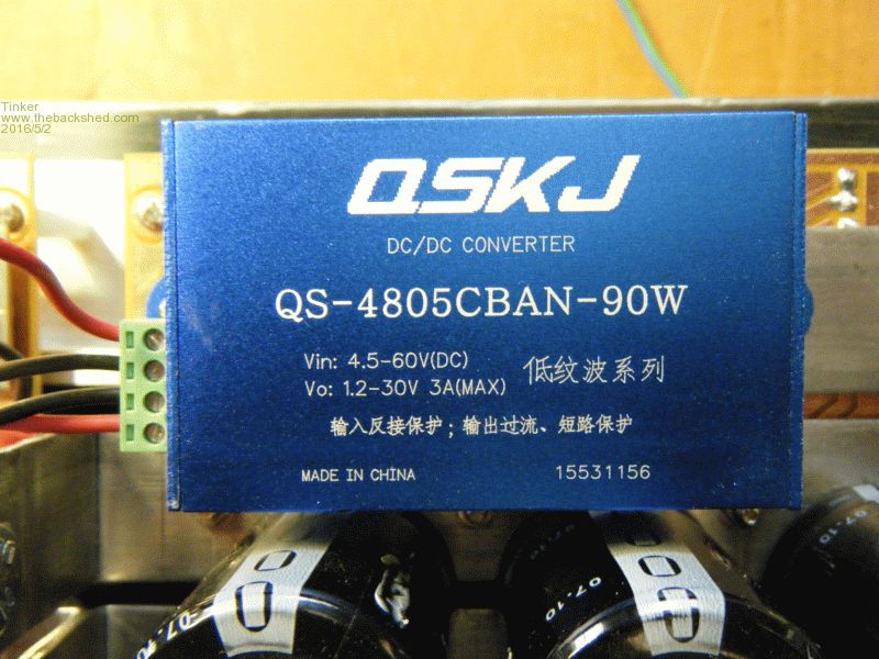
Its potted in a neat anodised aluminium extrusion and has a plug in terminal. I tested it by connecting to my 48V battery bank (sitting at 55V) and loading to 2 Amps @ 12V output. The case felt barely warm after 30 min, time will tell how it performs in the long run. I think its better than connecting a 12V regulator to 55V. I got it from here:dc/dc converter Klaus |
||||
oztules Guru Joined: 26/07/2007 Location: AustraliaPosts: 1686 |
The egs002 is in the order of 100ma or so from memory... so your converter will be fine.... bit skinny on the 60v, I got two of these for the same price.... 72v... http://www.ebay.com.au/itm/272150532644?_trksid=p2057872.m2749.l2649&ssPageName=STRK%3AMEBIDX%3AIT Arrived today, not had time to test yet. I push the equalise charge pretty hard from time to time.... so wanted the extra head room.... it was this or a tiny 240v transformer.... but at 7 dollars or so. It claims 10amps @ 12v.. we'll not be needing anywhere near that. ...........oztules Village idiot...or... just another hack out of his depth |
||||
| Tinker Guru Joined: 07/11/2007 Location: AustraliaPosts: 1904 |
Klaus |
||||
| Tinker Guru Joined: 07/11/2007 Location: AustraliaPosts: 1904 |
FYI, I just tested all 50 IRFB4410Z Mosfets I bought as a lot from ebay. The data sheet for these says the ON resistance is typical 7.2mOhm, max.9.0mOhm. They were all better than that, by a substantial amount. Results were (in milliOhms): 1 x 4.4 15 x 4.5 26 x 4.6 8 x 4.7 I'm happy with that. I tested them by passing 10Amps through each in turn and measuring the drain/source voltage. I tested one with a much higher current briefly, same result but the series resistor got too hot to test all at that higher current. Klaus |
||||
Grogster Admin Group Joined: 31/12/2012 Location: New ZealandPosts: 9307 |
Useful information. I might get the eBay ones afterall.... Smoke makes things work. When the smoke gets out, it stops! |
||||
oztules Guru Joined: 26/07/2007 Location: AustraliaPosts: 1686 |
They deserve to have their ebay add listed here please Tinker.. They are good figures indeed. .........oztules Village idiot...or... just another hack out of his depth |
||||