|

|
Forum Index : Windmills : f n p gridtie windturbine
| Author | Message | ||||
| rustyrod Senior Member Joined: 08/11/2014 Location: AustraliaPosts: 121 |
The "flywheel explosion test" test was actually tried by the Southern Cross foundry in Australia sometime around the 1950's. They apparently took one of their solid flywheels (presumably around the 20 inch range) and geared it up via a layshaft from one of their big diesels. They built a sandbagged enclosure to catch the bits but when it finally let go at 5300RPM the enclosure was destroyed and at least one major chunk travelled 500 yards horizontally.They didn't mention the vertical component! The flywheel was mounted horizontally to decrease the possibility of vertical debris. In fact one driver engine was not enough so Southern cross added an extra engine to power the test unit. All the facts are in the Southern cross history. Recently a small Iron Horse motor was running and had been revved up a few times then left to idle. The flywheel came apart. One piece went vertical through the roof of the very high commercial premises, another smaller piece went through a man's arm into his body. He was some distance away. He is all mended now. The other men were not harmed The flywheel was of a cast aluminum construction and quite old. Fortunately it did not fly apart when the men were close and revving it. The F&P Magnetic Rotatory drum in a such test, there would be a variable, First if the magnetic drum was new or second, had been exposed to sunlight. Obviously the rotation of the F&P in the washing machine on the spin cycle is quite within their specifications. Could apiece of the plastic be tested for "tearing" then weigh a magnetic section and calculate the centrifugal force required to increase the magnets to their destructive weight? I am impressed with your setup especially that you have geared up one F&P. The mechanical engineering must be awesome. Well Done! Always Thinking |
||||
| flc1 Senior Member Joined: 20/11/2011 Location: New ZealandPosts: 242 |
Gday Rustyrod, thanks for the compliment on my windturbine, the gearing on it is just 2 pullys and a v belt, 2 shafts, ,,,,Im looking at putting 3 stators onto one shaft, when this current setup needs repair or whatever. Might have a change around, I think I will get away with 3 stators on direct drive with the blade size and number of blades on it now,and have just the single shaft, no second shaft...should get about 1.5kw out of it?? just trying to find a bearing block that has the same mounting holes as the f n p stator,,might have to make one |
||||
| yahoo2 Guru Joined: 05/04/2011 Location: AustraliaPosts: 1166 |
I cant find chris olsons original build posts so this will have to do. from memory it was first posted on fieldlines it is his first chain driven axial flux build. the cogs, chain, self centering bearings and locking collars are all good quality standard issue off the shelf stuff. I dont remember how the blade hub and rotor were attached, I suspect it was with a taper lock centre. The only catch is the cogs would have a keyway cut into the shafts so there is a tiny bit of milling involved. Anyway, this is how I would build, most of the machinery I work with is based on this combination of parts, it is pretty bombproof, quick, standardised and cost effective. cheers I'm confused, no wait... maybe I'm not... |
||||
| flc1 Senior Member Joined: 20/11/2011 Location: New ZealandPosts: 242 |
thanks Yahoo2, thats a good solid looking piece of work, those bearing housings look like a two piece setup,,a front and back?? I think I will be useing somthing similar to that , they can have holes drilled to fit the stator. |
||||
| flc1 Senior Member Joined: 20/11/2011 Location: New ZealandPosts: 242 |
Heres a video of my turbine on youtube if anybody is interested...... https://www.youtube.com/watch?v=FcDe8FEmtoo |
||||
| govertical Guru Joined: 11/12/2008 Location: United StatesPosts: 383 |
Great, thanks for posting. just because your a GURU or forum administer does not mean your always correct :) |
||||
| domwild Guru Joined: 16/12/2005 Location: AustraliaPosts: 873 |
flc1, Thanks for that, most interesting. I assume you are not getting that princely sum of 6 cents/kWh (a WA figure) from the state as the Chinese grid tie I also want to buy is not built to AS/NZ standards; good luck to you! What worries me with those grid ties is the message that they disconnect from the grid on over voltage, I take it to mean they then dump it into the provided dump loads and batteries, but is that good enough? You relays then cut out the batteries when charged and the dump loads are the sole recipients. Ever thought of adding a H/W element? Taxation as a means of achieving prosperity is like a man standing inside a bucket trying to lift himself up. Winston Churchill |
||||
| flc1 Senior Member Joined: 20/11/2011 Location: New ZealandPosts: 242 |
Gday Domwild, ,, we get 7c per kw in the summer and 10c in the winter here, yep they dump into the dumpload resistor if there is a over voltage or grid drops out for sum reason,not sure if they dump everything into the resistor when theres an over voltage, or if they just dump the amount that is over the max, I would think it would be the later. but the dumpload seems to handle it ok.The dumploads glow yellow when they come in at high rpm from the grid switching off,when theres a drop in rpm the dumpload pulls turbine to a stop, and it seems to take alot more wind to get the rpm increasing again.they seem to do the job fine.I think the main thing with the gridtie inverters is that they disconect from the grid when the grid is turned off, so no linesmen etc get electrocuted, and these inverters do just that,which is good. I could get one of those water heater elements that can handle both ac and dc,or so the seller of the elements claims they can handle both?ha. I have thought about that, just means I have to run a couple more cables to the house. |
||||
| flc1 Senior Member Joined: 20/11/2011 Location: New ZealandPosts: 242 |
double stator setup.........with 1 stator removed, so I can repack bearing with grease. |
||||
| DaveP68 Senior Member Joined: 25/11/2014 Location: New ZealandPosts: 292 |
Hey Fred What a beautiful picture, a work of art that actually does something productive like producing up to 1.1 kW of power!! Good work, have to try catch up sometime to compare notes on our respective setups.. Cheers David There are realities if you do not accept, will lead to frustration because you will be spending time on wrong assumptions and the results cannot follow! The Dunning Kruger Effect :) |
||||
| domwild Guru Joined: 16/12/2005 Location: AustraliaPosts: 873 |
Hi, Am curious and you do not need to reply as I may be dobbing you in here but I want to do the same: To get those princely sums an electrician must have installed it I presume and then made application to the provider to pay for the feed-in, but an electrician may not install something, which is not AS/NZ approved. How did you get around that?? Taxation as a means of achieving prosperity is like a man standing inside a bucket trying to lift himself up. Winston Churchill |
||||
| flc1 Senior Member Joined: 20/11/2011 Location: New ZealandPosts: 242 |
Gday Dave, thanks for that, don't know about it being a work of art?lots of room for improvment ha, yea we must catch up. Domwild...my system is approved.If your not approved you don't get the full benefit of what you produce, your just giving electricity to the power company for free. we don't want to give them somthing for nothing. |
||||
| flc1 Senior Member Joined: 20/11/2011 Location: New ZealandPosts: 242 |
latest peak ac output is 1020watts, uploaded vid on youtube of turbines dumpload in operation, glowing bright orange white , https://www.youtube.com/watch?v=KBrZCZDM9hM |
||||
fillm Guru Joined: 10/02/2007 Location: AustraliaPosts: 730 |
For a dump load to be glowing like that means it is the wrong size and rating and is tempting fate especially on a plywood wall. A dump load should be able to take the turbine power and dissipate it and not get to the glowing and meltdown stage. I would say try use 4 of those ceramic 2 x 2 in series and then parallel connected. PhillM ...Oz Wind Engineering..Wind Turbine Kits 500W - 5000W ~ F&P Dual Kits ~ GOE222Blades- Voltage Control Parts ------- Tower kits |
||||
| flc1 Senior Member Joined: 20/11/2011 Location: New ZealandPosts: 242 |
Thanks Phill, the glowing comes only at or near peak rpm ,peak output, but I agree that I need to increase the dumpload size,it may not last long like that in a severe storm if the grid is shutdown, these dumploads seem to be similar design to the old bar heaters we used for heating years ago, which glowed red all the time while in use..the plywood is temparary housing untill I get around to building a better one. I have another inverter with dumpload hooked up to turbine aswell, but its not switched on. |
||||
| flc1 Senior Member Joined: 20/11/2011 Location: New ZealandPosts: 242 |
have ordered more resistors to upgrade dumpload as you suggested Phill, thanks for the good advise. |
||||
| DaveP68 Senior Member Joined: 25/11/2014 Location: New ZealandPosts: 292 |
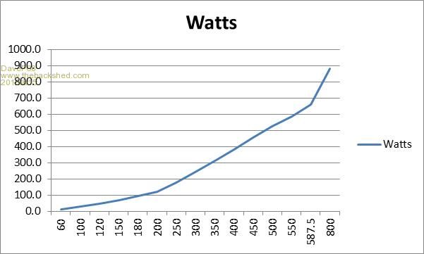
Hi Fred Here is a power output graph of a single 36 pole Delta F&P stator with black rotor cap operating under optimum conditions. RPM is on the horizontal axis. 
If you see graphs with a steeper curve the stator is operating outside it's optimum operating output. Cheers David There are realities if you do not accept, will lead to frustration because you will be spending time on wrong assumptions and the results cannot follow! The Dunning Kruger Effect :) |
||||
| flc1 Senior Member Joined: 20/11/2011 Location: New ZealandPosts: 242 |
thanks for that David, some more good data |
||||
| flc1 Senior Member Joined: 20/11/2011 Location: New ZealandPosts: 242 |

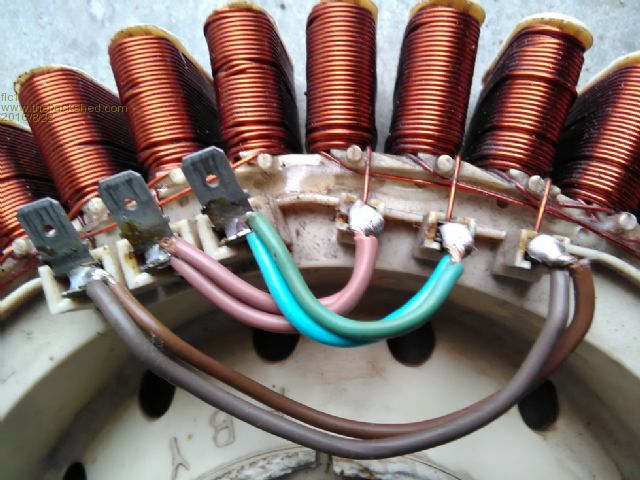
photo of a stator that is uncut and wired in delta |
||||
| flc1 Senior Member Joined: 20/11/2011 Location: New ZealandPosts: 242 |

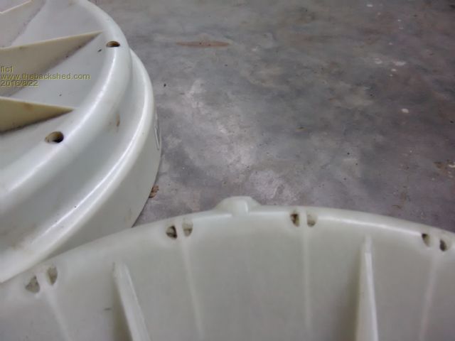
photo showing the diffrence between a arrow head f n p rotor cap and a standered f n p rotor cap, the arrow head rotor has 5 small knobs around the outside edge of the rotor cap, knob can be seen in photo, the standered older type rotor cap in backgound. Arrow head rotors have very little cogging because of the arrow head shaped magnets,as explained on other pages in the back shed forum,and the 36 pole comes from the factory with rounded pole ends( all ready decogged), good for windturbines. The black f n p rotor cap is usually on a aluminum stator,so if you come across a f n p washing machine at the dump and it has a arrow head rotor cap, it will most likely be a copper wound 36 pole stator,thats good,and one with the black rotor cap will most likely be a 36 pole aluminum wound stator,so grab the black rotor cap(can be hard to remove because of stronger magnets) but leave the stator that it is on,most likely aluminum windyings,good for nothing. The aluminum stator usually has the letters A L stamped on it. The black rotor cap can give you about 20% more power out of a 36 pole copper stator when compared to the arrow head rotor cap. hope this info is of some use to sombody. |
||||