
|

|
Forum Index : Electronics : Building a new Inverter.
| Author | Message | ||||
Grogster Admin Group Joined: 31/12/2012 Location: New ZealandPosts: 9308 |
Are they the cores linked to in the 5th from bottom post on the fieldlines thread? I am enquiring at a few New Zealand based transformer companies about cores, and this is one of the sizes I am asking after. I am also asking about rolls of 2mm enamelled copper winding wire, as this will allow me to wind a transformer here, WITHOUT having to unwind an old one - less work, less stress. 
I am intently interested in this home-bake inverter, as I almost wasted a tidy packet on a 10kW eBay inverter, but other members here warned me off that, and I am so glad they did, as most of those high-power inverters can't do anything like the continuous load they say they can, so it would seem by reading around the web... 
I look forward to your next batch of photos.  Smoke makes things work. When the smoke gets out, it stops! |
||||
| brucedownunder2 Guru Joined: 14/09/2005 Location: AustraliaPosts: 1548 |
Very neat ,Glenn. What a great idea that bending tool and wedge .. I have mine in use 24/7 under light load and it is working perfectly. I now and then turn my heat gun on and that stirs it up a bit ,but no big deal. Bruce Bushboy |
||||
| Gizmo Admin Group Joined: 05/06/2004 Location: AustraliaPosts: 5078 |
Hi Grogster There are two "cores". One is the big toroidal transformer that can be sourced from the Inspire ( or similar ) inverters, or you can buy the bare core and wind it from scratch. The other is a smaller ferrite which we use as a choke, see the 2nd page of the fieldlines thread, top post http://www.fieldlines.com/index.php/topic,148717.27.html?PHPSESSID=279b8ea72bb6830aa9698417ddf5b515. We need both. Thanks Bruce. Hope to get mine up and running before the storm season. Glenn The best time to plant a tree was twenty years ago, the second best time is right now. JAQ |
||||
Grogster Admin Group Joined: 31/12/2012 Location: New ZealandPosts: 9308 |
My NZ based transformer company can supply a pre-wound toroid: To me, this sounds like a good deal, and nowhere near the $1800 suggested in the other forum thread, and it would be professionally wound - just not having to unwind and rewind the bloody toroid is good enough reason for me, just about! 
What are the other members opinions on that price, bearing in mind that you get back a professionally finished and wound core with two-in-hand 2mm, and then you just have to wind on the thick primary - job done. Smoke makes things work. When the smoke gets out, it stops! |
||||
| gpalterpower Senior Member Joined: 19/07/2009 Location: AustraliaPosts: 175 |
Hi all, very interesting thread here. I have been wondering for quite some time now if you can convert a Grid Tie Inverter into an off grid inverter. Seems you can!! But i'm guessing it has to be a particular variety of GTI. One with a toroidal inside. My question is ...do toroidals have to be manufactured from ferrite or could they be constructed from layers of say 1mm large flat mild steel discs to make a stack as high as you want to! Similar as an "E" type construction or any other stator or armature to reduce eddy's. I ask this crazy question because I have acces to these large discs at work. Reacon I could make something from them.  I have electrical powder coating material and could cover the stack with the high temp, high electrical insulation coating. I have electrical powder coating material and could cover the stack with the high temp, high electrical insulation coating.
Marcus if it aint broke dont fix it!! |
||||
| Gizmo Admin Group Joined: 05/06/2004 Location: AustraliaPosts: 5078 |
Grogster if you can find a Inspire 2.5kw model like mine, then it comes with a transformer that has the 2 in hand 240v winding, you just need to remove the outside winding to get to it. I paid $125 for mine, so hunt around and you could find one yourself and save a few hundred dollars. Marcus the big toroid used in this inverter has a steel core, not ferrite. The steel used is a special case, designed for transformers, and laminated, each layer insulated from each other. Building one yourself would be a lot more work than first thought. Glenn The best time to plant a tree was twenty years ago, the second best time is right now. JAQ |
||||
| Tinker Guru Joined: 07/11/2007 Location: AustraliaPosts: 1904 |
Marcus, no, disks are no good for that application. Think about how the magnetic lines inside a toroid transformer core are aligned. They go round and round as if trapped inside the dough of a donut. Your disks would provide a nice short for the magnetic lines to heat up. What you want to do is to interrupt any circulating induced current in the core. This is done by layering the core material toilet roll style. Just a very long strip of coated sheet material, rolled up. Klaus |
||||
| gpalterpower Senior Member Joined: 19/07/2009 Location: AustraliaPosts: 175 |
Gizmo and Tinker. I understand where you are coming from now. I had no idea how they worked so thanks for enlightening me. As I said, it was crazy question. The irony of it all is that I purchased and just had delivery of a 3kw 24v power star inverter the very same day as I first saw this thread. I just hooked it up this arvo to see how she works. So far so good and read some good blogs about them previously as a robust item, but I believe they draw some current on standby. Marcus if it aint broke dont fix it!! |
||||
| Gizmo Admin Group Joined: 05/06/2004 Location: AustraliaPosts: 5078 |
A quick update. Will put together a post with more detail at a later date. Transformer with its new primary. Red wire is 25mm square. Its heavy, thats a bar stool its sitting on so you can get an idea of the size. 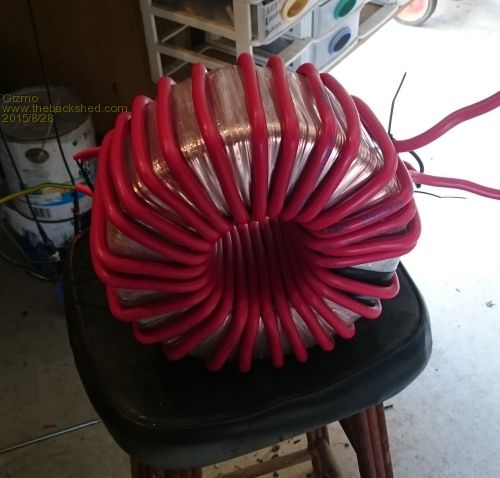
The ferrite coil halves and former arrived a few days ago, this is the choke I wound. I made a hardwood timber jig to support the former so I could wind the 25mm wire, its not easy to bend. 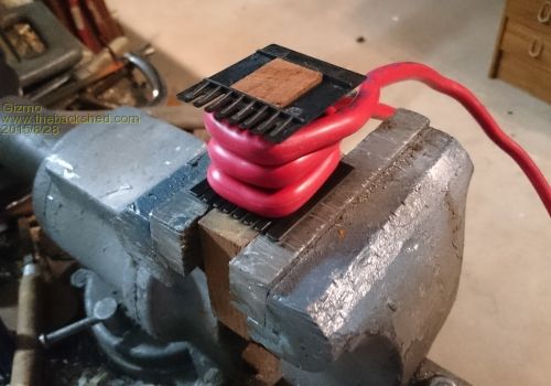
The partly assembled inverter. 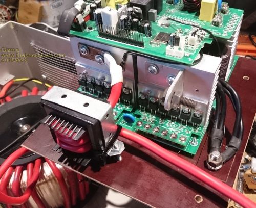
Oztules sent this to me, its the pin connections needed to get the control card to start up. I used a couple of transistors to buffer the alarm and power led outputs, will draw a circuit at a later date, but basically a 15k resistor to the base of a C548 transistor, Emitter to ground, Collector to a led via a 680ohm resistor, to +12v. 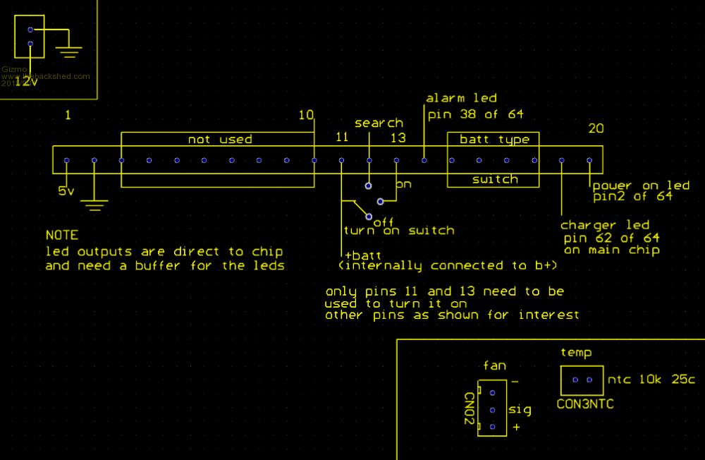
Almost finished. 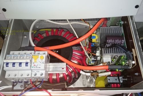
First test run. Used a 16amp breaker on the 50V input as a precaution. Had to reset it a few times as the big capacitors charged up. Inverter fired up no problem, here's its powering a 60watt bulb. 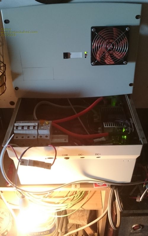
More to come in a day or two. Glenn The best time to plant a tree was twenty years ago, the second best time is right now. JAQ |
||||
| Gizmo Admin Group Joined: 05/06/2004 Location: AustraliaPosts: 5078 |
Done a little testing. During the first tests the inverter drew 1.3 amps idle ( no load on the 230vac output ), at the time the battery voltage was 58, so thats 75 watts. After reading the posts on Fieldlines, Another Power and Energy Matters, I knew I could get this value down. Oringinally I had fitted plastic spacers between the ferrite cores, took these out and retested. Idle current dropped to .59amps at 54 volts, 32 watts 
That's comparable to my expensive Latronics inverter, it draws .49 amps at idle. 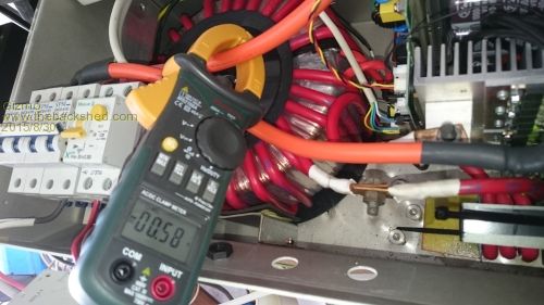
Connnected up the 60watt bulb and battery current was 1.68, or 90watts. Taking into account the 30 odd watts to run the inverter, it looks like its pretty efficient under light loads, which is important. 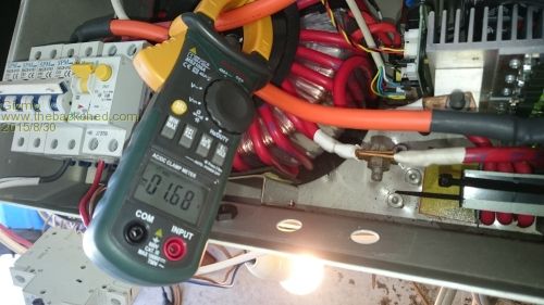
Have to say I'm pretty happy with the results. All up the inverter owes me about $650, and should supply 3kw to 4kw continuous. Next up is some housekeeping, tidy up a few things and add an additional fan to circulate air within the case. Then I'll wire it up with some heavy cable to the battery bank and give it a good load test. This is the transistor LED driver I used to drive the Power and Alarm LED's. 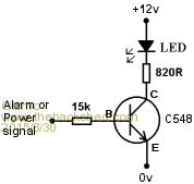
Glenn The best time to plant a tree was twenty years ago, the second best time is right now. JAQ |
||||
| yahoo2 Guru Joined: 05/04/2011 Location: AustraliaPosts: 1166 |
I have been trying to come up with a witty play on the Latronics name for your inverter Glenn. Drawn a blank so far. Have you looked inside one? I guess there is not too many ways to peel a banana but it looks like they could be brothers. 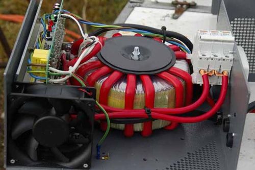
I'm confused, no wait... maybe I'm not... |
||||
| Gizmo Admin Group Joined: 05/06/2004 Location: AustraliaPosts: 5078 |
I was thinking Frank, short for Frankenstein. Never pulled the cover off my Latronics, been tempted from time to time. Once I get "Frank" in place I might have a look in the Latronics. Thanks for the picture. The best time to plant a tree was twenty years ago, the second best time is right now. JAQ |
||||
| Gizmo Admin Group Joined: 05/06/2004 Location: AustraliaPosts: 5078 |
Inverter is finished. Here's a couple of pictures of my "power wall". We have the windmill rectifier and control, the solar controller and the 240VAC power board. 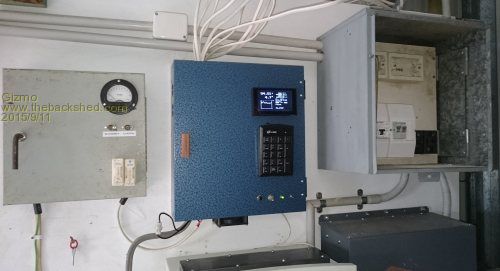
And here is the 50v common connectors, new "Frankenstein" inverter and the Latronics inverter. 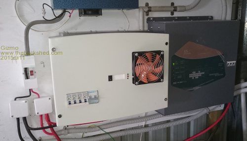
I've had the new inverter running off and on over the last couple of days. Only issues were a over voltage alarm when the batteries were boosted to 60v, and a shutdown due to a faulty cooling fan, the fans tac output needed a pull up resistor to give the correct signal. The new inverter makes less noise than the Latronics, the toroidal is dead quiet, all I hear is a dull squeal from the ferrite choke. I've updated the pin out diagram in the post further up the page. It showed pins 1 and 2 as 12v, not the case, they are 5v and should not be used as this is the same bus as the CPU. There is a 12v feed on the little 2 pin connector at the opposite end of the control board to the fan/temp connectors. Glenn The best time to plant a tree was twenty years ago, the second best time is right now. JAQ |
||||
| Tinker Guru Joined: 07/11/2007 Location: AustraliaPosts: 1904 |
Thanks for posting that nice project Glenn, I'm still looking for a suitable toroid core so I can build an inverter like yours. Is there a reason you used a 4 pole circuit breaker or is it something you just had at hand? Klaus Klaus |
||||
| Gizmo Admin Group Joined: 05/06/2004 Location: AustraliaPosts: 5078 |
Hi Klaus I get some wild electric storms around here so I like to have as many open circuit paths as practical. It is overkill. There are 4 63amp circuit breakers for the 50V DC, two for the +ve and 2 for the -ve. I made the cross bar so all 4 are switched at once. In effect, its a big 126amp circuit breaker. On the AC side I have a single dual pole 25amp breaker to isolate both N and A. The AC then goes to my power board, where it goes through a dual pole mains switch. Each inverter has its own dual pole mains switch, so I can switch one off and one on. Ideally I should be using a dual pole change over switch to avoid accidentally having both inverters switched together. That could be very bad. After that the mains has its N earthed, and fed to the earth leakage breakers, one for power and one for lights. After that there are further smaller breakers for the individual circuits. Glenn The best time to plant a tree was twenty years ago, the second best time is right now. JAQ |
||||
| Tinker Guru Joined: 07/11/2007 Location: AustraliaPosts: 1904 |
Overkill eh?  your words your words  . .
You are right by not switching two individual inverters into the same circuit, I wish there was a simple way to synchronise their frequencies as I have a similar set up. In my place there are two AC circuits, one for the house and another for the shed. The smaller inverter runs a few items in the shed. I have an electronic KWh meter that uses current transformers to record what I generate from my solar panels. One C/T is connected to each inverter, they isolate the circuit they measure. Watching the meter when, for example, the shed fridge runs at the same time than the house fridge I can see the Amp reading (on the KWh meter) drift up and down as the inverter frequencies get in and out of sync. Thanks for the information, its appreciated and I'm always keen to know how others connect things up. Klaus |
||||
| gpalterpower Senior Member Joined: 19/07/2009 Location: AustraliaPosts: 175 |
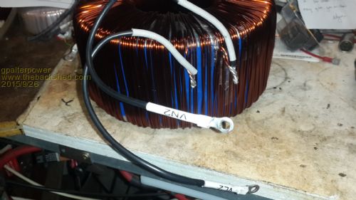
Well after seeing Glenns and Bobs projects completed I truly was "inspired" ( no pun intended) . What a great job by both of you guys. I can only hope my project will turn out just as good . I travelled to Brizzy on the weekend and picked up the ebay 2.5 inverter for $100 along with some solar panels. Man..she..is..heavy. Couldn't wait to get it home and open it up. Even the guys at work said "That is a massive toroidal". After removing insulation I noticed it wasn't the same as in your pics Glenn. The outer layer was only 2 in hand. Not the 4 in hand as I hoped for. Mmmm. Not an ah-ha moment... more like an OOOOH moment!. Could there be 2 types of toroidals ?Wound in reverse maybe ? Somehow I think I have a larger job ahead of me as the pics show. Any ideas? Marcus 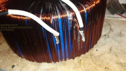
if it aint broke dont fix it!! |
||||
| Gizmo Admin Group Joined: 05/06/2004 Location: AustraliaPosts: 5078 |
Hi Marcus Sounds like there may be a few different transformers out there, and I got lucky. How big is the hole in the centre? If its big enough to fit the 30 or so turns of 25mm wire ( about 9.5mm diameter including insulation ), then you could leave the existing coils in place and just wind over the top. Not as pretty, but it would work fine as far as I know. Glenn The best time to plant a tree was twenty years ago, the second best time is right now. JAQ |
||||
| yahoo2 Guru Joined: 05/04/2011 Location: AustraliaPosts: 1166 |
Hi Marcus, i have to admit Glenns toroid had me confused cos i thought the 2.5kw unit was as you describe and the cherry for ease of winding was the 1.5kw inverters. Perhaps there is an early and late model version or a change of toroid supplier during the build life. I'm confused, no wait... maybe I'm not... |
||||
| Gizmo Admin Group Joined: 05/06/2004 Location: AustraliaPosts: 5078 |
I would also do the voltage ratio test, so you know what exactly you have there. Connect up one coil ( the 2 in hand one ) to 240vac with a 60 watt incandescent light bulb in series. If you dont use the bulb, you will blow the house circuit breakers. Measure the voltage across both coils. Be careful. Glenn The best time to plant a tree was twenty years ago, the second best time is right now. JAQ |
||||