|

|
Forum Index : Microcontroller and PC projects : MuP
| Author | Message | ||||
bigmik Guru Joined: 20/06/2011 Location: AustraliaPosts: 2914 |
Hi Greg, I have to admit you are right... I only submitted the PCB to the PCB Fab 2 weeks ago exactly.. Considering Anzac day public Holiday as well, pretty impressive.. I often wait more than that for stuff to be just posted (supposedly) from Aus companies. Yes Vasi suggested the pullups and links but realistically, where would I fit them without the jumpering section around J6-J8 being very crowded and confusing..?? The 1k Resistor is the one thing I feel like adding and a jumper to short it out if not wanted. I do agree with the 0.1" spacing of headers and I generally try to do that but I have been learning AUTOTRAX DEX and I wasnt really proficient with it, I struggled with many things in the learning process and this was one that I missed. I DID finish the PCB whilst I was away on Holidays so I had to juggle PCB work and family as well as the new PCB program. One thing I did make sure of was that the two headers (J4 and J5) WERE on even 0.6" centres so you could plug it into a matrix board. I have thought about a daughter board to plug in to provide USB-TTL and maybe LEDs etc but I am wondering what would be the point if that was all I was to put on it. My stock is dwindling away and I have contacted SITOPWAY for a cost on re-runs of the PCB. They got back to me and the cost is the same and as China closes for 3 days starting tomorrow, I have till next week to think of what I can do to enhance the board, if indeed I do a Ver 2. I am still happy with it as it stands and I hope those that put their faith in me that bought them will be happy as well. Regards, Mick Mick's uMite Stuff can be found >>> HERE (Kindly hosted by Dontronics) <<< |
||||
| JohnS Guru Joined: 18/11/2011 Location: United KingdomPosts: 3817 |
If people want those things adding.... can't you just make the boards a bit bigger? I gather that's heresy but don't know why. John |
||||
bigmik Guru Joined: 20/06/2011 Location: AustraliaPosts: 2914 |
Hi John, Not heresy... I CAN make the board a bit wider I wanted it to be below 50mm x50mm and I have 6mm to spare one way.. It is something to think about..... I have just been playing around with some 3v3 cables I just picked up from Don. Dontronics 3v3 Cable and they are absolutely magnificent.. I had to change the wiring on the plug to suit the MuP (left CTS/RTS unconnected and juggled the position of the VCC (which is 5V) and RX/TX).. And they worked straight away.. Even on my WIN8.1 box.. I will get stuck into finishing the manual and see what I can do to improve the functionality in a Ver 2. Regards, Mick Mick's uMite Stuff can be found >>> HERE (Kindly hosted by Dontronics) <<< |
||||
bigmik Guru Joined: 20/06/2011 Location: AustraliaPosts: 2914 |
Gday Lads, Lasses, Bald headed babies, I know its only been 2 days since the MuP was available but I still feel bad that there wasnt a manual on offer. Well Here it is, finally. It may change and I am open to criticism so that we can all benefit. I tried to do photos to replace a lot of the screen captures of the PCB but personally I felt that the screen captures looked better. All in all I am quite happy with how its panned out. Damn... Max file size for upload is 500kb Mine is 1MB Temporally I have put in on my system (just a USB stick in my Router) but it ultimately cant stay there forever.. When I get a better place to publish it I will update the location here. MuP Manual Regards, Mick PS. There is a small MP4 file there ... a left over from Christmas... Look at it if you like but dont blame me if you feel nauseated after watching it.. 
Regards, Mick EDIT*** Thanks to the generosity of TassyJim, offering to host the MuP manual, I have a new permanent home for the manual. It can be found Here. I will keep mine going in parallel for a week or so. Thanks again Jim, Regards, Mick Mick's uMite Stuff can be found >>> HERE (Kindly hosted by Dontronics) <<< |
||||
bigmik Guru Joined: 20/06/2011 Location: AustraliaPosts: 2914 |
Lads, MuP ERRATA I am in the process of redesigning MuP V2 to add the options of Pullups on I2C and a 1k Resistor in the Rx line to allow a 5V TTL converter to be used. In the process I have discovered that the labelling of the I2C header block J6 is reversed. (J7 is OK) The correct Order should be Dat Clk 3/5 Gnd (I had Clk Dat 3/5 Gnd) My humble apologies to anybody tearing out their hair trying to work out why their I2C wasn't working. Regards, Mick (humbly flagellating myself) 
Mick's uMite Stuff can be found >>> HERE (Kindly hosted by Dontronics) <<< |
||||
TassyJim Guru Joined: 07/08/2011 Location: AustraliaPosts: 6103 |
Updated manual now available. It can be found Here. Jim VK7JH MMedit  MMBasic Help |
||||
| ajkw Senior Member Joined: 29/06/2011 Location: AustraliaPosts: 290 |
Mick, My boards arrived today, they look great. Many thanks! Now waiting for the brains from Silicon chip and some other bits from China in order to put them to work. No worries with the clk-dat-clk. Cheers, Anthony. |
||||
bigmik Guru Joined: 20/06/2011 Location: AustraliaPosts: 2914 |
Gday Anthony, Glad to hear that. Sorry about the Clk-Dat-Clk I can't believe I did that .. I checked it several times and still got it wrong.. Regards, Mick Mick's uMite Stuff can be found >>> HERE (Kindly hosted by Dontronics) <<< |
||||
MicroBlocks Guru Joined: 12/05/2012 Location: ThailandPosts: 2209 |
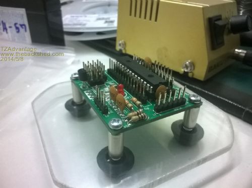
Mick, What would be the correct way to program and power the Mup from a PicKit3 when VR3 is mounted? If i connect the PicKit3 then both led's are on indicating that current is flowing from the 5v line through the red led. That means there is a current going through the Voltage regulator. I measured 3.2v on both 3.3v and 5v nets. The 5v net gets enough current for at least the led. I don't see another way to solve that then adding a jumper between the Voltage regulators Vout and the Vcc net. In the block diagram of the MCP1702 there is a diode allowing current going from Vout to Vin. I did not measure a voltage drop. If nothing else is connected to the Mup, i think it would not be a problem at all. I programmed the chip without any problems. Mentioning it in the manual to disconnect everything before connecting it to the PicKit3 would be sufficient. BTW (also for Paceman (i tested it first to make sure they work) i used a 10uF Multilayer ceramic X5R 1210 smd chip capacitor and it works fine. They are about $0.20 and i have got a reel of those. Here it is ready for action! 
Microblocks. Build with logic. |
||||
bigmik Guru Joined: 20/06/2011 Location: AustraliaPosts: 2914 |
Hi TZ, It looks like your PCBs arrived by looking at your Picture. I have been using the MPlab IPE which doesnt seem to have an option to power the target from the PICKIT so I supply power to the MuP and use the IPE to program the uMite. Honestly all this IDE and IPE (well actually IDE) is a bit alien to me and I cant get the IDE to program under win 8.1, someone else here recommended the IPE and that works, and is easy enough to use, but as I mentioned use another source to power the MuP. I did notice that once when I supplied a 3v3 supply to the MuP as the power source and I had VR2 installed that both LEDs lit... I wondered about that one but in my instructions I mention NOT to connect 3v3 as a power source when you have a VREG fitted.. I personally like the VREG and use a 5V source to supply the MuP. Regards, Mick Mick's uMite Stuff can be found >>> HERE (Kindly hosted by Dontronics) <<< |
||||
bigmik Guru Joined: 20/06/2011 Location: AustraliaPosts: 2914 |
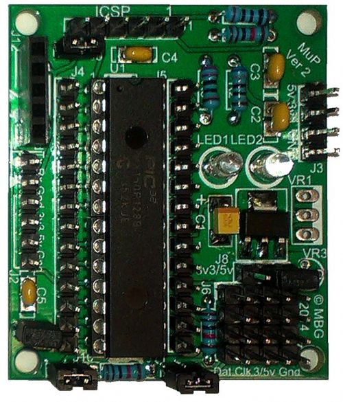
Gday All, As Ver 1 of MuP had no pullups for I2C and had an error on the overlay for Dat/Clk pins, I have redesigned MuP and released a Ver 2. MuP Ver 2 is identical in size to Ver 1 but is a much more useful board. Here is a photo of MuP Ver 2: 
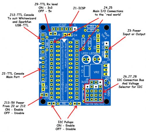
Changes from Ver 1 include: 1. Pullups for the I2C lines Dat & Clk with link options (J10,J11) to enable or disable them. 2. The addition of a 1k resistor to enable 5V TTL level Tx(in) to be used, this can be jumpered out (J9) if 3v3 TTL Tx(in) is to be used. 3. Fixed a silk screen overlay error that had the Clk and Dat labels for I2C reversed. 4. Added a new header location (J12) to support WhiteWizard’s USB module. 5. Added a Jumper (J13) to enable or disable 5V from the USB-TTL module inputs (J2 & J12). If MuP V2 is being supplied power through J3 AND a USB-TTL cable or adapter that has a 5V supply is connected, then J13 needs to be removed so that the two power sources will not `fight’ with each other. If 5V Power is required to be supplied via J2 or J12 then the jumper J13 will need to be installed. Jumper Layout can be seen here. 
I have asked TassyJim, if he is still willing, to kindly offer to host the new Manual for MuP Ver2 on his site. When it is available either he or I will post a link here. In the meantime if anyone desires a copy of the manual PM me with an email address and I will send it to you (1.3MB in size, so TBS forum wont let me post it directly here -- 500kB max allowed.) Regards, Mick EDIT*** The Manual for the Ver 2 MuP Can be found here: MuP V2 Manual Mick PS. Thank you once again Jim for hosting the manual. Mik Mick's uMite Stuff can be found >>> HERE (Kindly hosted by Dontronics) <<< |
||||
TassyJim Guru Joined: 07/08/2011 Location: AustraliaPosts: 6103 |
Link to the V2 http://www.users.on.net/~tassyjim/stuff/MuP%20PCB%20V2.pdf V1 is still available at http://www.users.on.net/~tassyjim/stuff/MuP%20Manual.pdf Jim VK7JH MMedit  MMBasic Help |
||||