|

|
Forum Index : Microcontroller and PC projects : GPS Module
| Author | Message | ||||
| BobD Guru Joined: 07/12/2011 Location: AustraliaPosts: 935 |
The white label on the DX supplied modules may be a serial or batch number. I have 310432 and 310659. I seem to have discarded the labels on the anti-stat bags. |
||||
| Geoffg Guru Joined: 06/06/2011 Location: AustraliaPosts: 3194 |
Probably a better chip to use in this case would be the MAX3232. It will work with a 3.3V supply (same as the GPS module) and will work with standard garden variety non polarised 100nF caps (the same as used in the Maxmite for decoupling the supply lines). Geoff Geoff Graham - http://geoffg.net |
||||
palcal Guru Joined: 12/10/2011 Location: AustraliaPosts: 1873 |
For those who bought the EM-408 from DX they also have a 'Mini RS232 to TTL converter' Cost is about $A1.90 it uses the MAX3232 chip. Much cheaper than buying the chip by itself. Paul. "It is better to be ignorant and ask a stupid question than to be plain Stupid and not ask at all" |
||||
| JohnS Guru Joined: 18/11/2011 Location: United KingdomPosts: 3805 |
Geoff - Thanks. Paul - also thanks (wish I'd known ...) John |
||||
| paceman Guru Joined: 07/10/2011 Location: AustraliaPosts: 1329 |
Thanks Paul - unfortunately I ordered a couple of chips from Element14 last night at $2.60ea  Anyway, I'll get a couple of these DX ones - they're a steal at that price and no extra mucking around with the caps. Anyway, I'll get a couple of these DX ones - they're a steal at that price and no extra mucking around with the caps.
Greg |
||||
| paceman Guru Joined: 07/10/2011 Location: AustraliaPosts: 1329 |
Errr... I should have been quicker - they're now sold out! |
||||
| BobD Guru Joined: 07/12/2011 Location: AustraliaPosts: 935 |
All is not lost. RS232 to TTL converter At 9.4mm x 15.9mm they appear to be not much bigger than the MAX3232CSE chip. The soldering looks a bit rough. |
||||
| paceman Guru Joined: 07/10/2011 Location: AustraliaPosts: 1329 |
Nice find Bob - thanks. Greg |
||||
| Lorenzo Newbie Joined: 27/08/2013 Location: FrancePosts: 17 |
Hi all, Excuse for this simple question from the newbie I am, but : If I understand correctly all posts, it is impossible to directly connect the RS-232 version of EM-408 on the RS-232 port of a MAXIMITE or CGCOLORMAX2 card. Even if I put the max232 on the CGCOLORMAX2 card ? And this, because of excessive voltage distilled by the output of this GPS ? What upsets me : An RS-232 port is an RS-232 port ... right? Normally you can put on him any peripheral rs-232 because is a standard ... The GPS EM-408 does not meet this standard ? or it's the MAXIMITE and CGCOLORMAX ? It sucks !!! 
Lorenzo |
||||
| 2001cpx Regular Member Joined: 03/10/2013 Location: CanadaPosts: 59 |
Hi Lorenzo, Check on Wikipedia,you will have all your answer. regular rs-232 peripheral,devices with isolated chip (max232),can be connected directly to computer comport,etc. voltage swing ((6,-6 to 12,-12)is useful for long cable and isolation protect your primary devices. with devices with max232,you can plug directly to your comport on PC. if you have gps module,xbee,etc with no max232(or other),you can plug directly to pic micro,(((directly without cable,on same pcb))),(check for voltage of devices,ie possibly need to add voltage divider on RX,if not tolerant) ex Xbee work on 3.3v ,i can plug directly to port of cgcolormax or maximite. Uc work at 3.3v simply buy allready made or make your own level translator. check on Google,write MAX232 and click image,you will have schematics,etc hope this help "Color Maximite,(Duinomite-Mega,Mini),CGmmStick,GCmicroboard2b,Micromite + explore 64,100,LCD backpack,Lcd Backpack V2,TFT Backpack,Micromite Extreme,Armmite L,F,H,CMM2" |
||||
| paceman Guru Joined: 07/10/2011 Location: AustraliaPosts: 1329 |
You have that a bit wrong Lorenzo. If you solder the RS-232 chip onto it's place on the CGCOLORMAX2 board you will be able to talk to the RS-232 version of the EM-408. The Maximite doesn't have RS232 (it never did) but you can convert it's serial output on COM1 or COM2 to RS232 very easily with (for example) the little converter board mention above in BobD's post (21 Nov 4:46am) - or make up a converter yourself with (preferably) a 3232 chip and a few capacitors. Greg |
||||
| Lorenzo Newbie Joined: 27/08/2013 Location: FrancePosts: 17 |
I fully understood that there was no question of connecting the RS-232 EM408 module directly on the PIC32 pin due to excessive voltage. and... I do not understand why it would not be possible to connect the RS-232 EM408 module to a true RS-232 port without adaptation. Thank you for your answers. It's possible to connect the RS-232 version of the GPS on the MAX232 welded on CGCOLORMAX2 card, this good news reassures me to the RS-232 standard. So, if the MAX232 is soldered, 2 I/O ports are reserved to TX and RX signals ... Which? 12-14-16-18 ? or d0-d1 ? And now: I thought the COLOR MAXIMITE had an RS-232 port but : MAXIMITE and COLOR MAXIMITE : No RS-232 CGCOLORMAX1 and CGCOLORMAX2 : RS-232 for CGCM1 and option for CGCM2 THX Lorenzo |
||||
| JohnS Guru Joined: 18/11/2011 Location: United KingdomPosts: 3805 |
You can connect the RS232 version to any RS232 port. But not to a TTL-level port. That's all people are saying. (The cheap little MAX3232 board lets you connect the RS232 on one side and the TTL on the other.) John |
||||
| 2001cpx Regular Member Joined: 03/10/2013 Location: CanadaPosts: 59 |
buy on ebay,check previous post from other members or build your own(if you have chip in stock,like a have) you will never having problem in the future cost here for max3232 ssop w/Pcb made with my CNC no more than .50 cents (buyed max3232 ssop in china (100 for 7$) (No rts/cts on this cheap pcb,only RX TX) on CGcolormax max232 is not wired,you can wire it to 14-16(or another port) on DIL which is COM1 (14-16) well documented in Begmax here can resolve your problem http://www.circuitgizmos.com/files/begmax.pdf 
"Color Maximite,(Duinomite-Mega,Mini),CGmmStick,GCmicroboard2b,Micromite + explore 64,100,LCD backpack,Lcd Backpack V2,TFT Backpack,Micromite Extreme,Armmite L,F,H,CMM2" |
||||
| Lorenzo Newbie Joined: 27/08/2013 Location: FrancePosts: 17 |
ok guys,I'm sorry for asking these questions here, but you know, I prefer to send they to real people, what search engines, this is why I registered here. I put probably stupid questions, it's because I'm not a electronicien, but I followed your advice and went to inform me via google on the max232, then I went to compare the result to the document begmax, thank you 2001cpx ... I finally understood that the RS232 circuitry of CGCOLORMAX2 was not connected for more flexibility, it's a good thing. I also understood that the MAX232 was a rs232 to ttl converter and vice versa, it's a good thing too and almost all is clear now. I still have a question on the document begmax page 190, illustration 119 shows leg 15 of MAX232 connected to Vin and leg 16 grounded ... Datasheet of max232 shows the contrary, it is normal? Lorenzo |
||||
| 2001cpx Regular Member Joined: 03/10/2013 Location: CanadaPosts: 59 |
I think it's an error,Pin 16 On MAX232,3232, is V+ and 15 is ground "Color Maximite,(Duinomite-Mega,Mini),CGmmStick,GCmicroboard2b,Micromite + explore 64,100,LCD backpack,Lcd Backpack V2,TFT Backpack,Micromite Extreme,Armmite L,F,H,CMM2" |
||||
| Lorenzo Newbie Joined: 27/08/2013 Location: FrancePosts: 17 |
And it was you who said it was well documented on begmax ? 
Lorenzo |
||||
| 2001cpx Regular Member Joined: 03/10/2013 Location: CanadaPosts: 59 |
All people make a lot`s of errors,me the First. it`s a very minor error,everyboby know the pinout of this IC anyway. always check datasheet "Color Maximite,(Duinomite-Mega,Mini),CGmmStick,GCmicroboard2b,Micromite + explore 64,100,LCD backpack,Lcd Backpack V2,TFT Backpack,Micromite Extreme,Armmite L,F,H,CMM2" |
||||
| Lorenzo Newbie Joined: 27/08/2013 Location: FrancePosts: 17 |
Vin and GND inversion... Probably ... But funny. Probably ... But not me. Certainly ... Lorenzo |
||||
| paceman Guru Joined: 07/10/2011 Location: AustraliaPosts: 1329 |
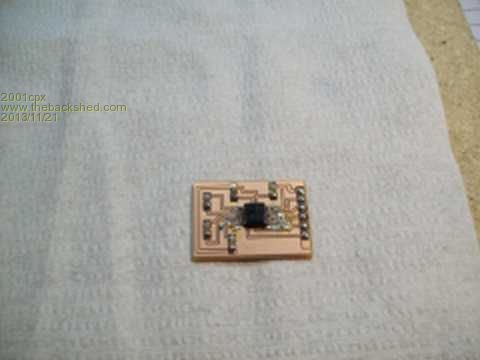
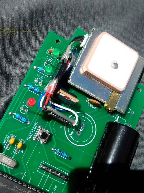
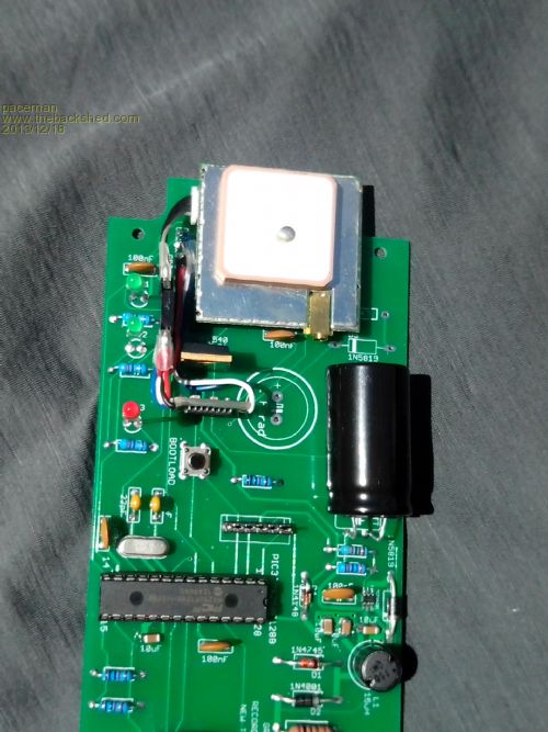
Info for those using the $15 EM408 GPS unit with RS232 output from DX.com. I've just finished building the GPS Tracker from Geoff Graham's article in the Nov 2013 Silicon Chip magazine. I used one of the $1.60, RS232 to TTL converters as per Bob's link above and it's working well. As he notes they're tiny and can fit within a lot of projects. Here's a photo of them. There are 16 pads on these converters but it's not as bad as it sounds. The + and - markings are obviously the power supply (3.0 to 5v) but the supply and ground are all connected to each other so that uses up eight of them. The other pads are the two pairs of RS232 and TTL send/receive connections and are clearly marked on the bottom (cap side). One set of TTL/RS232's I/O's are on the chip (MAX3232) side and the other set are on the bottom. Note that the supply and ground pads are plated through but the I/O pads are not. Here's a photo of the GPS module area of the Tracker with the converter installed. That's it on the other side of the TO220 mosfet - it's smaller than the 5 pin male/female connector I added so that I could remove the GPS module. 
Here's another shot of it. 
For the others who are making this Tracker, note that there's a supply problem with the MicroChip switching power supply chip Geoff designated. There are others that do the job fine though with just the addition of one resistor. Geoff's website here Tracker Project has the details in the FAQ section and he has also written a section here GPS EM 408 about the two versions of the EM 408 GPS module. Greg |
||||