|

|
Forum Index : Windmills : Breaking down a forklift battery bank.
| Author | Message | ||||
wallablack Senior Member Joined: 10/08/2011 Location: AustraliaPosts: 164 |
A theory I had in mind with the finished battery bank was to use a hole saw with a small centre bit. The "hole" part would cut a nice circular post to work with that I could clamp to. Also I might be able to tap into the centre hole which it also produces, but being lead the thread will not be very strong so clamping may be the go. Phill are you saying I can actually feed 20A of wind and 20A of solar into the PL20 by saying "you can feed in 20A of solar as well as control 20A on the load terminal". I understand the wiring side of this but would like to clarify this if possible. The manual doesnt really give to much away for wind but PDF's from the website shows wiring but not the actual A ratings etc. Foolproof systems do not take into account the ingenuity of fools. |
||||
| Warpspeed Guru Joined: 09/08/2007 Location: AustraliaPosts: 4406 |
[quote]A theory I had in mind with the finished battery bank was to use a hole saw with a small centre bit. The "hole" part would cut a nice circular post to work with that I could clamp to.[/quote] That is a great idea. With care in a drill press, with the battery clamped down, you might be able to use a small hole saw without the centre locating drill. It's lead, and if you go slow and very carefully it should cut fairly easily. What if instead of cutting those lead links straight through at 90 degrees, we had instead cut them off at 45 degrees, or a fancy zig zag cut ? That would leave partial ends on each link that project out beyond the sides of the battery case. A simple through hole and a nut/bolt would then be possible. Cheers, Tony. |
||||
wallablack Senior Member Joined: 10/08/2011 Location: AustraliaPosts: 164 |
GOOD idea. I initially thought of just drilling a hole through them so half of the hole would be on one link and half would be on the other link. I would then put a bolt directly through the hole with a washer on each side of the link and clamp it up tight. A big enough bolt would carry enough current but then there would be no give or movement in the terminals etc. Foolproof systems do not take into account the ingenuity of fools. |
||||
| Warpspeed Guru Joined: 09/08/2007 Location: AustraliaPosts: 4406 |
You could still do something like that. Slot some holes with a round file as deep as you dare go. Then bolt some lugs to each terminal, interconnected by a big round wire loop to give it some flexibility. Cheers, Tony. |
||||
fillm Guru Joined: 10/02/2007 Location: AustraliaPosts: 730 |
You might need to read it all again , I never quoted " Feed 20A of wind and 20A of solar into the PL20"... Control the Voltage (by the or with the) L terminal. So the L terminal can "CONTROL" 20A or as I have said previously, switch relays... The PL Sheets will not give Amp ratings as they are generic , you get these from the PL20 / PL40 / PL60 Specs. Download the full PL Series manual and have a good read, there are so many features for correct Battery Management. PhillM ...Oz Wind Engineering..Wind Turbine Kits 500W - 5000W ~ F&P Dual Kits ~ GOE222Blades- Voltage Control Parts ------- Tower kits |
||||
wallablack Senior Member Joined: 10/08/2011 Location: AustraliaPosts: 164 |
Yes I did misread that Phill... I have a copy of the PL Series Reference Manual which is very comprehensive. Such a great controller with so many great functions too. Foolproof systems do not take into account the ingenuity of fools. |
||||
wallablack Senior Member Joined: 10/08/2011 Location: AustraliaPosts: 164 |
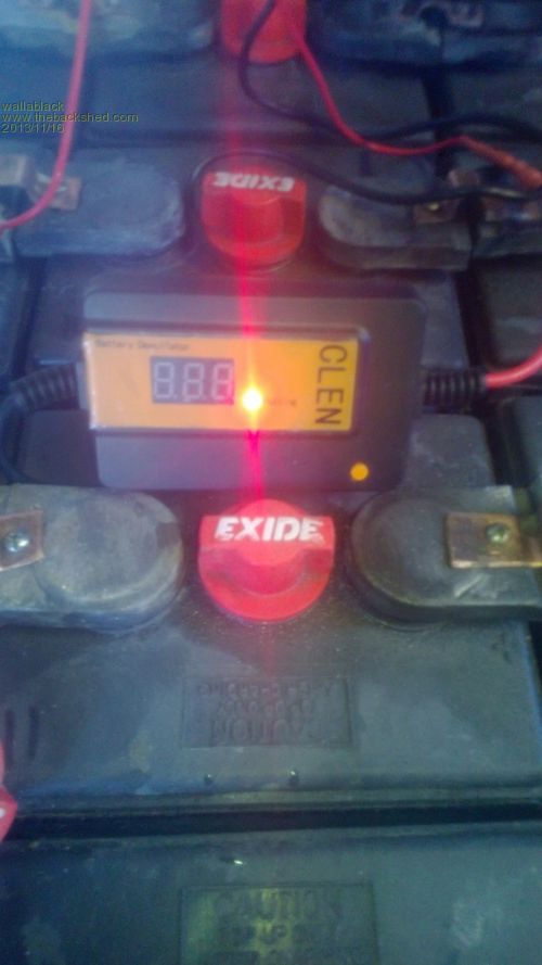
Just wanted to share some pics. Below is the desulfator I purchased in attempt to rejuvenate the old batteries.$30ish from eBay. 
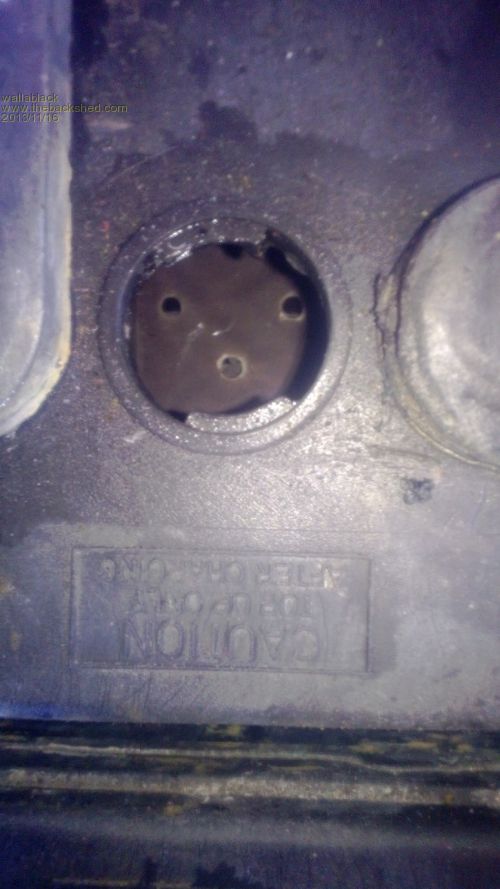
Below is the inside of one of the batteries before I ran the desulfator. 
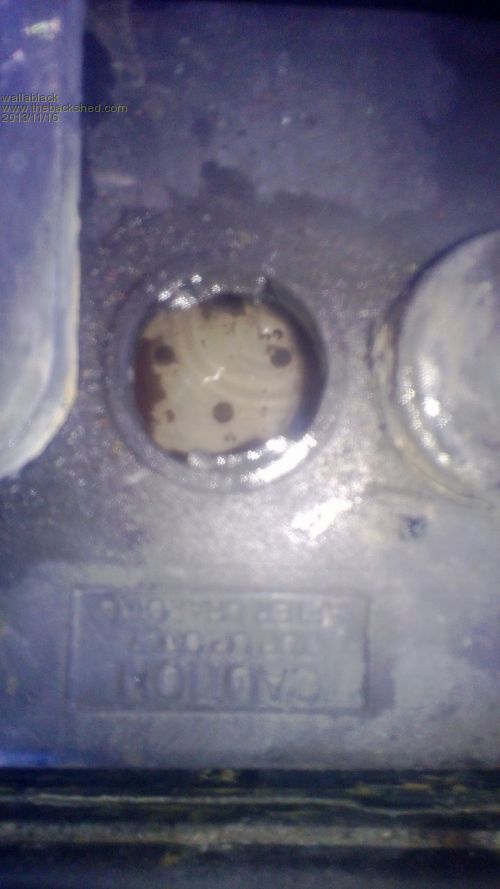
And below is a photo of the same battery after I ran it for a bit over a week. 
I have mixed feelings about whether these things work or not as a lot of people do. The top plate inside the battery has probably cleaned itself through the charging and equalizing process while it was bubbling flat stick. As we can only see the top plate who would know what has happened to the plate below that really count. You can get a sneak peak at the plates through the small holes present and they do seem to be better looking. Just thought I would share. Foolproof systems do not take into account the ingenuity of fools. |
||||
| Warpspeed Guru Joined: 09/08/2007 Location: AustraliaPosts: 4406 |
Sulphation reduces the active plate area and increases the battery internal resistance. Best way to check that is to do a fairly high rate discharge, and measure the terminal voltage with a sudden step change in load. For instance pull 20 Amps for a few minutes to remove the surface charge and let the battery settle down into a steady (fairly high) discharge mode. While monitoring the battery terminal voltage, quickly switch in an extra maybe ten amps of load and measure by how much the terminal voltage falls. Switch out the the extra load, and measure by how much the voltage rises back. Average the two voltage changes. Ohms law will then tell you the battery internal resistance. For instance..... Battery open circuit voltage before test 13.8 volts. Connect up main discharge load, voltage falls to 12.9v and pretty much stabilises after ten minutes discharge. Switch in 8.5 amp extra load, voltage immediately falls to 12.8v Switch out the 8.5 amp load, voltage springs back to original 12.9v Voltage falls by 0.1v with 8.5 amp load. R= E/I Battery internal resistance 0.1/8.5 = .0118 ohms A before and after test will quickly tell you if a sulphated up battery is improving, and by roughly how much. In fact a test like this carried every few months and recording the readings can be quite revealing about general battery health. Cheers, Tony. |
||||
wallablack Senior Member Joined: 10/08/2011 Location: AustraliaPosts: 164 |
Hey thanks Tony, great piece of information. I will try this soon. Foolproof systems do not take into account the ingenuity of fools. |
||||
wallablack Senior Member Joined: 10/08/2011 Location: AustraliaPosts: 164 |
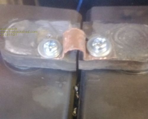
The screws ended up being too small in the end. There is a fair bit of movement with the heat changes and the small screws just weren't enough to keep a good contact between the copper bridges and the lead terminal. I drilled an 8mm hole through the lead connection terminals and put a nut, bolt and washer through the lot and screwed them up really tight...problem solved. 
I have decided to break the bank down to 4 x 12V 415AH banks and work on one at a time. While I am working one one bank the next is already on mains 4A charge so when it comes time to play with these ones some of the work has already been done. Overall the test is working pretty well and the PL20 made the difference I strongly believe. Finding that equalizing at 16V and also being able to Absorb charge for 4 hours(Program 4)then Float at 13.8V. I think previously the charge was just surface charge and being able to hold it at 14V for 4 hours achieved a deeper plate charge changed things. After doing this for a few days I have noticed the charge lost over night with zero load was smaller. Before the addition of the PL20 I was getting losses of over 1.8 - 2.0V down 12V (sometimes 11.8) overnight once the sun had gone. Now the over night loss is smaller and not dropping below 13.2V...might get better with a few more deeper charges. Foolproof systems do not take into account the ingenuity of fools. |
||||