
|

|
Forum Index : Microcontroller and PC projects : Maximite with TFT made simple
| Author | Message | ||||
MicroBlocks Guru Joined: 12/05/2012 Location: ThailandPosts: 2209 |
I like simple solutions. So simple that you have to be brilliant to make them. If you tackle the problem in the right place a lot can be done. Microblocks. Build with logic. |
||||
bigmik Guru Joined: 20/06/2011 Location: AustraliaPosts: 2914 |
Thanks Carsten, As I said, Possibly... Strange the interface changed and a pity really as the blurb says these are a better display with better daylight readability. Regards, Mick Mick's uMite Stuff can be found >>> HERE (Kindly hosted by Dontronics) <<< |
||||
| plasma Guru Joined: 08/04/2012 Location: GermanyPosts: 437 |
nice artikel on heise carsten , iam glad someone make the baby a bit moore popular! |
||||
jman Guru Joined: 12/06/2011 Location: New ZealandPosts: 711 |
Hi Has anybody complied the modified source? If so could you please post the hex file? Almost ready to test just need the hex file and a LED driver Regards John |
||||
jman Guru Joined: 12/06/2011 Location: New ZealandPosts: 711 |
HI "a RC delay (5k variable resistor with 47p to Gnd) has to be inserted between HSYNC out and the 3 framing SS inputs" The 3 framing SS inputs ? I assume these are chip select but I do not see them on the data sheet Carsten could you please post a circuit diagram? Thanks John |
||||
| paceman Guru Joined: 07/10/2011 Location: AustraliaPosts: 1329 |
John, I think Carsten's talking about the CMM pins on the PIC32. Horizontal sync is on Pin 14 and the three framing inputs are on pins 47, 69 and 72. These are all connected together on the CMM so he's looking for a delay between the Hsync pulse out and the three framing pin inputs getting their pulse. Greg |
||||
bigmik Guru Joined: 20/06/2011 Location: AustraliaPosts: 2914 |
Hi All, I think Carsten is doing as I mentioned in this thread (the PDF I uploaded on the first post says it all) TBS Thread Regards, Mick Mick's uMite Stuff can be found >>> HERE (Kindly hosted by Dontronics) <<< |
||||
| paceman Guru Joined: 07/10/2011 Location: AustraliaPosts: 1329 |
Definitely a much better explanation Mick - I remembered your post but was too lazy to look it up! Greg |
||||
jman Guru Joined: 12/06/2011 Location: New ZealandPosts: 711 |
Thanks Mick It know makes sense John |
||||
| bovist Newbie Joined: 21/06/2013 Location: GermanyPosts: 11 |
Hi John, you'll find circuit diagrams and sources on https://github.com/heise/MAXIMITE I made some changes to the values, please not the differences. --------------- Greetings, Carsten Meyer www.keyboardpartner.de |
||||
jman Guru Joined: 12/06/2011 Location: New ZealandPosts: 711 |
Hi I have managed to get my TFT 5" screen to work as it has the same resolution as the 4.3" screen It is connected to a UBW32 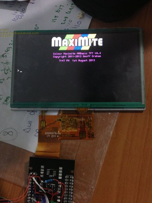
I cannot seem to get the touch to work Looking at the source code I see the following #define TOUCH_OFS_X 63 // on our screen 63, measured by ADC #define TOUCH_MAX_X 955 // on our screen 955, measured by ADC #define TOUCH_OFS_Y 115 // on our screen 115, measured by ADC #define TOUCH_MAX_Y 860 // on our screen 860, measured by ADC Do I need to measure my touch panel as it is 5" not 4.3" and use the measured vaules? If so what would the procedure be to do this ? Any help would be greatly appreciated Thanks John |
||||
| OA47 Guru Joined: 11/04/2012 Location: AustraliaPosts: 926 |
By the jottings behind the TFT it looks like some heavy thinking was required, good work  . Sorry I cannot help with the touchscreen. . Sorry I cannot help with the touchscreen.  |
||||
| Geoffg Guru Joined: 06/06/2011 Location: AustraliaPosts: 3194 |
Carsten's design for the LCD equipped Maximite (called the TFT Maximite) will be published in the German magazine c't along with an article written by me. The magazine is due out in the European fall (ie, in a few months). As part of this effort I have integrated Carsten's changes into the main MMBasic source code tree and produced a beta copy of the firmware. I have been running some tests on an early prototype and it works well including support for the touch sensitive aspects of the screen. If anyone is interested in playing with this version of the firmware send me an email and I will reply with the beta version attached (the more beta testers the better). When the magazine article is published I will make the final version of the firmware and source available on my websites. Geoff Geoff Graham - http://geoffg.net |
||||
jman Guru Joined: 12/06/2011 Location: New ZealandPosts: 711 |
Email sent John |
||||
| Zonker Guru Joined: 18/08/2012 Location: United StatesPosts: 761 |
What types of 5" or 7" LCD displays are able to correctly be connected to the MM's..? |
||||
| Geoffg Guru Joined: 06/06/2011 Location: AustraliaPosts: 3194 |
Carsten's circuit and the future TFT version of MMBasic will work with the Sharp LQ043T3DX02 PSP display (a spare part for the classic Playstation Portable 1000 available on Ebay for about $20) and the newer types of display like the HannStar HSD043I9W1-A, EastRising ER-TFT043-3, TF43014A and the PJ43002A. The video timing for the two types of display is slightly different and you will be able to reconfigure TFT MMBasic for one display or the other with the command CONFIG TFT. Geoff Geoff Graham - http://geoffg.net |
||||
jman Guru Joined: 12/06/2011 Location: New ZealandPosts: 711 |
Hi I have had success with the PSP LSD (Ebay) I have 5" Innolux that has the same resolution model is AT050TN33 this works perfectly. I also opened a cheap 4.3" reverse camera screen the LCD markings are BLC430-16G and this also works perfectly I don't know of any 7" LCD's that the same resolution Hope this helps John |
||||
jman Guru Joined: 12/06/2011 Location: New ZealandPosts: 711 |
40 Pin Connector Adaptor I bought some of these from DX ZIF Adaptor thinking they would make a great cheap adaptor for the FFC connector on the LCD. This turned out to be a much bigger task than I first imagined 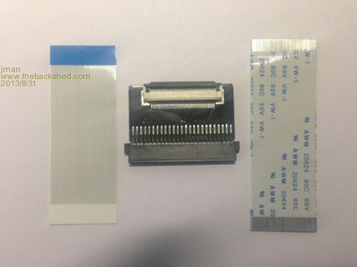
Step 1 Strip the PCB 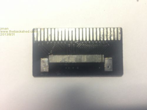
Step 2 Cut the traces under the FFC connector 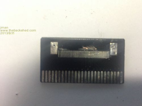
Step 3 Solder the FFC back onto the PCB 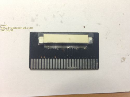
Completed Adaptor Add wires to complete the pins that have no traces and solder the colour pins together on the FFC connector 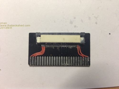
I have since found these on Ebay FFC Adaptor Only thing the edges of the FFC don't seem to have any copper to solder the ends of the FFC connector to ! Hope this helps any others that are looking for cheap FFC adaptor Regards John |
||||
| Zonker Guru Joined: 18/08/2012 Location: United StatesPosts: 761 |
Thanks Jman for the info..! After a quick search, I found the 5" Innolux (AT050TN33) for $27 at mylcdtouchscreen Not sure if you could get a better deal elsewhere.. But the main thing was about the touch panel. I'm not sure if it tested out good or not.. Seems to me that if the screen res for X & Y are the same as the 4.3" displays, the the larger units touch panel should get back the same values in the 5" size... But I know nothing much about any of this..! I was wanting to make a 5" prototype like you did, but was wondering about the results of your testing before ordering them. I would like construct a finished unit with the bigger display, but the 4.3" would be ok also... Looks like making the PCB is going to be a challenge..!! Either way, I think the TFT version of the MM's is a very useful addition of the family and can be used for lot's of different projects.. Awesome work guy's..!! Thanks Jman |
||||
MicroBlocks Guru Joined: 12/05/2012 Location: ThailandPosts: 2209 |
JMan, A touchscreen gives a specific voltage on the x and y axis. Normally you do a calibrate by clicking on some corners of the screen. You would then have for each axis a minimum and maximum voltage. You then divide that range with the amount of pixels. As an example, when you have 1v as a minimum and 4v as a maximum then the range is 3v. With 240 pixels, each pixel would be 0.0125. When you get a 'touch' you read the voltages and substract the minimum voltage from that. If you get 2.5v (a touch around the middle of that axis) then substract 1v = 1.5v. Divide that by 0.0125 and you get 120. There is another way to measure it but that needs more components and a frequency counter. Some microcontrollers have onboard frequency counters that makes it easier. Essentially the touchscreen is a resistor (not the new capacitive ones). If you use that to change the frequency of say a 555 timer and count the frequency you get a pretty accurate position. To see if a screen is 'resistive' or 'capacitive' you can test it by first touching it lightly with the skin of your finger (capacitive) or press with your nail (resistive). Microblocks. Build with logic. |
||||