|

|
Forum Index : Windmills : 12V Dump Load Question.
| Author | Message | ||||
Downwind Guru Joined: 09/09/2009 Location: AustraliaPosts: 2333 |
No probs with putting one across a 24v battery, as long as your wiring can handle 60 amp, i doubt the 3mm wire will handle that, and would have been used at a much higher voltage in the Ups. It dont matter about what is was used for as its just a resistive load and can be fully calculated to the expected result. Pete. Sometimes it just works |
||||
wallablack Senior Member Joined: 10/08/2011 Location: AustraliaPosts: 164 |
Hey Russ, Have a look AT THIS where I was trying to find a suitable big Charge Controller. I have dealt with Hurtle Webster. Bill Walles is the blokes name and he has been building them for years. He builds them in bright red and his were the only ones available in red so they were pretty easy to spot which ones were his. I am telling you now that his work is that highly regarded that there are now others making them in red....sort of like buying a Mitsuboshi (with an o) air conditioner. He will build anything for you but be seated when he gives you the price 'cos you are looking at approx $300 a pop.....and for the hobbyist that's a pretty big outlay....Go with what warpspeed suggested and get a big 'ol load bank. IMO the green one from our overseas friends may be rated at say 300W 0,56ohm but that is mostly at 20 or 40 degrees, somewhere low anyhow....and they don't stay that cool for long...the hotter they get the less efficient they are so really an 'X' rated resistor may not be that at all. So, the expensive HB resistor may be dear but they are truly rated. And yes, they don't stay red for long. They end up looking like a giant turd with two wires coming from it. Foolproof systems do not take into account the ingenuity of fools. |
||||
| Warpspeed Guru Joined: 09/08/2007 Location: AustraliaPosts: 4406 |
It must now be almost thirty years since I ordered resistors of that size from Hurtle Webster, but as I recall resistors of that size were rated at 1000 Watts at 250C temperature rise. They are HUGE, and the largest sized conventional wire wound resistor Hurtle Webster make. These are excellent resistors, and if you have three, you have hit the jackpot. If they are in fact 0.4 ohms, then.... At 14 volts there will be 35 amps and 490 watts giving a temperature rise of 123 degrees above ambient. At that temperature in free air they will go brown and smoke, and smell very hot and not smell very nice at all, but they will work fine (and reliably) at that temperature. But I would not do that... A much better solution would be to enclose each of these resistors in a large diameter concentric metal tube, and fit the biggest 12 volt blower fan you can find to one end. Maybe a car heater fan, something like that. You will then have a really nice 14 volt 40 amp load, assuming the blower draws about five amps. The high airflow will greatly reduce the surface temperature the resistor runs at, and there should then be no smoke or smell, just a lot of very warm air. Cheers, Tony. |
||||
wallablack Senior Member Joined: 10/08/2011 Location: AustraliaPosts: 164 |
A very nice heater for the workshop on these cold wintery months.... Foolproof systems do not take into account the ingenuity of fools. |
||||
| Warpspeed Guru Joined: 09/08/2007 Location: AustraliaPosts: 4406 |
It must now be almost thirty years since I ordered resistors that big from Hurtle Webster, but as I recall resistors of that size were rated at 1,000 Watts at 250C temperature rise. They are HUGE, and the largest sized conventional wire wound ceramic tube resistor Hurtle Webster make. These are superb resistors, and if you have three of them, you have hit the jackpot. If they are 0.4 ohms, then.... At 14 volts there will be 35 amps and 490 watts giving a temperature rise of 123 degrees Celsius above ambient. At that temperature in free air they will go brown and smoke, and smell very hot and not smell very nice at all, but they will work fine (and reliably) at that temperature. But I would not do that... A much better solution would be to enclose each of these resistors in a large diameter concentric metal tube, and fit the biggest 12 volt blower fan you can find to one end. Maybe a car heater fan, something like that. You will then have a really nice 14 volt 40 amp load, assuming the blower draws about five amps. The high airflow will greatly reduce the surface temperature the resistor runs at, and there should then be no smoke or smell, just a lot of very warm air. Cheers, Tony. |
||||
| Wombat Regular Member Joined: 27/05/2011 Location: AustraliaPosts: 72 |
I appreciate the responses guys. Well... I actually have 12 off them, and they do read 0.4 ohms. 
Happy days and a good score. I can feel a dump load coming on. 
Russ  |
||||
| Warpspeed Guru Joined: 09/08/2007 Location: AustraliaPosts: 4406 |
If you have that many, two in series across 14 volts should work well without a fan. Temperature rise will fall from 123 degrees to 31 degrees. Just hot enough to grab a hold of without screaming. You have indeed been blessed. Go out and buy a lottery ticket immediately! Cheers, Tony. |
||||
| Wombat Regular Member Joined: 27/05/2011 Location: AustraliaPosts: 72 |
And pull 17.5A or 245W 
A bit slow, but I get it now... 
If I have 2 in series, 4 x, switchable... That would dump 70A @ 14V to 31 deg, nice. Well, that takes care of a few... 2 in series across a 12v battery should make a good load tester, as if I know how to make one 
Has anyone make one before? Data graphing? Maximite perhaps? Dreaming again... Russ  |
||||
| Warpspeed Guru Joined: 09/08/2007 Location: AustraliaPosts: 4406 |
I made a battery discharge tester once, that I loaned to a friend. It never came back.... Just a big resistor with a low voltage disconnect. The clever thing about it was that it had a current shunt, a voltage controlled oscillator, a long digital frequency divider chain and an electromechanical counter that displayed "amp hours" at the end of the discharge period. The idea behind it was that the frequency coming out of the VCO tracks the discharge current, and as the discharge current slowly falls off over the discharge period, the VCO frequency falls with it. If the discharge current is maybe twenty amps, the electromechanical counter can be made to tick over at exactly twenty counts per hour, or perhaps two hundred counts per hour if you want to register tenths of amp hours. It could be built all electronic, but a mechanical counter is especially good because it stores the final reading mechanically and the whole thing can then turn itself off at the end of the discharge. Some of these mechanical counters also have a reset to zero button. All very handy if you are trying to evaluate a bunch of batteries, or nurse some sick batteries back to health. Cheers, Tony. |
||||
| Wombat Regular Member Joined: 27/05/2011 Location: AustraliaPosts: 72 |
I made a battery discharge tester once, that I loaned to a friend. It never came back....  The main reason I don't like lending things! The main reason I don't like lending things!
And with a 'electromechanical counter'... How interesting 
Sounds like a great project is in the making. 
Russ  |
||||
wallablack Senior Member Joined: 10/08/2011 Location: AustraliaPosts: 164 |
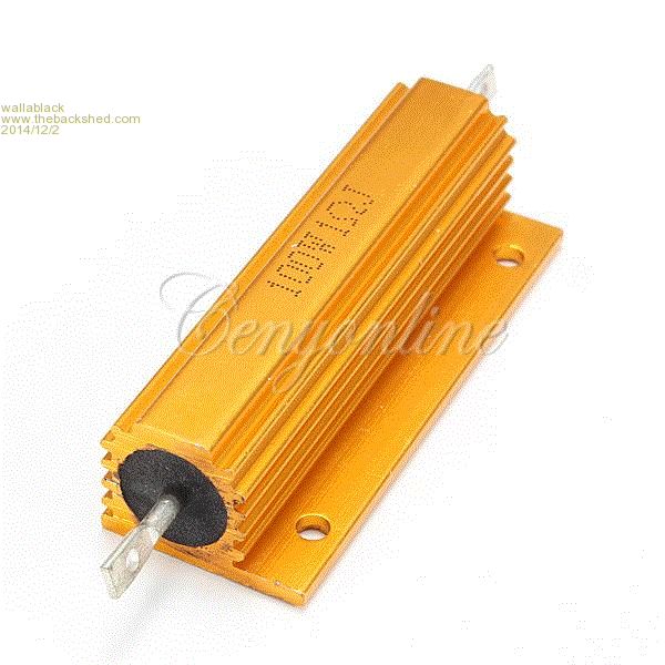
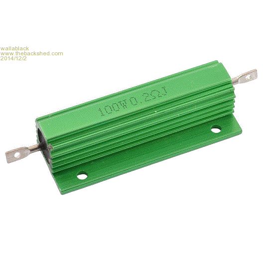
Just working on a couple of little "refurbishments" of a couple of old turbines, one is 12V one is 24V. Found a couple of cheap aluminium clad wire wound like these. 100W 1R for approx. $2.50. Am I correct in saying that I need 5 of these for the 500W 24V? 29V/1R = 29A 500W/29V = 17.2A 17.2/29 = 0.59 (1 Resistor)or x5 to gain 500W 100W 0.2R Am I correct in saying that I need 5 of these for the 500W 12V? 14.4/0.2 = 72A 500/14.4 = 34A 34/72 = 0.47 (1 resistor) or x5 to gain 500W. I think I am confusing myself because something does not seem right... Foolproof systems do not take into account the ingenuity of fools. |
||||
wallablack Senior Member Joined: 10/08/2011 Location: AustraliaPosts: 164 |
Just working on a couple of little "refurbishments" of a couple of old turbines, one is 12V one is 24V. Found a couple of cheap aluminium clad wire wound like these but I think I'm doing something wrong with the calculations. 
100W 1R for approx. $2.50. Am I correct in saying that I need 5 of these for the 500W 24V? 29V/1R = 29A 500W/29V = 17.2A 17.2/29 = 0.59 (1 Resistor)or x5 to gain 500W 
100W 0.2R Am I correct in saying that I need 5 of these for the 500W 12V? 14.4/0.2 = 72A 500/14.4 = 34A 34/72 = 0.47 (1 resistor) or x5 to gain 500W. I think I am confusing myself because something does not seem right... Foolproof systems do not take into account the ingenuity of fools. |
||||
| Don B Senior Member Joined: 27/09/2008 Location: AustraliaPosts: 190 |
Hi Wallablack, The simplest way to avoid confusing yourself is to do the calculations in a logical sequence. If you want to be able to dissipate 500 Watts at 29 Volts (using 29V as you have, rather than 24V), then the current involved will be 500/29, or 17.2A, as you have calculated. To pass 17.2 A with 29 V applied, you need a resistor of 29/17.2 = 1.68 Ohms (pure Ohms law - R = E/I). With 1 Ohm resistors available, you can connect two in series to give 2 Ohms. If, though, you connect two series pairs in parallel, then you get back to only 1 Ohm total, although now with 400 W (max) capability. If you connected 3 one Ohm resistors in series, then the total resistance would be 3 Ohms, and two of these sets of three 1 Ohm resistor strings connected in parallel would have a total resistance of 1.5 Ohms, and a nominal dissipation capacity of 600 Watts. Using the same process on the 12V application, the required resistance value for 34 A at 14.4 Volts (ie 500 Watts) is 14.4/34, or 0.42 Ohms. If you use the proposed 0.2 Ohm resistors, then you would probably need two parallel strings of 4 resistors in series. Each string would have a resistance of 0.8 Ohms and, in parallel, the total resistance would be 0.4 Ohms. As this would take a total of 8 resistors, the maximum theoretical dissipation would be 800 Watts, which would be more than ample. Obviously, you can play with other available resistance values to reduce the number of resistors if you wish, but it is far better to have more dissipation capability than less. Note also that, if you mix resistance values in a string, be careful to check the dissipation of each resistance to ensure that one is not overloaded. I hope that this helps. Don B |
||||
| Tinker Guru Joined: 07/11/2007 Location: AustraliaPosts: 1904 |
And don't forget that these resistors need to be bolted to a substantial heatsink to be able to dissipate their rated power. Also, use heat sink goo under each. Klaus |
||||
fillm Guru Joined: 10/02/2007 Location: AustraliaPosts: 730 |
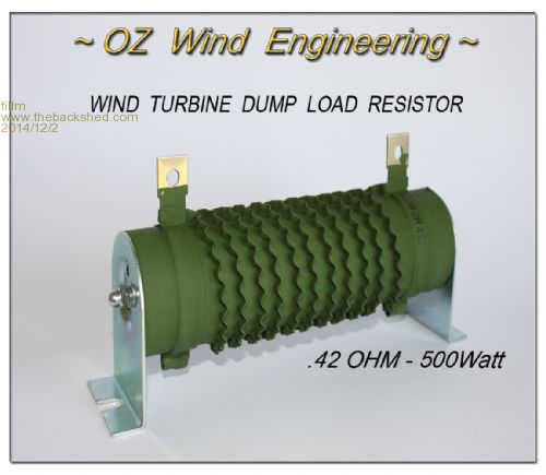
If you want a 500W / .42Ohm that are the built for Wind Turbine diversion loads, I do have them. 
If you do not want to do that way then I think you would be better of making your own -- winding wire around a tile/ fluro tube Encapulated Resistors and many other ways rather than using Audio Resistors. PhillM ...Oz Wind Engineering..Wind Turbine Kits 500W - 5000W ~ F&P Dual Kits ~ GOE222Blades- Voltage Control Parts ------- Tower kits |
||||