
|

|
Forum Index : Windmills : VAWT, F&P, analog MPPT project
| Author | Message | ||||
| Gizmo Admin Group Joined: 05/06/2004 Location: AustraliaPosts: 5078 |
Looking good, keep us posted on how it goes. I like the little terminals 
Glenn The best time to plant a tree was twenty years ago, the second best time is right now. JAQ |
||||
| Warpspeed Guru Joined: 09/08/2007 Location: AustraliaPosts: 4406 |
Building easily replaceable power modules is definitely the way to go with a project like this. Cheers, †Tony. |
||||
| govertical Guru Joined: 11/12/2008 Location: United StatesPosts: 383 |
Hi, the only real difference is the inductor. I am using a 220 uH toroid inductor. This requires a increase in the switching frequency to about 130kHz. If this causes a problem I will have to fabricate some air core inductors so the switching frequency can be reduced. This is the only possible problem I can think of. The isolated power supply should be able to handle the additional gate drivers. It should be easy to make a PCB using my CNC. Once this part of the circuit is working then the micro can be added. just because your a GURU or forum administer does not mean your always correct :) |
||||
| Warpspeed Guru Joined: 09/08/2007 Location: AustraliaPosts: 4406 |
What you will find is that the combination of high switching frequency and high input voltage will substantially increase core losses in those inductors. How hot they get will be the limiting factor. It will be the voltage across the inductor, not the current through it that creates this heating. Cheers, †Tony. |
||||
| govertical Guru Joined: 11/12/2008 Location: United StatesPosts: 383 |
Hi, making progress. I have been able to mill a controller board for the power modules. I still have to populate the board then testing can continue. Thank you for the info. 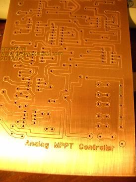
just because your a GURU or forum administer does not mean your always correct :) |
||||
| brucedownunder2 Guru Joined: 14/09/2005 Location: AustraliaPosts: 1548 |
Hi Govertical ,,, Nice looking boards , hope you made a few??. Be interesting to follow your project (maybe I missed a previous chapter) .. Bruce. Bushboy |
||||
| govertical Guru Joined: 11/12/2008 Location: United StatesPosts: 383 |
Hi, I have to verify it works, then I can easily make more. Thanks just because your a GURU or forum administer does not mean your always correct :) |
||||
| govertical Guru Joined: 11/12/2008 Location: United StatesPosts: 383 |
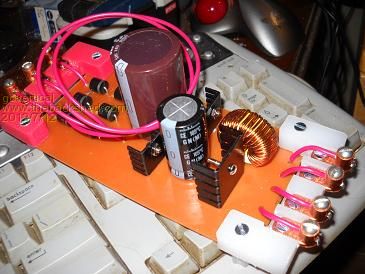
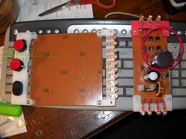
Hi, I fabricated one power module and increase the controller size to a 6 by 6 inch single sided copper clad. Soldering the smaller board was to difficult. Progress is slow but making head way. Cheers 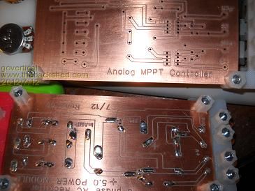
just because your a GURU or forum administer does not mean your always correct :) |
||||
| govertical Guru Joined: 11/12/2008 Location: United StatesPosts: 383 |
Hi, working on controller fabrication. 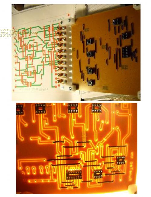
just because your a GURU or forum administer does not mean your always correct :) |
||||
| govertical Guru Joined: 11/12/2008 Location: United StatesPosts: 383 |
Greetings, I found a circuit that may help limit the input voltage. http://www.pssurvival.com/PS/Lightning/Surge_Protections_Cir cuits_2009.pdf Comments welcome. I spent the day increasing the size of jumper pads. I was making to many solder shorts during assembly. 
just because your a GURU or forum administer does not mean your always correct :) |
||||
| govertical Guru Joined: 11/12/2008 Location: United StatesPosts: 383 |
Hi, project update. I installed ICís into controller board and applied power. The board functioned ok. Manual adjust of duty cycle was measured at the output of gate drivers. I have to fabricate more buck power modules. I should be able test with PMA soon. Cheers 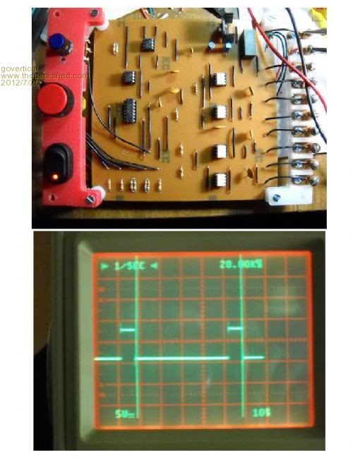
just because your a GURU or forum administer does not mean your always correct :) |
||||
| Warpspeed Guru Joined: 09/08/2007 Location: AustraliaPosts: 4406 |
Great stuff. That nasty ringing you had earlier has completely disappeared. That is a nice solid looking gate drive waveform. Cheers, †Tony. |
||||
| govertical Guru Joined: 11/12/2008 Location: United StatesPosts: 383 |
Hi, when I expand the waveform the ripple is still there. It looks like it is coming from the isolated power supply. I can increase the supply cap on the output of each gate drive or add a filter cap to the output of the isolated power supply or both. Thanks for reminding of the problem. The waveform is just the output of the gate driver, it is not driving the mosfet. 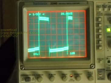
just because your a GURU or forum administer does not mean your always correct :) |
||||
| govertical Guru Joined: 11/12/2008 Location: United StatesPosts: 383 |
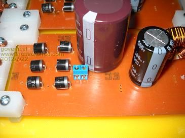
Hi, photos of new proto board layout. I added a terminal for the amp brake out connection on the power modules. The brake out location is for making current measurements at the input and is also the location of the fuse at the input. I still have to add mosfets and diodes. I should able to test in a few days. 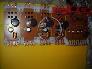
just because your a GURU or forum administer does not mean your always correct :) |
||||
| govertical Guru Joined: 11/12/2008 Location: United StatesPosts: 383 |
Hi,Progress is slow. I still have to route connections. I included standoffs for plexy-glass safety shields. Once a suitable inductor is found the foot print can be reduced. 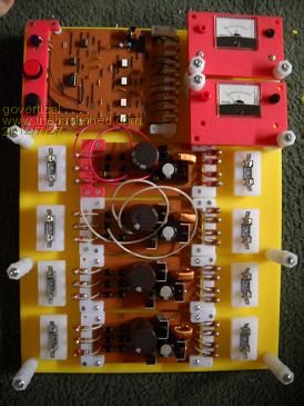 just because your a GURU or forum administer does not mean your always correct :) |
||||
| govertical Guru Joined: 11/12/2008 Location: United StatesPosts: 383 |
Hi, I completed the connections and applied power to the system. I tested the switching signal at each power module. I should be able to test the system with a PMA tomorrow. Cheers 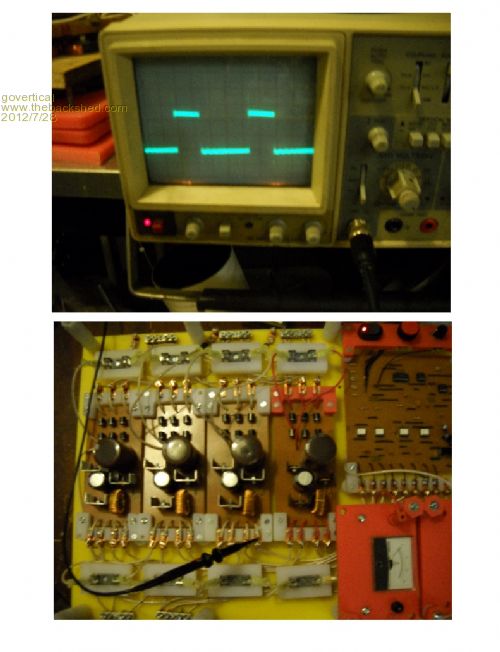
just because your a GURU or forum administer does not mean your always correct :) |
||||
| Warpspeed Guru Joined: 09/08/2007 Location: AustraliaPosts: 4406 |
Great work, keep the info coming. Cheers, †Tony. |
||||
| govertical Guru Joined: 11/12/2008 Location: United StatesPosts: 383 |
Hi, tested system using hand crank on the stock F&P. Three out of the four Buck converters are working. With the duty cycle between 30 and 50 % the input voltage stayed at approximately 40 volts DC. The max output current was about 5 amps at about 12 volts. If the duty cycle was below 30% the input voltage quickly increased above the 400 volt input limit. I stopped spinning the hand crank and avoided damage to the circuit. As I added more buck converter the input voltage remained constant for the same RPM. 12 volt deep cell as test load. I have to trace down the problem with the bad buck converter , fix the F&P to be driven by the drill press and include input voltage limiting circuit. At this time it appears the circuit will work. 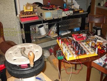
just because your a GURU or forum administer does not mean your always correct :) |
||||
| govertical Guru Joined: 11/12/2008 Location: United StatesPosts: 383 |
Hi, replaced the multi meter measuring the input voltage and the measured values are more realistic. At 20% duty cycle the max input voltage is about 100 volts DC under manual operation of the PMA. just because your a GURU or forum administer does not mean your always correct :) |
||||
| Warpspeed Guru Joined: 09/08/2007 Location: AustraliaPosts: 4406 |
That sounds about right. There will be a direct relationship between duty cycle and input/output voltage, neglecting resistive voltage drops and losses. For 20% duty cycle, theoretical input/output voltage ratio would be 5:1 Cheers, †Tony. |
||||