
|

|
Forum Index : Microcontroller and PC projects : (MM-DM) Maximite RE Controller
| Author | Message | ||||
| cmichaelcouch Newbie Joined: 23/10/2011 Location: United StatesPosts: 16 |
Glenn: I was mainly trying to see what I could use for other projects from this one like schematics for sensor input and the LCD display method. Is that hooked to the VGA or composite? Are most of these LCD composite or VGA? Michael |
||||
| Gizmo Admin Group Joined: 05/06/2004 Location: AustraliaPosts: 5078 |
Thats cool Michael. I've been caught before where I published a circuit built from my collection of junk parts, only to find people have trouble sourcing the same parts and send me emails asking ( sometimes demanding ) for substitutes or if I could redesign the circuit to suit their needs! I dont work that way, this is a hobby, and I will always assume the reader can modify the circuits to suit their own needs or available parts. The little screen is composite video input. Here's a picture of the Alegro current sensor I've mounted ready for use. This one is a 50amp bi-directional type. I've added a 22uF electrolytic ( tantalum would be better ) cap and 10k resistor to smooth out the output, these things have a fast sample speed which is a bit un-desirable for my application. Also added a LED for some "bling". 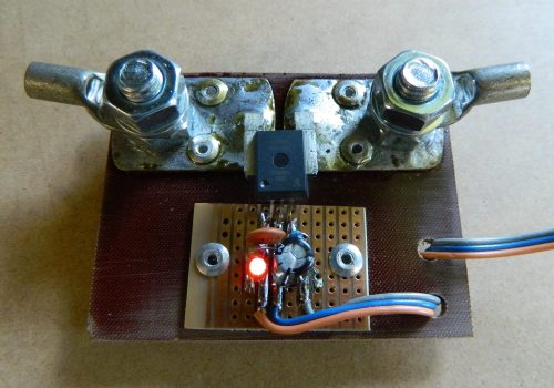
I'm putting together an article on using these Alegro current sensors, with a few tips from other forum members, will put up a post when its done. Glenn The best time to plant a tree was twenty years ago, the second best time is right now. JAQ |
||||
Downwind Guru Joined: 09/09/2009 Location: AustraliaPosts: 2333 |
[quote]these things have a fast sample speed which is a bit un-desirable for my application.[/quote] Change the 22uf cap to 100uf or greater and it will slow down the average of sample rate, this will also give greater stability to the readings to. Althouh i like the sample rate as high as i can get it and prefer to do several readings and add them together. Pete. Sometimes it just works |
||||
| Gizmo Admin Group Joined: 05/06/2004 Location: AustraliaPosts: 5078 |
OK, another update on the RE controller. Its still a long was off from finished, but I though I would post the circuit and code as it is now. The code is a mess, needs to be properly commented and cleaned up. Its not an example of good programming  . Also the logging routines are not in this copy. But it does run, and should display some figures from the floating input pins. If you are interesting in building this thing, better wait until I have finished it. . Also the logging routines are not in this copy. But it does run, and should display some figures from the floating input pins. If you are interesting in building this thing, better wait until I have finished it.
When running, key 0 will bring up the menu screen. From there you can calibrate the readings, set relay voltages, etc. From the main screen you can also press 1,2 or 3 to change the running graph to display readings for every second, minute or hour. The graph is just bling. The main feature of this program is watt hour tracking, so you can see how much power has gone into and out of your battery bank, which it the best way to track its state of charge. Plus the program will control 3 relays to switch in dump loads, etc. The circuit is not showing the battery bank, source, current sensors etc, that will come. The program needs a file called Config.txt, see below. 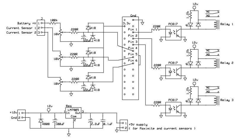
Main Program 10 ' ########################################## 20 ' ## TheBackShed.com 30 ' ########################################## 40 ' 50 ' ########## Read in parameters 60 ' 70 OPEN "Config.txt" FOR input AS #1 80 INPUT #1, VoltMultiplier 90 INPUT #1, AmpInMultiplier 100 INPUT #1, AmpInOffset 110 INPUT #1, AmpOutMultiplier 120 INPUT #1, AmpOutOffset 130 INPUT #1, Output1On 140 INPUT #1, Output1Off 150 INPUT #1, Output2On 160 INPUT #1, Output2Off 170 INPUT #1, Output3On 180 INPUT #1, Output3Off 190 INPUT #1, LowVoltAlarm 200 INPUT #1, ResetWhAtMidnight 210 INPUT #1, LogInterval 220 CLOSE #1 230 DIM WArray(120), WArrayS(120), WArrayM(120), WArrayH(120) 240 ' Reset flags 250 OutPut1State=0 : OutPut2State=0: OutPut3State=0 260 LowVoltAlarmStsate=0 : GraphMode=0 270 WattsHoursIn=0 : WattsHoursOut=0 : WattsPeakIn=0 : WattPeakOut=0 280 DisplayMode=0 : SecCount=0 : CLS 290 SETPIN 1,8 : SETPIN 2,8 : SETPIN 3,8 300 SETPIN 4,1 : SETPIN 5,1 : SETPIN 6,1 310 SETTICK 250, 680 320 PIN(1)=0 : PIN(2)=0 : PIN(3)=0 330 ' 340 ' ########## Set up screen for DisplayMode 1 350 ' 360 LOCATE 170,204 : PRINT "Graphing Seconds"; 370 LOCATE 5,-1 : PRINT "Battery Readings" 380 LOCATE 170,142 : PRINT "Relay 1 Off"; 390 LOCATE 170,154 : PRINT "Relay 2 Off"; 400 LOCATE 170,166 : PRINT "Relay 3 Off"; 410 LOCATE 170,192 : PRINT "Time "; 420 LOCATE 200,-1 : PRINT "Watts In" 430 LOCATE 200,51 : PRINT "Watts Out" 440 LINE (0,105)-(123,215),1,"B" 450 LINE (0,10)-(190,100),1,"BF" : LINE (195,10)-(304,49),1,"BF" : LINE (195,61)-(304,100),1,"BF" 460 FONT #2,1,1 : LOCATE 177,18 : PRINT "V"; : LOCATE 177,60 : PRINT "A"; 470 LOCATE 292,12 : FONT #1,1,1 : PRINT "W"; : LOCATE 292,30 : PRINT "Wh"; 480 LOCATE 292,63 : PRINT "W"; : LOCATE 292,81 : PRINT "Wh"; 490 REM 500 REM ########## Wait for keypress 510 REM 520 k$=INKEY$ 530 IF k$="" THEN GOTO 520 540 IF k$="0" THEN GOTO 2260 550 IF k$="1" THEN 560 LOCATE 170,204 : PRINT "Graphing Seconds"; 570 GraphMode=0 580 ENDIF 590 IF k$="2" THEN 600 LOCATE 170,204 : PRINT "Graphing Minutes"; 610 GraphMode=1 620 ENDIF 630 IF k$="3" THEN 640 LOCATE 170,204 : PRINT "Graphing Hours "; 650 GraphMode=2 660 ENDIF 670 GOTO 520 680 ' 690 ' ########## Main loop, executed every second 700 ' 710 ' ########## Read in values and do maths 720 ' 730 SecCount=SecCount+1 : IF SecCount=4 THEN SecCount=0 740 Volts=PIN(4)*VoltMultiplier 750 AmpsIn=(PIN(5)+AmpInOffset)*AmpInMultiplier 760 AmpsOut=(PIN(6)+AmpOutOffset)*AmpOutMultiplier 770 IF ResetWhAtMidnight=1 AND TIMER<3 THEN 780 WattHoursIn=0 : WattHoursOut=0 790 ENDIF 800 Amps=AmpsIn-AmpsOut 810 WattsIn=Volts*AmpsIn 820 WattsOut=Volts*AmpsOut 830 IF SecCount=0 THEN 840 WattHoursIn=WattHoursIn+(WattsIn/3600) 850 WattHoursOut=WattHoursOut+(WattsOut/3600) 860 ENDIF 870 DisplayVolts$=FORMAT$(Volts,"%.2f") 880 DisplayAmps$=FORMAT$(Amps,"%.2f") 890 DisplayWattsIn$=FORMAT$(WattsIn,"%.1f") 900 DisplayWattsOut$=FORMAT$(WattsOut,"%.1f") 910 DisplayWattHoursIn$=FORMAT$(WattHoursIn,"%.1f") 920 DisplayWattHoursOut$=FORMAT$(WattHoursOut,"%.1f") 930 ' 940 ' ########## Display Data if in DisplayMode 1 950 ' 960 IF DisplayMode=0 THEN 970 FONT #2,2,1 : LOCATE -5,18 : PRINT SPACE$(7-LEN(DisplayVolts$));DisplayVolts$; 980 FONT #2,2,1 : LOCATE -5,60 : PRINT SPACE$(7-LEN(DisplayAmps$));DisplayAmps$; 990 LOCATE 200,12 : FONT #2,1,1 : PRINT SPACE$(7-LEN(DisplayWattsIn$));DisplayWattsIn$; 1000 LOCATE 200,30 : FONT #2,1,1 : PRINT SPACE$(7-LEN(DisplayWattHoursIn$));DisplayWattHoursIn$; 1010 LOCATE 200,63 : FONT #2,1,1 : PRINT SPACE$(7-LEN(DisplayWattsOut$));DisplayWattsOut$; 1020 LOCATE 200,81 : FONT #2,1,1 : PRINT SPACE$(7-LEN(DisplayWattHoursOut$));DisplayWattHoursOut$; 1030 FONT #1 1040 LOCATE 170,105 : PRINT "Net "; INT(WattHoursIn-WattHoursOut); "Wh"; 1050 IF WattsIn>WattsPeakIn THEN 1060 WattsPeakIn=WattsIn 1070 LOCATE 170,117 : PRINT "Peak In "; INT(WattsPeakIn); 1080 LOCATE 250,117 : PRINT " at "; LEFT$(TIME$,5); 1090 ENDIF 1100 IF WattsOut>WattsPeakOut THEN 1110 WattsPeakOut=WattsOut 1120 LOCATE 170,129 : PRINT "Peak Out"; INT(WattsPeakOut); 1130 LOCATE 250,129 : PRINT " at "; LEFT$(TIME$,5); 1140 ENDIF 1150 ' 1160 ' ########## Draw graph if SecCount=0. Basically, run this every second. 1170 ' 1180 IF SecCount=0 THEN 1190 FOR i=1 TO 119 1200 WArrayS(i)=WArrayS(i+1) 1210 NEXT 1220 WArrayS(120)=Volts*Amps 1230 IF RIGHT$(TIME$,2)="00" OR RIGHT$(TIME$,2)="01" THEN 1240 FOR i=1 TO 119 1250 WArrayM(i)=WArrayM(i+1) 1260 NEXT 1270 WArrayM(120)=Volts*Amps 1280 ENDIF 1290 IF MID$(TIME$,4,2)="00" AND (RIGHT$(TIME$,2)="00" OR RIGHT$(TIME$,2)="01") THEN 1300 FOR i=1 TO 119 1310 WArrayH(i)=WArrayH(i+1) 1320 NEXT 1330 WArrayH(120)=Volts*Amps 1340 ENDIF 1350 FONT #1 1360 WMax=0 : WMin=0 1370 IF GraphMode=0 THEN ' #### Copy seconds data into graph array 1380 FOR i=1 TO 120 : WArray(i)=WArrayS(i) : NEXT 1390 ENDIF 1400 IF GraphMode=1 THEN ' #### Copy seconds data into graph array 1410 FOR i=1 TO 120 : WArray(i)=WArrayM(i) : NEXT 1420 ENDIF 1430 IF GraphMode=2 THEN ' #### Copy seconds data into graph array 1440 FOR i=1 TO 120 : WArray(i)=WArrayH(i) : NEXT 1450 ENDIF 1460 FOR i=1 TO 120 1470 IF WArray(i)>WMax THEN WMax=WArray(i) 1480 IF WArray(i)<WMin THEN WMin=WArray(i) 1490 NEXT 1500 IF WMax=0 THEN WMax=0.01 1510 ZeroLine=110+(100/(WMax-WMin)*WMax) 1520 LINE (1,106)-(121,214),0,"BF" : LINE (124,104)-(168,215),0,"BF" 1530 IF WMax>1 THEN LOCATE 125,105 : PRINT INT(WMax); 1540 IF WMin<-1 THEN LOCATE 125,205 : PRINT INT(WMin); 1550 FOR x=0 TO 120 STEP 4 : PSET (x,ZeroLine) : NEXT 1560 LOCATE 125,ZeroLine-5 : PRINT "0"; 1570 IF WMax>WattPeakIn THEN 1580 WattPeakIn=INT(WMax)+1 1590 ENDIF 1600 OldGraphWatts=100/(WMax-WMin)*(WArray(1)) 1610 FOR i=2 TO 120 1620 GraphWatts=100/(WMax-WMin)*(WArray(i)) 1630 LINE (i-1,ZeroLine-OldGraphWatts)-(i,ZeroLine-GraphWatts) 1640 OldGraphWatts=GraphWatts 1650 NEXT 1660 LOCATE 210,192 : PRINT TIME$; 1670 ENDIF 1680 ENDIF 1690 IF DisplayMode=1 THEN 1700 LOCATE 0,30 1710 PRINT FORMAT$(Volts,"%.2f"); "V "; 1720 PRINT FORMAT$(AmpsIn,"%.2f"); "A In "; 1730 PRINT FORMAT$(AmpsOut,"%.2f"); "A Out "; 1740 ENDIF 1750 ' 1760 ' ############ Check for output changes and alarms 1770 ' 1780 IF Volts>OutPut1On AND OutPut1State=0 THEN 1790 OutPut1State=1 1800 PIN(1)=1 1810 IF DisplayMode=0 THEN LOCATE 170,142 ELSE LOCATE 0,42 1820 PRINT "Relay 1 "; : FONT #1,1,1 : PRINT " On "; : FONT #1 1830 ENDIF 1840 IF Volts<OutPut1Off AND OutPut1State=1 THEN 1850 OutPut1State=0 1860 PIN(1)=0 1870 IF DisplayMode=0 THEN LOCATE 170,142 ELSE LOCATE 0,42 1880 PRINT "Relay 1 Off " 1890 ENDIF 1900 IF Volts>OutPut2On AND OutPut2State=0 THEN 1910 OutPut2State=1 1920 PIN(2)=1 1930 IF DisplayMode=0 THEN LOCATE 170,154 ELSE LOCATE 60,42 1940 PRINT "Relay 2 "; : FONT #1,1,1 : PRINT " On "; : FONT #1 1950 ENDIF 1960 IF Volts<OutPut2Off AND OutPut2State=1 THEN 1970 OutPut2State=0 1980 PIN(2)=0 1990 IF DisplayMode=0 THEN LOCATE 170,154 ELSE LOCATE 60,42 2000 PRINT "Relay 2 Off " 2010 ENDIF 2020 IF Volts>OutPut3On AND OutPut3State=0 THEN 2030 OutPut3State=1 2040 PIN(3)=1 2050 IF DisplayMode=0 THEN LOCATE 170,166 ELSE LOCATE 120,42 2060 PRINT "Relay 3 "; : FONT #1,1,1 : PRINT " On "; : FONT #1 2070 ENDIF 2080 IF Volts<OutPut3Off AND OutPut3State=1 THEN 2090 OutPut3State=0 2100 PIN(3)=0 2110 IF DisplayMode=0 THEN LOCATE 170,166 ELSE LOCATE 120,42 2120 PRINT "Relay 3 Off " 2130 ENDIF 2140 IF Volts<LowVoltAlarm AND LowVoltAlarmState=0 THEN 2150 LowVoltAlarmState=1 2160 SOUND 1000,100 2170 IF DisplayMode=0 THEN LOCATE 170,178 ELSE LOCATE 200,42 2180 FONT #1,1,1 : PRINT "Low Volts! "; : FONT #1 2190 ENDIF 2200 IF Volts>LowVoltAlarm AND LowVoltAlarmState=1 THEN 2210 LowVoltAlarmState=0 2220 IF DisplayMode=0 THEN LOCATE 170,178 ELSE LOCATE 200,42 2230 PRINT " " 2240 ENDIF 2250 IRETURN 2260 ' 2270 ' ################# Set up screens 2280 ' 2290 DisplayMode=1 2300 CLS : FONT #2,1,0 : PRINT "Setup" : FONT #1,1,0 2310 LOCATE 0,100 : PRINT "Select which value to change" 2320 LOCATE 0,112 : PRINT "1: Calibrate Readings 6: " 2330 LOCATE 0,124 : PRINT "2: Relay Setup 7: " 2340 LOCATE 0,136 : PRINT "3: Low Volt Alarm 8: Logging interval" 2350 LOCATE 0,148 : PRINT "4: Reset Wh 9: Set time & date" 2360 LOCATE 0,160 : PRINT "5: Wh reset at 00:00?"; ResetWhAtMidnight; " 0: Display Config" 2370 LOCATE 0,172 : PRINT "ENTER: Quit and return to main screen" : PRINT 2380 k$=INKEY$ : IF k$="" THEN GOTO 2380 2390 SETTICK 0, 0 2400 LINE (0,50)-(315,210),0,"BF" : LOCATE 0,60 : PRINT "Readings paused." : PRINT 2410 IF k$="1" THEN 2420 PRINT "Voltage Multiplier. Currently "; VoltMultiplier 2430 INPUT "Change to "; temp$ 2440 IF LEN(temp$)>0 THEN VoltMultiplier=VAL(temp$) 2450 PRINT "Input Current Multiplier. Currently "; AmpInMultiplier 2460 INPUT "Change to "; temp$ 2470 IF LEN(temp$)>0 THEN AmpInMultiplier=VAL(temp$) 2480 PRINT "Input Current Offset. Currently "; AmpInOffset 2490 INPUT "Change to "; temp$ 2500 IF LEN(temp$)>0 THEN AmpInOffset=VAL(temp$) 2510 PRINT "Output Current Multiplier. Currently "; AmpOutMultiplier 2520 INPUT "Change to "; temp$ 2530 IF LEN(temp$)>0 THEN AmpOutMultiplier=VAL(temp$) 2540 PRINT "Output Current Offset. Currently "; AmpOutOffset 2550 INPUT "Change to "; temp$ 2560 IF LEN(temp$)>0 THEN AmpOutOffset=VAL(temp$) 2570 ENDIF 2580 IF k$="4" THEN 2590 PRINT "Are you sure you want to reset the Wh tally?" 2600 INPUT "Enter 1 for Yes, 0 for No "; ResetWattHours$ 2610 IF ResetWattHours$="1" THEN 2620 WattHoursIn=0 : WattHoursOut=0 2630 ENDIF 2640 ENDIF 2650 IF k$="5" THEN 2660 PRINT "Do you want to automatically reset the Wh tally" 2670 PRINT "at midnight? Currently "; ResetWhAtMidnight 2680 INPUT "Enter 1 for Yes, 0 for No "; ResetWhAtMidnight 2690 ENDIF 2700 IF k$="2" THEN 2710 PRINT "NOTE: Off voltage must be higher than On voltage," 2720 PRINT : PRINT "Relay 1 switch On voltage, currently "; Output1On 2730 INPUT "Change to "; temp$ 2740 IF LEN(temp$)>0 THEN Output1On=VAL(temp$) 2750 PRINT "Relay 1 switch Off voltage, currently "; Output1Off 2760 INPUT "Change to "; temp$ 2770 IF LEN(temp$)>0 THEN Output1Off=VAL(temp$) 2780 IF Output1Off<=Output1On THEN 2790 INPUT "Off voltage is less than On voltage! Press ENTER to try again"; temp$ 2800 GOTO 2720 2810 ENDIF 2820 PRINT "Relay 2 switch on voltage, currently "; Output2On 2830 INPUT "Change to "; temp$ 2840 IF LEN(temp$)>0 THEN Output2On=VAL(temp$) 2850 PRINT "Relay 2 switch Off voltage, currently "; Output2Off 2860 INPUT "Change to "; temp$run 2870 IF LEN(temp$)>0 THEN Output2Off=VAL(temp$) 2880 IF Output2Off<=Output2On THEN 2890 INPUT "Off voltage is less than On voltage! Press ENTER to try again"; temp$ 2900 GOTO 2820 2910 ENDIF 2920 PRINT "Relay 3 switch on voltage, currently "; Output3On 2930 INPUT "Change to "; temp$ 2940 IF LEN(temp$)>0 THEN Output3On=VAL(temp$) 2950 PRINT "Relay 3 switch Off voltage, currently "; Output3Off 2960 INPUT "Change to "; temp$run 2970 IF LEN(temp$)>0 THEN Output3Off=VAL(temp$) 2980 IF Output3Off<=Output3On THEN 2990 INPUT "Off voltage is less than On voltage! Press ENTER to try again"; temp$ 3000 GOTO 2920 3010 ENDIF 3020 ENDIF 3030 IF k$="3" THEN 3040 PRINT "Enter the voltage that the Low Battery Alarm" 3050 PRINT "should sound. Currently "; LowVoltAlarm 3060 INPUT "Change to "; temp$ 3070 IF LEN(temp$)>0 THEN LowVoltAlarm=VAL(temp$) 3080 ENDIF 3090 IF k$="8" THEN 3100 PRINT "Log data every 0:never 1:min 2:hour 3:day." 3110 PRINT "Currently "; LogInterval; : INPUT " Change to "; temp$ 3120 IF LEN(temp$)>0 THEN LogInterval=VAL(temp$) 3130 ENDIF 3140 IF k$="9" THEN 3150 PRINT "Currently "; LEFT$(TIME$,5); " "; DATE$ : PRINT 3160 INPUT "Hour"; temp$ : IF LEN(temp$)>0 THEN h$=temp$ ELSE h$=LEFT$(TIME$,2) 3170 INPUT "Minute"; temp$ : IF LEN(temp$)>0 THEN m$=temp$ ELSE m$=MID$(TIME$,4,2) 3180 TIME$=h$ + ":" + m$ 3190 INPUT "Day"; temp$ : IF LEN(temp$)>0 THEN d$=temp$ ELSE d$=LEFT$(DATE$,2) 3200 INPUT "Month"; temp$ : IF LEN(temp$)>0 THEN m$=temp$ ELSE m$=MID$(DATE$,4,2) 3210 INPUT "Year"; temp$ : IF LEN(temp$)>0 THEN y$=temp$ ELSE y$=RIGHT$(DATE$,4) 3220 DATE$=d$ + "-" + m$ + "-" + y$ 3230 ENDIF 3240 IF k$="0" THEN 3250 PRINT "Voltage Multiplier "; VoltMultiplier 3260 PRINT "Input Current Multiplier "; AmpInMultiplier 3270 PRINT "Input Current Offset "; AmpInOffset 3280 PRINT "Output Current Multiplier "; AmpOutMultiplier 3290 PRINT "Output Current Offset "; AmpOutOffset 3300 PRINT "Relay 1 On "; Output1On; ", Off "; Output1Off 3310 PRINT "Relay 2 On "; Output2On; ", Off "; Output2Off 3320 PRINT "Relay 3 On "; Output3On; ", Off "; Output3Off 3330 PRINT "Low volt alarm "; LowVoltAlarm 3340 PRINT "Reset Wh at midnight "; 3350 IF ResetWhAtMidnight=1 THEN PRINT "Yes" ELSE PRINT "No" 3360 PRINT "Logging Interval "; 3370 IF LogInterval=0 THEN PRINT "Never" 3380 IF LogInterval=1 THEN PRINT "1 Minute" 3390 IF LogInterval=2 THEN PRINT "1 Hour" 3400 IF LogInterval=3 THEN PRINT "1 Day" 3410 PRINT "Its a good idea to write these figures down." 3420 INPUT "Press ENTER to return to the menu"; temp$ 3430 ENDIF 3440 OPEN "Config.txt" FOR output AS #1 3450 PRINT #1, VoltMultiplier; ", Voltage Multiplier" 3460 PRINT #1, AmpInMultiplier; ", Amps In Multiplier" 3470 PRINT #1, AmpInOffset; ", Amps In Offset" 3480 PRINT #1, AmpOutMultiplier; ", Amps Out Multiplier" 3490 PRINT #1, AmpOutOffset; ", Amps Out Offset" 3500 PRINT #1, Output1On; ", Relay 1 On voltage" 3510 PRINT #1, Output1Off; ", Relay 1 Off voltage" 3520 PRINT #1, Output2On; ", Relay 2 On voltage" 3530 PRINT #1, Output2Off; ", Relay 2 Off voltage" 3540 PRINT #1, Output3On; ", Relay 3 On voltage" 3550 PRINT #1, Output3Off; ", Relay 3 Off voltage" 3560 PRINT #1, LowVoltAlarm; ", Low Volt Alarm" 3570 PRINT #1, ResetWhAtMidnight; ", Reset Wh at midnight" 3580 PRINT #1, LogInterval; ", Logging Interval, 0:never 1:min 2:hour 3:day." 3590 CLOSE #1 3600 SETTICK 250, 680 3610 IF k$=CHR$(13) THEN GOTO 240 3620 GOTO 2290 Config.txt 34 , Voltage Multiplier 5 , Amps In Multiplier 0 , Amps In Offset 5 , Amps Out Multiplier 0 , Amps Out Offset 50 , Relay 1 On voltage 52 , Relay 1 Off voltage 51 , Relay 2 On voltage 53 , Relay 2 Off voltage 52 , Relay 3 On voltage 54 , Relay 3 Off voltage 48 , Low Volt Alarm 1 , Reset Wh at midnight 0 , Logging Interval, 0:never 1:min 2:hour 3:day. Glenn The best time to plant a tree was twenty years ago, the second best time is right now. JAQ |
||||
| centrex Guru Joined: 13/11/2011 Location: AustraliaPosts: 320 |
Good work Glenn, do you have a screen shot of what it all does. cliff Cliff |
||||
| Gizmo Admin Group Joined: 05/06/2004 Location: AustraliaPosts: 5078 |
Hi Cliff Look at page one of this thread, there's a screenshot there. This will be part of a bigger system when its done, I just wanted to do a update. Glenn The best time to plant a tree was twenty years ago, the second best time is right now. JAQ |
||||
| Gizmo Admin Group Joined: 05/06/2004 Location: AustraliaPosts: 5078 |
Today I went looking for a numeric keyboard. The RE controller will be mounted on a wall, and I didn't want to mount a full sized keyboard on the wall with it, so I planned to use a little numeric keyboard. I've written the software to only need the number keys and ENTER key for all menu operations. I figured any keyboards I find will have a USB connector, so I dug up a green USB to PS2 adapter and tested it on the Duniomite at the heart of my controller, works fine. One thing I did notice, when I plugged in the USB keyboard, the Duinomite reset itself. I'm guessing the USB keyboard and USB to PS2 adapter drew a bit of power when plugged in and this spike in load caused the controller to reset, fair enough. After the reset, it worked perfectly. 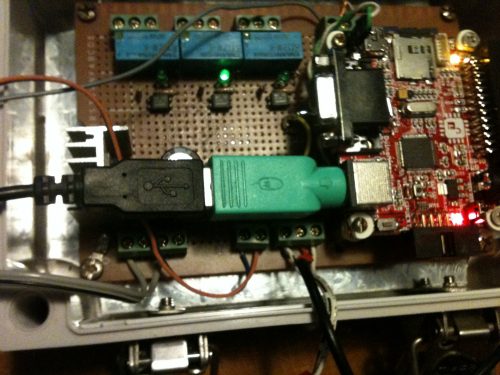
I went for a drive and found this Targus numeric keyboard at a local office supplies store. It cost $32 plus $40 for the bloody parking ticket! Frig me, I was only in there for a couple of minutes! 
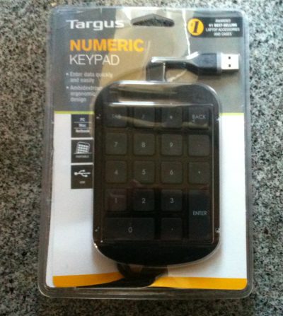
Anyway, moving on. Once home I plugged it into the Duinomite with the green adapter. I doesn't work, dead as a door nail 
So I'll take it back tomorrow and see if I can get my money back. I'll park somewhere else this time. ( $40 for a parking ticket! Thats a joke! It takes a special type of person to be a parking inspector  ) )
I'll have to keep an eye out for a PS2 numeric keyboard, dont want to risk the USB interface not working again. If they dont take this one back, I might hack it open and wire it up to a USB keyboard controller that I've tested, I have a few USB keyboards. While I was at another shop I did noticed these little keyboards. Shame they are Bluetooth, they sure were cute and would go well with a Maximite. 
Glenn The best time to plant a tree was twenty years ago, the second best time is right now. JAQ |
||||
CircuitGizmos Guru Joined: 08/09/2011 Location: United StatesPosts: 1425 |
Glenn: Your adapter might do little more than convert from PS/2 to USB connectors - there are likely just wires inside. If you plug in a USB (only) device, it will not work. The keyboard that you plugged in has a USB plug, but it can auto-detect PS/2 signals and works with the adapter. The keyboard is smart enough to start talking PS/2 (on its own USB lines) when it detects that signalling. The green adapter is nothing more than wires, then. Micromites and Maximites! - Beginning Maximite |
||||
| Gizmo Admin Group Joined: 05/06/2004 Location: AustraliaPosts: 5078 |
Ah, yeah, also just read the post by Don where he cut one up. Is there a PS2 to USB adapter that is actually what it's supposed to be? It wold be nice to keep this little keyboard. Glenn The best time to plant a tree was twenty years ago, the second best time is right now. JAQ |
||||
CircuitGizmos Guru Joined: 08/09/2011 Location: United StatesPosts: 1425 |
Not that I am aware of. The adapter would have to act as a USB host. It takes more silicon and effort to do this. USB is asymmetric - hosts do a lot of work, devices much less. Hosts are expected to have the resources to do this. (The opposite, yes. That would be a device that accepts PS/2 keyboard and is itself a little USB device. Much simpler to implement. I've used those.) Micromites and Maximites! - Beginning Maximite |
||||
bigmik Guru Joined: 20/06/2011 Location: AustraliaPosts: 2914 |
Offerme have this one for $9.95 at the moment Offerme But it is unlikely also to work as a PS2 with the adapter... regards, Mick Mick's uMite Stuff can be found >>> HERE (Kindly hosted by Dontronics) <<< |
||||
| aargee Senior Member Joined: 21/08/2008 Location: AustraliaPosts: 255 |
Glenn, There's some on that hobbyist resource eBay, like this one . Seems to be specifically PS2. - Rob. For crying out loud, all I wanted to do was flash this blasted LED. |
||||
donmck Guru Joined: 09/06/2011 Location: AustraliaPosts: 1313 |
I had a look at dealextreme and ebay. ps2 and numeric keyboard isn't a good match today. I think aargee's find is the best deal for price of the unit and postage. ($12.67AUD) Mind you, a nice little input device for the price, and the app you are wanting to control. BTW, good to see that the little green adapter fits with the VGA plug along side it. We got something right. 
Cheers Don... Edit: A very different one, at a slightly different price: http://www.ioffer.com/i/PS-2-Numeric-Keypad-Numpad-Number-Mi ni-Pad-Keyboard-NEW-189231744 https://www.dontronics.com |
||||
pcaffalldavis Senior Member Joined: 17/10/2011 Location: United StatesPosts: 187 |
Here is a really nice 33 key PS2 numeric pad, waterproof, retractable cable and free shipping from California, yes even to OZ! http://www.ebay.com/itm/33-Key-Mini-Flexible-USB-Keyboard-Nu meric-Keypad-Number-Pad-w-PS-2-Port-Black-/330574296535?pt=P CA_Mice_Trackballs&hash=item4cf7c375d7 Pete in Hyder We're all here 'cause we're not all there. |
||||
| centrex Guru Joined: 13/11/2011 Location: AustraliaPosts: 320 |
Hi Glenn Inspired by your application for the MM, I decided to make an expansion board using your idea for the analogue inputs as well as for the 3 relays except I drive them with a transistor. There are two temp sensor inputs top left digital inputs or out on the top row and a real time clock down the center 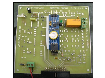
It is a double sided board but I have to solder jumpers through the board. Other than measure the temperature and tell the time and drive the relay I havent done much with it yet. cliff . Cliff |
||||
| Gizmo Admin Group Joined: 05/06/2004 Location: AustraliaPosts: 5078 |
Nice work Cliff, it looks like it will come in handy. Built the current sensor board today. Using a couple of Alegro sensors, one for current in and the other for current out. 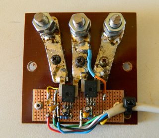
I'm chasing a fault at the moment, only just discoved it and wont get a chance to look into it until later tomorrow. I appear to have some stray voltage on 2 of the input pins. Pin 4 and 5, even with a 5k to ground, measure over 1 volt in both the Maximite software and with a multimeter, when set as analogue inputs. But like I said, I need to look further into it in case I'm doing something really stupid. Glenn The best time to plant a tree was twenty years ago, the second best time is right now. JAQ |
||||
| Gadget Regular Member Joined: 22/06/2011 Location: AustraliaPosts: 70 |
Glenn, apologies if this has been covered already, but the photo of the usb to ps2 converter has a mouse symbol on it so that is why it didnt work, you'll need to chande it for a keyboards specifc unit. green ones are for mouse only they are wiered to different pins on the ps2 side, the purple ones are for keyboards. coded this way to match the sockets on the computer motherboards. any way my 2c worth Terry |
||||
| JohnS Guru Joined: 18/11/2011 Location: United KingdomPosts: 3801 |
Thanks. Seems the sellers regularly don't know or state that! (Some devices don't seem to be marked, though.) John |
||||
| Gizmo Admin Group Joined: 05/06/2004 Location: AustraliaPosts: 5078 |
I've re-started the RE controller from scratch. The Duino-mite based controller is basically finished and works well, but I'm not happy with my interface circuit, so instead of making a new circuit board, I'll keep it to control a windmill at a later time. So its put aside for now. RE Controller version 2. This time I decided to use a CGMMSTICK1, just for fun. The first RE controller used relays on its output, but since then I found a heavy duty N Channel MOSFET output stage from a old UPS, and have decided to drive that directly from the Maximite, via some opto couplers. I only need 3 of each, but I've configured 5 inputs and 5 outputs, for future additions. I also decided to use a current transducer instead of the Alegro current sensor to measure the battery output current. Will post more as it comes together. Glenn The best time to plant a tree was twenty years ago, the second best time is right now. JAQ |
||||
| Gizmo Admin Group Joined: 05/06/2004 Location: AustraliaPosts: 5078 |
Yesterday the 48V to 12V converter arrived. Got no excuses not to finish this thing now. Glenn The best time to plant a tree was twenty years ago, the second best time is right now. JAQ |
||||