|

|
Forum Index : Microcontroller and PC projects : Newbie
| Author | Message | ||||
| Bob Regular Member Joined: 11/08/2011 Location: United KingdomPosts: 41 |
Wow! You did this while I was writing my immediately previous message! Great!!! This is a reasonable solution I think. This, it seems, will also ensure the sequential recognition of interrupts on several pins that occur within a short time. But it still leaves things open to hogging by frequent low-pin-number interrupts, I think, where higher pin-number interrupts may effectively never be honoured. Still a highly worthwhile enhancement, Gerard - thanks. Hopefully Geoff will incorporate your code. We must remember to put the slower interrupting signals on the low-numbered pins, to reduce lockout of faster interrupts; obviously contingent on the relative importance of handling them, but this is always going to be a consideration in a system with relatively slow interrupt servicing of this type. At least "forewarned is forearmed". Bob Bob Dalley http://www.m0rjd.co.uk |
||||
Dinosaur Guru Joined: 12/08/2011 Location: AustraliaPosts: 311 |
Hi all As I haven't come to grips with who is who on this site, so I dont know who is a developer and who is a contributor. Is the code you have developed available for download and capable of updating my unit ? Not that I am desperately waiting for it, but I am developing code to replace old hardware. Just so I understand what you have done. An Int happens on Pin1, and the program gets diverted to the Int routine. Whilst there ,I check if the MM.PCNT variable has a value > 0. If so, my count would be existing count + 1 for this int + value in MM.PCNT.? How many pins can this be used for ? Regards EDIT: As a wishlist, the 100uSec would be adjustable, so I can filter out noise. Regards Hervey Bay Qld. |
||||
| seco61 Senior Member Joined: 15/06/2011 Location: AustraliaPosts: 205 |
Hi. Geoff Graham is the developer of the Maximite and the MMBasic firmware. The rest of us are users and some are also delving into the firmware and alternative hardware. As to the code I have modified, I am more than happy to provide the code and/or a hex file that you can load onto your processor. I tend to pass my modifications on to Geoff to see if he wants to incorporate them in the official version. If yes - well and good. If not, then it is an open source project and we are all welcome to make our own modifications and retrofit them to the official releases. What I have done is placed some code in an existing timer interrupt routine. It is set so that the inserted code will be invoked every 80(ish) uS. The 'ish' part is that there is other code in the interrupt routine that will be invoked depending on pin states, timer counts etc. For each of the available 20 I/O pins, the inserted code checks to see if is set for interrupt on level change (ie SETPIN x,6 or SETPIN x,7). If so, it compares the current value of the pin with the value at the last check. If the appropriate state change has occurred, a count for that pin is incremented. In the separate MMBasic interrupt check routine that is invoked between every executable statement (but not while an MMBasic interrupt routine is being executed) a check is made to see if the pin is set for interrupt on level change. If yes, then the count value for that pin is checked for a non zero value. If the count is non zero, the timer interrupt is disabled, the count is copied to MM.PCNT, the count is cleared and the timer interrupt reenabled. The appropriate MMBasic interrupt routine is then executed. When the routine has completed, the interrupt check routine will be invoked again (we are in between executable statements) and the process repeats. The check always starts at pin 1 and completes at pin 20. So effectively the lower the pin number the higher the priority of its interrupt routine. When the interrupt routine is invoked, the MM.PCNT will always be at least 1, and may be more if multiple level transitions have occurred since the interrupt routine for this pin was last invoked. Regards Gerard (vk3cg/vk3grs) Regards Gerard (vk3cg/vk3grs) |
||||
| Bob Regular Member Joined: 11/08/2011 Location: United KingdomPosts: 41 |
Gerard, you make it sound as if these modifications that you have made are trivial. As an assembler man with scan 'C', I'm not (yet) able to make any real contribution, but I do recognize your awesome competence and capability (I2C addition is another such example, and I am very familiar with the TFTa). I take my hat off to you. Does MM.PCNT distinguish between interrupting pins, or is it just a totaliser for detected interruptable conditions? If it were an array of counts for each pin, we could see loss of an interrupt and maybe act accordingly in the high-level service routine? Regards Bob Bob Dalley http://www.m0rjd.co.uk |
||||
| seco61 Senior Member Joined: 15/06/2011 Location: AustraliaPosts: 205 |
Hi Bob. There is an array of counts, one for each pin. When a MMbasic pin level change interrupt is invoked, the count for that particular pin is copied to MM.PCNT before the interrupt is invoked. Regards Gerard (vk3cg/vk3grs) Regards Gerard (vk3cg/vk3grs) |
||||
| Bob Regular Member Joined: 11/08/2011 Location: United KingdomPosts: 41 |
Understood. That's perfect! Regards, Bob Bob Dalley http://www.m0rjd.co.uk |
||||
| seco61 Senior Member Joined: 15/06/2011 Location: AustraliaPosts: 205 |
Hi. I have posted a copy of the firmware with the modified pin level change interrupt code to my web site: Maximite_PinInt.hex Please test and report back. Regards Gerard (vk3cg/vk3grs) Regards Gerard (vk3cg/vk3grs) |
||||
| Bob Regular Member Joined: 11/08/2011 Location: United KingdomPosts: 41 |
Gerard, I have tested a single pin (PIN 1) interrupting at different rates, using a simple programme with "instant" IRETURN: 10 'test for Gerard's interrupt mods
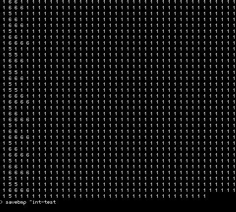
20 SETPIN 1,6,1000 30 PRINT "now we have let rip..." 90 PRINT c; 100 GOTO 90 1000 c = MM.PCNT : IRETURN This shows excellent results at 1kHz rate, the only proviso being that as the screen scroll occurs the counts n MM.PCNT accumulate formidably, but this is only to be expected since the scrolling no doubt takes a good while: 
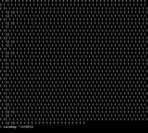
With higher input rates the same thing happens, so at 2kHz we get: 
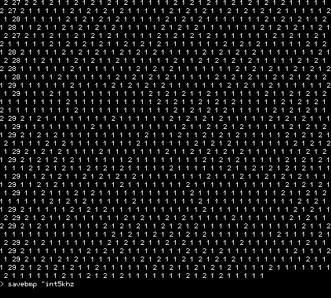
Beyond this rate there are dropped interrupts shown by non-unity count within the display line, as here for 5kHz: 
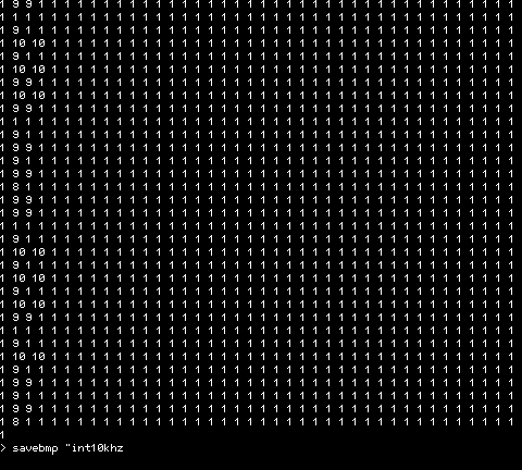
In all the above captures, the counts at the start of each displayed line scale approximately as expected. But beyond this frequency it goes a bit odd. At 10kHz it appears to drop less intra-line edges than it does at 5kHz, which I didn't expect, suggesting it is missing transitions. With a sampling interrupt of 20us I expected it to see both states of the 50us+50us square-wave and differentiate the signal appropriately, but it seems not. With a 50us half-cycle, it should always be sampled in both states by a 20us sample-rate. Does the code perform any filtering such needing 'n' identical samples before acknowledging the new state? This is at 10kHz; at 40us it shows even smaller counts: 
Anyway, operation at 2kHz seems good. Obviously a "real" programme would not normally be scrolling the screen so vigorously - not a lot of point when it is impossible to read it! I haven't yet verified that the summed count of MM.PCNT over a longish period is correct for the input signal, i.e. no missed edges, at lower rates. Regards, Bob Bob Dalley http://www.m0rjd.co.uk |
||||
| Bob Regular Member Joined: 11/08/2011 Location: United KingdomPosts: 41 |
Ah, over a night-time cup of cocoa a possible reason for the strange low-counts at higher input frequencies (10kHz+) slowly lit up my brain... Very slowly! As the input frequency increases, so the simple programme that I used writes values to the screen ever faster. At 10kHz, with 40 single-digit values written, a line of data on the screen takes only 40 x 100us, 4ms, then the screen must scroll (or try to) to display the next line of results. Maybe it can't keep up - it certainly looks pretty excited! I should have limited the programme to output less than a screenful before stopping, and cleared the screen first, so it doesn't scroll. I'll try that tomorrow at the high rates, to see if it is different. Also I'll try simply accumulating the MM.PCNT value for a sensible-ish time (maybe 10s) using a timer interrupt (SETTICK) to define the duration, with not a lot else happening, and report back the results. Now, where did I put that cocoa? Regards, Bob Bob Dalley http://www.m0rjd.co.uk |
||||
Dinosaur Guru Joined: 12/08/2011 Location: AustraliaPosts: 311 |
Hi all Excellent work, my hat off to both of you. You have alrady done all the testing for me. Bob, my only difference will be that I won't write anything to a screen, as it won't be connected in user mode, only in debug mode. You deserve an explanation on what I will use it for. When I computerise concrete plants, the maximum number of liquids is 6. Typically one additive is discharged into the truck, before water is added. Then when the water is finished (or 90% of the total) the aggs and cem go in. Then the last 10% of water goes on top and one or more additves may be started. So at worst case scenario 2 liquids are running at the same time. The water at 25 pulses per litre and the add's at 1 pulse per milli litre. In terms of the 6 liquids, they just have the choice of 4 additives depending on season or concrete. The system has other liquid meters in paralel to the computer which is used to double check the readings and as an upper limit stop. Batching System Regards and many thanks. Regards Hervey Bay Qld. |
||||
| seco61 Senior Member Joined: 15/06/2011 Location: AustraliaPosts: 205 |
Hi Bob. The sample rate is around 80'ish' uS at best case - and will be a bit longer depending on other processing in the Timer interrupt and also higher priority interrupts. So the best case for keeping track of counts would be around 5kHz - above this and you WILL miss transitions. I had a quick look at the code for scrolling the video, and have made a simple change that hopefully will speed it up (taking advantage of the 32 bit data bus of the PIC32). I have updated the Maximite_PinInt.hex file on my web site, so please download again and test. I am also making some changes to the font handling that may also speed up writing characters to the video memory array. I will update the code with this change later today (I hope) - However, I know Geoff is rewriting the font handling code so the changes I make are not likely to be in the official version. Regards Gerard (vk3cg/vk3grs) |
||||
| seco61 Senior Member Joined: 15/06/2011 Location: AustraliaPosts: 205 |
Hi All. I have modified my firmware to update the video character write routine - this again speeds things up a bit. (Maximite_PinInt.hex) As a side effect I have changed the font character set to be somewhat larger - however I have not finished all the font definitions yet. I also added an extra MMBasic command: INVERT x If the value of x is non zero then characters will be written to the screen inverted. To check the state of the video character inversion, the psuedo variable MM.INVERT returns the current state. Bob, I think you will be pleasantly surprised at how much the writing to the video array has improved in speed. Regards Gerard (vk3cg/vk3grs) |
||||
| Bob Regular Member Joined: 11/08/2011 Location: United KingdomPosts: 41 |
Ah, OK Gerard, thanks for correcting my misunderstanding about the sample rate. At 80us then what I am seeing makes perfect sense. I guess that a reasonable 'specification' for minimum high or low level in order to guarantee an input being detected would be something in excess of 100us, so 5kHz for a squarewave as you say (and as it seems to be). For safety, maybe that should be a longer spec period in order to allow higher priority interrupts to get a look in. I guess that for many of us a spec as large as 500us (i.e. 1kHz square-wave) would be perfectly OK. In any case, it is much much better than the original! Regards, Bob Bob Dalley http://www.m0rjd.co.uk |
||||
| curious1 Newbie Joined: 03/07/2011 Location: AustraliaPosts: 9 |
With all this knowledge about basic around this discussion could I slip a question in please? I have a small QBasic program running in a comandprompt window under xp. I reads a multimeter reading and writes it to a file which is closed after every reading. It works fine but will stop at 2400 computer time and hangs. At the moment I set the PC clock to avoid this but if I forget I have wasted a test cycle. Any advice please? |
||||
| Bob Regular Member Joined: 11/08/2011 Location: United KingdomPosts: 41 |
Hi Dinosaur, Thanks for the description of your process. I can appreciate that 'losing' pulses would be a significant problem for your concrete process. For you, one major benefit of Gerard's modification is that, even if an interrupting event (your pulse-per-litre metering device) does not get serviced before the next one occurs, the value of MM.PCNT correctly carries this fact (a value of 2 or more) so that your pulses are not lost forever as with the original firmware. You might not be able to close the valve 'on the nail' but this must be a problem with any software of limited speed. Regards, Bob Bob Dalley http://www.m0rjd.co.uk |
||||
| Gizmo Admin Group Joined: 05/06/2004 Location: AustraliaPosts: 5078 |
I would start a new forum thread for this, its a bit off topic. If you can, post the code, that way we can look to see why it fails at 2400 Glenn The best time to plant a tree was twenty years ago, the second best time is right now. JAQ |
||||
| Bob Regular Member Joined: 11/08/2011 Location: United KingdomPosts: 41 |
Hi Gerard, I'll use your latest code for the checks that I will be doing today. I eventually managed to get the Windows PC behaving enough yesterday to be able to use the Pickit3 to put the new code into the PIC - goodness knows what ills had befallen, but 'rolling back' to before I installed .net etc for the firmware updater seemed to make it work again. That and a lot of bad language! It quite exhausted me <g>. Regards, Bob Bob Dalley http://www.m0rjd.co.uk |
||||
Dinosaur Guru Joined: 12/08/2011 Location: AustraliaPosts: 311 |
Hi all Bob, you hit it right on the head. If it is out of tolerance, and you know about it, you can report an out of tolerance batch. Typically I have an early cutoff that learns from the last event, so it gets closer to the target each time. And the target is the actual target - tolerance. Regards Regards Hervey Bay Qld. |
||||
| Gadget Regular Member Joined: 22/06/2011 Location: AustraliaPosts: 70 |
Gerard, I would love to see your source code for this Terry |
||||
| Bob Regular Member Joined: 11/08/2011 Location: United KingdomPosts: 41 |
I have modified my firmware to update the video character write routine - this again speeds things up a bit. (Maximite_PinInt.hex) As a side effect I have changed the font character set to be somewhat larger - however I have not finished all the font definitions yet. I also added an extra MMBasic command: INVERT x If the value of x is non zero then characters will be written to the screen inverted. To check the state of the video character inversion, the psuedo variable MM.INVERT returns the current state. Bob, I think you will be pleasantly surprised at how much the writing to the video array has improved in speed. Hi Gerard, I'll use your latest code for the checks that I will be doing today. All, The testing is going well now. Gerard's new INVERT 1 command does as advertised and displays black characters on a white cell background, just the job for highlighting. Also the screen write is very much faster! This is the pleasant surprise that Gerard promised :-). I'm now testing the accumulation of interrupt events over a period, a sort of interrupt-driven timer-counter, and comparing it with a real timer-counter! Odd behaviour that I didn't expect is that using SETPIN pin,0 doesn't unconfigure the interrupting, so counts continue to accumulate and the 2nd & subsequent operations give silly numbers. Maybe SETPIN 0,0 would stop it, but for now I have used SETPIN 8 to configure the pin as an output at the end of the measurement, which works well. It might introduce an extra count as it updates pin mode, who knows! Right now it's working properly (!) and the accumulation over 10s corresponds within 1 count with the reading on the real timer-counter, but that's only at 91.2Hz just to see that it works. I'll now run it for a range of input frequencies and post the results and the test-programme later today (UK time, sorry!). Regards, Bob Bob Dalley http://www.m0rjd.co.uk |
||||