
|

|
Forum Index : Windmills : Requesting selecting wire size for stator
| Author | Message | ||||
| Rastus Guru Joined: 29/10/2010 Location: AustraliaPosts: 301 |
Ui Govertical, It looks "the goods",well done so far.You must have been pressed for time to leave the bearing off.Mistakes are easy to make,but fortunately no breaks.Cheers Rastus see Rastus graduate advise generously |
||||
| govertical Guru Joined: 11/12/2008 Location: United StatesPosts: 383 |
I forgot  ... I am reworking the gears. I am mounting the bearings in the gears so the gear posts will be stationary. It should reduce noise and rotate easier. Is there a link that shows the mathematical formulas for VAWTs? ... I am reworking the gears. I am mounting the bearings in the gears so the gear posts will be stationary. It should reduce noise and rotate easier. Is there a link that shows the mathematical formulas for VAWTs? just because your a GURU or forum administer does not mean your always correct :) |
||||
| govertical Guru Joined: 11/12/2008 Location: United StatesPosts: 383 |
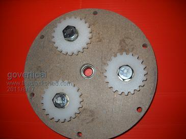
Hi, I am reworking the gear drive. I mounted the bearings in the gears and the gear posts are now stationary. The wobbling planet gears has been resolved and the gear drive should run smoother and make much less noise. 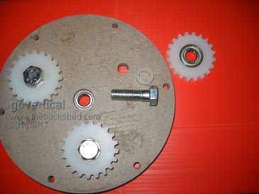
just because your a GURU or forum administer does not mean your always correct :) |
||||
| Rastus Guru Joined: 29/10/2010 Location: AustraliaPosts: 301 |
Hi Govertical, You probably already know gears need "lash"(slight space/gap) between the teeth to run freely.The load is determined by the ratio that is run.I don't know of a chart for VAWT's,other members might help you there.Cheers Rastus see Rastus graduate advise generously |
||||
| govertical Guru Joined: 11/12/2008 Location: United StatesPosts: 383 |
Hi, I had a chance to complete another road today. After alterations the VAWT is spinning more freely. I tried a 3 blade configuration and found that the 6 blade configuration works much better. I am fabricating new blades with a shorter chord and longer length and I am adding a scoop on the leading edge, like a C rotor or a small Lenz scoop. The gear drive when rotating is very quiet until I installs the blades. They are acting as a resonator and amplify the sound, it is a issue that will have to be solved in the future. Telemetry gather from the road test showed lower results, I found a bad connection in the bridge rectifier box and I was only measuring 2 of the phases. Comments welcome and enjoy the day. just because your a GURU or forum administer does not mean your always correct :) |
||||
| Raptor50 Newbie Joined: 17/08/2011 Location: SwedenPosts: 8 |
Nice setup of the PMA.. I am a newbee to this PMA stuff as well, but one thought came to mind though. Would'nt it be better if you put the magnets in different place over eachother to reduce cogging? I think you need just 2 more rectifiers if you do it like that, same regulator i think... Please correct me anyone if i'm wrong.. I wish the day had more hours.. |
||||
| govertical Guru Joined: 11/12/2008 Location: United StatesPosts: 383 |
Hi, on the first page show a diagram of the lines of flux. This is a new idea, an experiment, all the magnet rotors turn together on central shaft, there is no cogging caused by the magnets. The stator coils are all configured as a 3 phase Star. The coils on each stator have to be lined up one above the other so they all experience the same flux pattern at the same time. This allows all the stators to be connected in parallel. This reduces the internal resistance and provides a higher output at a lower RPM. To improve perform I have fabricate thinner stators coils and increase the number of turns for the size magnets I am using. I have ordered the wire and it should be a few weeks for me to complete the work. just because your a GURU or forum administer does not mean your always correct :) |
||||
| govertical Guru Joined: 11/12/2008 Location: United StatesPosts: 383 |
Hi, I started to fabricate scoop blade modification and I realized that if the scoop is mounted on the outside of the blade I will have to redesign the hinge mount because the scoop will prevent the current design from being functional. If the scoop is mounted on the inside the present hinge mount design can be used but then the blades will no longer function as a cross flow turbine configuration, but as a inverted Lenz. I remember reading about other project that tried the scoop on the inside and then outside and it made no difference with the RPMs that were produce. If anyone has any experience with this design please let me know. Scoop inside or outside? Comments welcome. 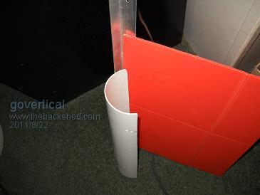
just because your a GURU or forum administer does not mean your always correct :) |
||||
| govertical Guru Joined: 11/12/2008 Location: United StatesPosts: 383 |
http://www.youtube.com/watch?v=AiGD8NQJ3Yc http://www.youtube.com/watch?v=AiGD8NQJ3Yc Hi, after reviewing suggestion and working within fabrication parameters. I am adding 3 blade configuration to inside of turbine. Early observation indicate a increase in RPM. Inner blade set appears to take advantage of inner vortex created by outer 6 blade set. Caps maybe added to inner 3 blade set, but I do have concerns about possible snow building up on the caps during the winter. I have to cut additional hinge assemblies for inner set of blades than I will be ready for another road test. Thank you for the all the suggestion. Comments welcome. just because your a GURU or forum administer does not mean your always correct :) |
||||
| Tinker Guru Joined: 07/11/2007 Location: AustraliaPosts: 1904 |
Interesting solution with these inner 3 blades. Have you tried to rearrange them so they exhaust to the opposite outer blades, the ones going upwind? Kind of like a savonious turbine arrangement where the powered vane exhausts the wind through the center into the downwind vane. Klaus |
||||
| govertical Guru Joined: 11/12/2008 Location: United StatesPosts: 383 |
Hi, I am just exploring different options that is possible using this fabrication methods. I have no training in Aerodynamics. I have been looking at a lot different blade drag configuration. I just wedged some scrape pieces in place and I noticed an improvement in increased RPMs with no load. The air flow off the inner blades is redirected off the center runner into the other blades. I am fabricating the mounting hinges and should be able to do a road test soon. I noticed they offer PVC blades on this site are they flexible? just because your a GURU or forum administer does not mean your always correct :) |
||||
| govertical Guru Joined: 11/12/2008 Location: United StatesPosts: 383 |
http://www.youtube.com/watch?v=ngp5JxV9Vsc&feature=mfu_in_or der&list=UL http://www.youtube.com/watch?v=ngp5JxV9Vsc&feature=mfu_in_or der&list=UL Vortex Power Core, it is easier to say than multi blade savonius with rotating diverter planes. It never to early to start thinking about marketing. It still needs a lot work. Road test in the near future. Enjoy the day. just because your a GURU or forum administer does not mean your always correct :) |
||||
| govertical Guru Joined: 11/12/2008 Location: United StatesPosts: 383 |
Road test results: 6 inner blades with 6 diverting outer blades configuration with 1:3 gear drive. MPH______Amps using 12 volt deep cell as test load 5_________0.0 10________0.03 20________1.3 25________3.0 30________5.5 35________6.5 40________9.0 This is the best road test to date. The gear drive needs improvement and the stators have to be replace. I should have working VAWT up and flying before winter. Comments welcome. 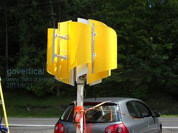
just because your a GURU or forum administer does not mean your always correct :) |
||||
| Rastus Guru Joined: 29/10/2010 Location: AustraliaPosts: 301 |
Hi Govertical, Watching it run is captivating,and the output results look good.On site test will provide real life output for commercial markets,unless they include a car.Cheers Rastus see Rastus graduate advise generously |
||||
| govertical Guru Joined: 11/12/2008 Location: United StatesPosts: 383 |
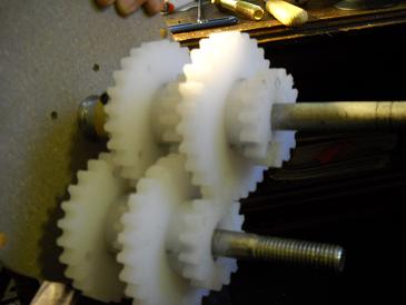
Hi, because of the limited ratio of the planetary gear configuration and the slow but high torque of the blade configuration I am fabricating a 1:15 ratio stacked gear drive. I still have to fit bearings on some of gears and fabricate spacer. At 40 MPH wind speed the blade RPM was approximately 130 without a gear drive. When the new gear drive is install the PMA RPM at 40 MPH will be approximately 1900. Comments welcome. 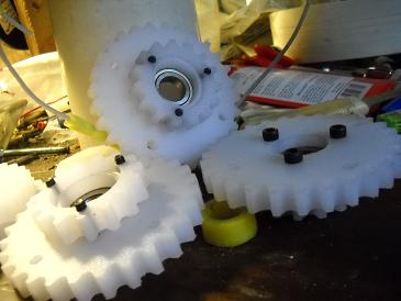
just because your a GURU or forum administer does not mean your always correct :) |
||||
| BobMann Senior Member Joined: 30/06/2011 Location: United StatesPosts: 134 |
Hello I still say you sould try my Mann Smart Drive it will save you a lot of time and head pounding. Here is a vid with it in Irene at 60 MPH+ wind. http://youtu.be/pmDcecB-dQo. I think for you spin any thing a 1900 takes a lot of HP I have spinned my Smart Drives up to 2000 RPM witch is 2000 volts. Your wind look great. Bob Mann |
||||
| govertical Guru Joined: 11/12/2008 Location: United StatesPosts: 383 |
Hi Bob, you are great salesmen.  High volts low amps????? What was the top RPM record during the test? High volts low amps????? What was the top RPM record during the test?
just because your a GURU or forum administer does not mean your always correct :) |
||||
| Rastus Guru Joined: 29/10/2010 Location: AustraliaPosts: 301 |
Hi Govertcal, It's been a long time since I've done gear calculations,however knowing the load and drive in K'watts can help decide how efficient it will be.One to 15 seems a big ask,but you may have the drive torque for it.Heat build up may become a factor for the gear material as well.Cheers Rastus see Rastus graduate advise generously |
||||
| govertical Guru Joined: 11/12/2008 Location: United StatesPosts: 383 |
Hi, thanks for useful information. I never worked with gears before. After looking at the test numbers and considering the wire size used in the stators using a ratio of 1: 15 on the gear drive could result in a stall condition, the stator could burn up, the gears could fail, or all three could be possible. I was going to complete the gear drive to be 1: 15 but it is currently fashioned at 1: 12 which and is good enough for the next road test. The entire project has been designed so that the number of stators can increased or deceased, the gear ratio can be changed, or the blade size can be changed without starting over. I do know that the upper blade RPM is around 100 and the PMA starts producing 5 amps at around 300 RPM. If the gear drive holds up during the next road test I may be able to remove one of stators. I live in a low wind area and the project goal is to have a few small units producing most of the time then have one large unit that only produces some of the time. Thanks again and enjoy the day. just because your a GURU or forum administer does not mean your always correct :) |
||||
| Rastus Guru Joined: 29/10/2010 Location: AustraliaPosts: 301 |
HI Govertical, The optional changes you have available make for an ideal test rig to optmize the best low wind set up and select a larger output unit for those occassions when the "force is with you".All the best Rastus see Rastus graduate advise generously |
||||