| |
  Page 2 of 5 Page 2 of 5   |
| Author |
Message |
KiwiJohn
Guru

Joined: 01/12/2005
Location: New ZealandPosts: 691 |
| Posted: 04:41am 11 Nov 2006 |
 Copy link to clipboard Copy link to clipboard |
 Print this post |
|
Hi guys, I dont really understand what is being proposed but dont overlook that the stator cores are made of laminations for a good reason. |
| |
Megawatt Man

Senior Member

Joined: 03/05/2006
Location: AustraliaPosts: 119 |
| Posted: 05:06am 11 Nov 2006 |
 Copy link to clipboard Copy link to clipboard |
 Print this post |
|
Yes, KiwiJohn, eddy currents could well pose a problem. Depends of course on rotational speed etc. A split in one end would help that, but would probably mean two spots of MIG. What was proposed was an extension to each pole that would effectively make a T out of the pole - I think they are a bit more like an I? The pole pieces would be skewed and almost touching around the circumference, so cogging would be reduced.
Now having proposed this thing, I am throwing everything up in the air in my mind and getting to fundamental issues. What if I'm wrong? I don't think I am, the principle of almost touching pole pieces is almost universal in normal motors and generators and so is skewing where noise is a priority.
There's another thing I need to know about F&P machines, that obviously lots of blokes on this site already know. Are the poles magnetically isolated from one another? Or are the 42 poles perhaps stamped out as a one piece spider?
I have been examing possible reasons for the cogging. With the original rotor/stator combination, there is an exact coincidence of circmferential position between pole and magnets every 4 poles. If you place a new rotor on an old stator, the exact coincidence only occurs every 6 poles. The trouble is though that the coincidence is between like magnetic poles, ie all S or all N. So maybe the cogging is due to the pole span being comparable to the N-S magnet span, so there is a big attraction between an adjacent pair of poles and every stator pole between the magnetic pole pairs?
Megawatt Man |
| |
Highlander

Senior Member

Joined: 03/10/2006
Location: AustraliaPosts: 266 |
| Posted: 05:34am 12 Nov 2006 |
 Copy link to clipboard Copy link to clipboard |
 Print this post |
|
Hi Megawatt, I made a crude jig to cut the plates,(the grinder is on a secure pivot) it looks like crap but actually works well. Does the gap look to big/small?
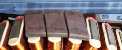
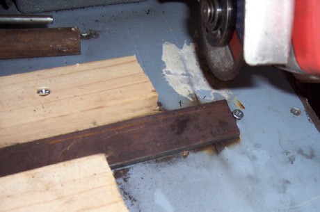
I thought I'd drill a couple of holes in them and mig the buggers on.
Now I'm going to make an ass of myself AGAIN.
I am ignorant of eddy currents, where should this split be?
And what revs will this be a problem without the split?Edited by Highlander 2006-11-13
Central Victorian highlands |
| |
KiwiJohn
Guru

Joined: 01/12/2005
Location: New ZealandPosts: 691 |
| Posted: 08:18am 12 Nov 2006 |
 Copy link to clipboard Copy link to clipboard |
 Print this post |
|
Highlander, eddy currents are electrical currents that get induced in the core material. These are produced the same way as current is induced in the coil windings and that is by being a conductor in the presence of a moving magnetic field. But the real interest about eddy currents is that they heat the metal and hence are a waste of energy. Pretty effective at that they can be too in fact some dynos use eddy current brakes to absorb the power of the vehicle under test (at least I think that is how they work!)
Now, to more practical issues. To be effective we need magnetic lines of flux to connect from the poles of our magnets through one coil then along the stator core a bit and back up through the next coil and so to the pole of the next magnet. Magnetic lines of flux like to flow through iron and suchlike and they dont like air very much. You can see that if your plates had no gaps the flux lines would take the short cut from one magnet to the next and not pass through your coils at all! Putting a gap persuades at least some of the flux lines to take the long way around although some will still go through the air gap.
(P.S. For all you pedants, I understand the traditional models of magnetic lines of flux is being debunked but nonetheless the traditional explanation still works for understanding what must be done to make a magnetic machine function)Edited by KiwiJohn 2006-11-13 |
| |
KiwiJohn
Guru

Joined: 01/12/2005
Location: New ZealandPosts: 691 |
| Posted: 08:30am 12 Nov 2006 |
 Copy link to clipboard Copy link to clipboard |
 Print this post |
|
MegawattMan, I have just sawed up a stator and can confirm that there is metal connecting below the coils so I think you are right that all coils are on one spider.
I think we can read Dr Chalko's paper and draw pointers from it for efficiency. For instance, judging by my exercise cycle test rig the use of capacitors do provide a detectable improvement.
|
| |
Megawatt Man

Senior Member

Joined: 03/05/2006
Location: AustraliaPosts: 119 |
| Posted: 09:39am 12 Nov 2006 |
 Copy link to clipboard Copy link to clipboard |
 Print this post |
|
.G'day Highlander, As KiwiJohn says, eddy currents are one of the causes of losses of energy. Generators only work because as the magnetic field moves past an electrical conducting material,it causes (induces is the tech word) a voltage in the conducting material and that in turn causes an electrical current to flow.
In our alternator, the magnetic field moves past the 42 poes and induces a voltage in them and that causes the electric current to flow out of the machine and into our battery/ heaters/ whatever.
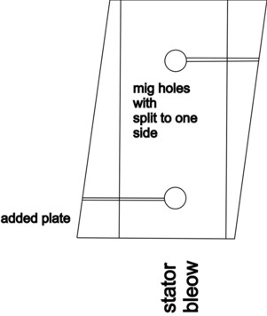
When we dlibeately introduce another piece of electrical conducting material into the region through which the magnet has influence as it swings past, we induce a voltage into it as well as into the coils. This causes an electrial current (called an eddy current) to flow through the introduced material and his results in heating and that amounts to a bit of energy lost that we would have wanted to go into our battery/ whatever. Strategies are adopted to limit the effect of eddy currents. We use many laminations of magnetic materials in machinery to build up to the cross sectional area we need. The laminations are usually coated maybe just with mill scale, but often with another material that effectively provides electrical insulation between the laminations and this reduces the ability of eddy curents to flow. Another strategy is to split any rings of material so the currents cannot flow around the ring. A saw cut would be enough. In our machine, a split anywhere in the ring would do and I would put it between the centre of the pole piece and one of the shortest sides. That might be made easier if your mig hole was in the centre too. Two splits would be even better, one on each side. But that of couse makes it weaker still! Compromise, compromise.
Unfortunateley, the best induction into the pole piece will be close to the point of maximum induction into the coils, so it's a swings and roundabout situation. We will win a bit in the anti-cogging stakes and lose a bit in the eddy current handicap event! Actually, the faster the rotational speed, the higher the induction. I cannot pick it, jut how much the loss will amount to.
About the spacing, yes, I reckon that will do. Compare it to thye width o slots in ordinary electrical machines. They are really only wide enough to get the copper coils down into the widened out coil slots beneath the surface of the rotor or stator that they are installed in.
I have to congratulate you on how far you have ventured and reckon it will be a valuable contribution, no matter how it turns out. All thye best.
And for KiwiJohn, thank you for that investigation. I don't know if you have looked at the circumferential coincidence of magnetic poles and the stator poles carrying the coils. But as I said yesterday, where there is an exact coincidence, the magnets are of the same polarity. It has to be that way of course, so that the voltages in each of the common phase connected arrays are additive. My subconscious has worked on it overnight and I reckon that the magnetic circuit is completed by several of the other poles that are near enough mechanically to the megnetic poles of opposite polarity, via the steel ring that forms part of the spider you have uncovered.
Megawatt Man |
| |
Megawatt Man

Senior Member

Joined: 03/05/2006
Location: AustraliaPosts: 119 |
| Posted: 09:42am 12 Nov 2006 |
 Copy link to clipboard Copy link to clipboard |
 Print this post |
|
Sorry about the typos. I am a Megawtt Man after all, not a competent Secretary!
Megawatt Man |
| |
Pt w/field Matt

Senior Member

Joined: 24/02/2006
Location: AustraliaPosts: 105 |
| Posted: 11:32am 12 Nov 2006 |
 Copy link to clipboard Copy link to clipboard |
 Print this post |
|
hi kiwijohn what size/voltage and type of caps are you using and where in the circuit do they connect?i like to try the setup on my exersize bike
matt down south |
| |
Highlander

Senior Member

Joined: 03/10/2006
Location: AustraliaPosts: 266 |
| Posted: 01:40pm 12 Nov 2006 |
 Copy link to clipboard Copy link to clipboard |
 Print this post |
|
G'day KiwiJohn, thanks again mate, I thought pedants was a typo and you meant to write peasants but I looked it up and it does exist.
Megawatt thanks to you too mate. I had a pretty good idea from school physics how it all worked, just didn't know about old eddy.
I think my drawing is what your saying?
the plate is 3mm thick so it shouldn't bend towards the neo's where the splits are, hopefully.
Wasn't too hard after all.
 Edited by Highlander 2006-11-13 Edited by Highlander 2006-11-13
Central Victorian highlands |
| |
KiwiJohn
Guru

Joined: 01/12/2005
Location: New ZealandPosts: 691 |
| Posted: 06:29pm 12 Nov 2006 |
 Copy link to clipboard Copy link to clipboard |
 Print this post |
|
Hi Matt, I took Chalko's recommendations and put a 1uF between each phase, as they must be non-polarised so do not use electrolytic capacitors. |
| |
Megawatt Man

Senior Member

Joined: 03/05/2006
Location: AustraliaPosts: 119 |
| Posted: 10:16pm 12 Nov 2006 |
 Copy link to clipboard Copy link to clipboard |
 Print this post |
|
Looks good to me. Eddy currents still could be present due to thickness, but at least they won't be able to circulate around the who;e piece. The ideal would be laminated pole pieces, but I don't think that is practical for an add-on pole piece. You've done as much as you can! All the best.
Megawatt Man |
| |
Highlander

Senior Member

Joined: 03/10/2006
Location: AustraliaPosts: 266 |
| Posted: 09:12am 13 Nov 2006 |
 Copy link to clipboard Copy link to clipboard |
 Print this post |
|
Hey Megawatt, thanks for that. You'd be surprised how accurate that jig works, no lasercutting after all 
You said earlier you have never seen a f&p, why not?
This is good fun, even for an clown like me.
If your having trouble getting one let me know.
We can fix that  (email link in profile) (email link in profile)
KiwiJohn, I had a chance to read chalko a few times and he states phase to phase 1uf caps but where do these connect, I'm thinking at the star connections.
A pic would be good  Please. Please.
This of course is another variable so I'll only do it after the "Megawatt T plates" and various neo combinations have been tested.
I have 200 10mm by 10mm 3mm thick magnets if anyone has an idea of how best to space these with the "T plates" let me know. There is actually just enough room for three rows, but the rotor will probably distort.
I have another loopy idea to reinforce it, with a steel band around the rim (largest od), drill some holes and drill into the rotor till you reach the steel inside and couple them together with a bolt/nail and some mig.
Will this help the magnetic field as well?
Probably another stupid question, but does mig welding effect neo's?
Edited by Highlander 2006-11-14
Central Victorian highlands |
| |
dwyer
Guru

Joined: 19/09/2005
Location: AustraliaPosts: 574 |
| Posted: 11:16am 13 Nov 2006 |
 Copy link to clipboard Copy link to clipboard |
 Print this post |
|
Highlander say
Probably another stupid question, but does mig welding effect neo's?
Well it other way around Neo will affect the welding quality and it best way is move magnetic field before using mig welding 
Dwyer the bushman can weld in the outback |
| |
KiwiJohn
Guru

Joined: 01/12/2005
Location: New ZealandPosts: 691 |
| Posted: 05:12pm 13 Nov 2006 |
 Copy link to clipboard Copy link to clipboard |
 Print this post |
|
[quote]KiwiJohn, I had a chance to read chalko a few times and he states phase to phase 1uf caps but where do these connect, I'm thinking at the star connections.
[/quote]
Highlander, the capacitors I got are blobs of brown stuff with two wires. You must have non-polarized ones which means no '-' and '+' ends.
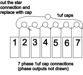
With a star connection, which is what I am doing too, just connect one capacitor between each of the phases. That is one between wire #1 and wire #2, another between #2 and #3 and of course the third one between #3 and #1.
The current in the coils is going back and forth as the magnets pass by but the rectifier diodes do not smoothly switch from one direction to the other which makes the current suddenly stop and start. What we really want is nice smooth sine wave back and forth flow and the capacitors add a degree of 'buffering' to smooth things a bit.
Whatever difference those 'T' plates make I think the effect will be more significant than that of the capacitors!
|
| |
Highlander

Senior Member

Joined: 03/10/2006
Location: AustraliaPosts: 266 |
| Posted: 07:17pm 13 Nov 2006 |
 Copy link to clipboard Copy link to clipboard |
 Print this post |
|
Dwyer, thanks for that, no big deal to take the neo's out.
I only have 1 line in place so far.
I wanted to move them down anyway to fit 3 rows in.
I'll start with the bottom and top rows then if needed a middle one. But it would be best to have the final combination all centred.
KiwiJohn, thanks again. Your a wealth of knowledge, my caps aren't the blob type they're rectangle with no polarity on them.
The small one is 1uf, bigger one is 1.5uf
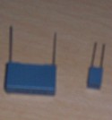
So for 7 phase connection does this drawing look ok?
Central Victorian highlands |
| |
Megawatt Man

Senior Member

Joined: 03/05/2006
Location: AustraliaPosts: 119 |
| Posted: 08:38am 15 Nov 2006 |
 Copy link to clipboard Copy link to clipboard |
 Print this post |
|
G'day Highlander, I'm going to be OK about getting some F&Ps, I have an arrangement with a trade-in picker-upper. Just waiting until he has a couple, then I go for a bit of a drive. Thank you very much for your kind thought about fixing me up with one. Yes that's a 7 phase delta connection. All the best.
Megawatt Man |
| |
RifRaf

Newbie

Joined: 15/10/2006
Location: AustraliaPosts: 32 |
| Posted: 06:39am 16 Nov 2006 |
 Copy link to clipboard Copy link to clipboard |
 Print this post |
|
Hi Guys,
Am keen to see some more actual cogg measurements from people, particularly with the 7 phase stuff but more 3 phase measurments would help as well. |
| |
Highlander

Senior Member

Joined: 03/10/2006
Location: AustraliaPosts: 266 |
| Posted: 07:05am 16 Nov 2006 |
 Copy link to clipboard Copy link to clipboard |
 Print this post |
|
Yeah, sorry RifRaf we got a bit off track there.
How about you Glenn?
That new rotor come yet?
With that cap drawing, I just want to confirm that the caps go in series not paralell.Edited by Highlander 2006-11-17
Central Victorian highlands |
| |
Megawatt Man

Senior Member

Joined: 03/05/2006
Location: AustraliaPosts: 119 |
| Posted: 07:42am 16 Nov 2006 |
 Copy link to clipboard Copy link to clipboard |
 Print this post |
|
Hey, Highlander, yes your drawing of the connections of the caps is right.
Megawatt Man |
| |
Megawatt Man

Senior Member

Joined: 03/05/2006
Location: AustraliaPosts: 119 |
| Posted: 07:44am 16 Nov 2006 |
 Copy link to clipboard Copy link to clipboard |
 Print this post |
|
Hello RifRaf, see posts on the topic "How F&P de-cogged their new rotor" for more on relative performances.
Megawatt Man |
| |
| |
  Page 2 of 5 Page 2 of 5   |

