
|

|
Forum Index : Windmills : The LG Project
| Author | Message | ||||
| VK4AYQ Guru Joined: 02/12/2009 Location: AustraliaPosts: 2539 |
Hi All I did a bit more on the LG today, fitted up a puller to ease the rotor on and of the stator. 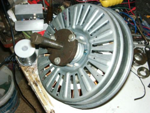
I used a old harmonic balancer puller I had laying around, it made fitting and removing the rotor a breeze, without it I couldn't pull the rotor off by hand as the new magnets where so strong I could only displace the rotor half an inch and then it snapped back into place. It would certainly be a finger snapper if you tried to fit the rotor without the control of the puller 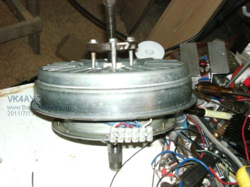
Side view of the rotor and puller and the terminal strip I fitted to terminate the winding ends of the stater. 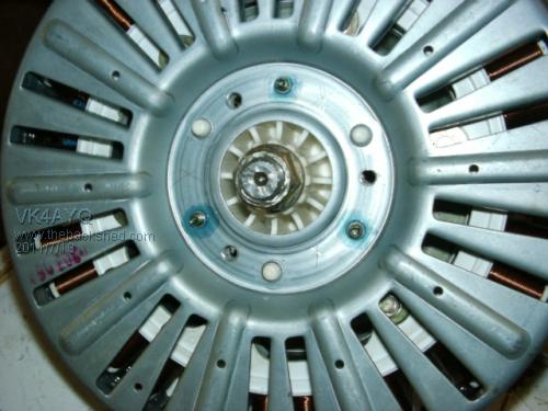
I drilled and tapped three holes into the rotor metal and nylon hub, I used 5/16 UNC bolts to get plenty of thread grip in the nylon. After fitting I found the cogging had increased a lot from the original where it was barely noticeable on this design, it was five or six times as bad. So the rotor was pulled off again and the top of the pole pieces rounded off with the grinder, this reduced the cogging by half but still worse than original, I hope that the 4 meter blade diameter will overcome it, as the monkey said, that remains to be seen. With the old magnets and the original star configuration, a 1/4 turn of the rotor by hand gave 6 volts AC, with the new magnets and connected in delta the same 1/4 turn gave 15 volts AC, not a very definitive test I know, but it looks promising. The windings in star where 11.5 ohms across the star point, each individual winding measured 5.9 ohms and connected in delta the delta points where 2.3 ohms. I shorted the windings together and it was nearly impossible to turn by hand, all I could get was a slow creep turn. If time allows I will set up in the lathe and do some spin testing tomorrow. All the best Bob Foolin Around |
||||
| BobMann Senior Member Joined: 30/06/2011 Location: United StatesPosts: 134 |
Hello to check you cogging take a 1/4 drive tourqe wrench old one with a pointer. put a socket on the shaft and test you will need to get in the 10 to 15 inch pounds for a good break away tests. See you used small round neomagnets so you can not change now. Put Randy showed me a stator that had a twist in it slanted I have tryed it and it works well it will help you very much on the cogging. You can turndown the OD of the stator to if need be. Bob Mann |
||||
| VK4AYQ Guru Joined: 02/12/2009 Location: AustraliaPosts: 2539 |
Hi Bob Will try the tension wrench to check the cogging, I should have slanted the magnets, but I didn't and they are stuck fast now, the rounding of the pole pieces has helped a lot. I like your slanted bar magnets but they where very costly here in Australia, the round ones I had on hand as left over from another project so they got used. Part of the problem is the air gap is only .020" as these magnets are .025 thicker than the original magnets, perfection next week. All the best Bob Foolin Around |
||||
| BobMann Senior Member Joined: 30/06/2011 Location: United StatesPosts: 134 |
This will help from Randy 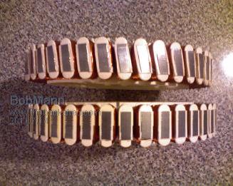
Make a tool out of 2 steel plates weld a nut on each end make it just the right size to slide over the end of the stator but do not hit the wire. insert long bolts and lay into it a little at a time on each pole. You can cut the OD of the stator in you lathe I do it all the time the reshape. i have run the as close as .010 thousend Bob Mann |
||||
MacGyver Guru Joined: 12/05/2009 Location: United StatesPosts: 1329 |
[Quote=BobMann]i have run the as close as .010 thousend If by this you're saying you run an air gap of a tenth (one ten-thousandth) I'd be very careful using that close a tollerance on any wind-driven piece of machinery. A quick yaw at full speed could twist that stator enough to catch it on something running that close and the show would come to a screeching halt. Just an observation; not written in stone, but I'd be really careful with that! . . . . . Mac Nothing difficult is ever easy! Perhaps better stated in the words of Morgan Freeman, "Where there is no struggle, there is no progress!" Copeville, Texas |
||||
| Air Bender Senior Member Joined: 25/01/2011 Location: AustraliaPosts: 206 |
Hi Bob The LG smartdrive looks to have bigger shaft and bearings than the F/P which means we should be able to run a lot larger mill on it. Just out of interst have you ever heard of any boby bending or breaking a F/P shaft im just wondering how much weight they could handle. Keep up the good work Dean. |
||||
fillm Guru Joined: 10/02/2007 Location: AustraliaPosts: 730 |
Dean, The F&P 25mm S/S shaft can take an absolute pounding , some get a bit carried away with oversizing shafts and bearings ,do a couple of quick checks with bearing loading capacities a strengths of solid bar. The Quad stator F&P I built a few years back hit the deck with a very heavy 6 blade prop doing over 700rpm in 60klm+ and didn't even look like bending the shaft SEE HERE but bent and twisted every thing else. I reused the bearing carriers and shafts when I started rebuilding it , but I then scrapped it as the dual stator with twisted poles and cap/dblrs killed it . Everything runs a whole lot better when its all in balance and true. Hey BoB, nice build on the LG , how do you think it is going to go with cogging and increased iorn drag with the small neos. The F&P dual neo rotor I did needed nearly 20klm to get it spinning but I didn't have the ALU GOE222 blades then , hope you have more success . PhillM ...Oz Wind Engineering..Wind Turbine Kits 500W - 5000W ~ F&P Dual Kits ~ GOE222Blades- Voltage Control Parts ------- Tower kits |
||||
| BobMann Senior Member Joined: 30/06/2011 Location: United StatesPosts: 134 |
|
||||
| VK4AYQ Guru Joined: 02/12/2009 Location: AustraliaPosts: 2539 |
Hi All Some pictures of the testing. Initially the test was to determine the Delta voltage of the unit. Then I connected a lead to the windings to do a load test first in delta and later in star. This was in delta at 80 rpm aprox. I hooked up a lead to the dummy load to start testing, couldn't find a politician so I had to use an old heater rated at 2000 watts 240 volt AC it worked OK on DC but was a bit high in resistance to load the alternator properly at low voltages but it was a load. This is the rectifier set up a 100 amp three phase rectifier, that fed through a 10 amp amp meter to an old power point with the heater plugged into it. Note: this is high voltage DC in this circuit and is deadly and will kill as quick as look at you so if you are going to test like this be sure to be careful and keep kids grand kids dogs and maybe wife away from it, only politicians are allowed to touch or grab it. This is delivering 4.5 amps DC @ 415 RPM delta connection. This is the dummy load 2000 watt heater as a substitute for politician, it was happy on DC and it didn't let any smoke out right up to 450 volts DC. Same setup for the star connection as everything was within voltage ratings. Note the higher voltage of the star connection. Just a picture of the windings, you can't see it in the picture but this was after a run of 10 minutes in star at 900 RPM where the windings where to hot to touch and gently smoking. A bit like July Lizzard defending the Carbon Tax. Sorry its a bit blurred but this is the terminal strip where windings can be connected in star or delta. I have some results on a spread sheet and now have to work out how to post that, as when I tried it looked like a dogs breakfast, or parliament question time. All the best Bob Foolin Around |
||||
| vawtwindy Newbie Joined: 23/10/2010 Location: IndiaPosts: 31 |
thats awesome result bob, actually now the gentle smoke is in my ears now. |
||||
mac46 Guru Joined: 07/02/2008 Location: United StatesPosts: 412 |
VK4AYQ, Hello Bob, Very good results as I can see them...just how many amps were produced at 900 rpm/star for that 10 min. run time? I think you could have cooked a "wild turkey" with that much power. Keep you'r fingers out and away from those wires. Good work. With kind regards...Mac46 I'm just a farmer |
||||
fillm Guru Joined: 10/02/2007 Location: AustraliaPosts: 730 |
Bob, What were the voltage and output before with the ceramic magnets compared to what you are getting now , 688W @ 415Rpm in delta? Are you going to attach a set of scales on the torque arm to work out the efficiency / output Vs input which is a true indication of how an alternator is performing. PhillM ...Oz Wind Engineering..Wind Turbine Kits 500W - 5000W ~ F&P Dual Kits ~ GOE222Blades- Voltage Control Parts ------- Tower kits |
||||
| VK4AYQ Guru Joined: 02/12/2009 Location: AustraliaPosts: 2539 |
Hi All It was a interesting exercise but unfortunately When my old lap top died in the storm at xmas time I lost the records that I did on the machine with the original windings and ceramic magnets. From memory though the unloaded ACV in star as tested then where a little lower but not a lot, and the amps was just on 3 amps loaded in star, but considerably lower volts and the windings did not overheat indicating a lot lower overall power. I think that was at 700 rpm as that was the highest usable rpm I could imagine. This time I did go to 900 rpm delta ACV unloaded 385 volts DCV unloaded 450 volts And loaded volts DC 285 volts 7.3 amps. This is really pushing the envelope of the machine but it didn't overheat in delta and didn't appear to be saturated. My next speed up on the lathe is 1200 rpm and sounded ridiculous to try. I will look around for another motor and do a run up on it for comparison in the future. I think they would have a good potential as a dual rotor machine, providing I can harness the high voltage generated in an efficient manner. I have a spare set of magnets so could be worth a try. I have prepared a chart on xl format of the testing and will try to post it this afternoon if I can get it to work. I will set up a scale on the torque arm for power input and cogging when I can get around to it. Just by the feel the cogging is light as I could hold the torque arm wit little pressure on my little finger, and I thing at least half of that was bearing drag as the bearings haven't had a good run to run them in. On the lathe driving it which has a 15 HP motor with idle run current of 4 amps, it went to 7 amps under full load at 900 rpm so around 3 amps, but some of that is I think oil windage in the gearbox due to the high speed. All the best Bob Foolin Around |
||||
| VK4AYQ Guru Joined: 02/12/2009 Location: AustraliaPosts: 2539 |
Hi All Back again, I couldn't get a file to load so scanned and pasted the spreadsheet. From the readings it is apparent that at lower speeds star is a better choice for power output, but it may also be that the load on the alternator was a bit low for delta to load up more in the amps department, when I connect up to the batteries as a low impedance load that will become more apparent. 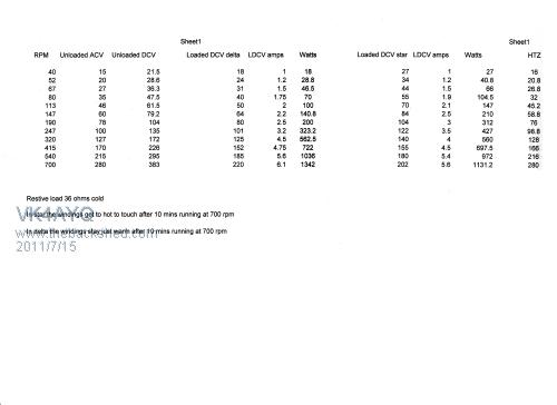
The thing that worries me about star is the Resistance losses in the stater if it did have a over rev for any length of time, In windy conditions it may not get as hot, but the cooling fan built into the rotor does a fairly good job of cooling the stater. Fitting the neos increased the out put by a good 50% but didn't make a lot of difference to the voltage at lower rpm, that was a bit of a disappointment but you can't beat bad luck. All things said it is a good base for a HAWT and is a robust unit with big bearings and shaft that is far stronger that it needs to be for the proposed output. One thing noticeable is how quiet the unit is at low speeds it isn't audible over the noise of the lathe and at high speed it makes a slight whine, but is a bit noisier than the original magnets as it was virtually quiet until the fan noise came in above 500 rpm, if it was up in the wind the wind noise would be louder than the alternator. Maybe it would have slightly better if I put the three magnets per pole instead of two, but I think the limiting factor would be the wire size on the stater as it is only .6MM and according to the wire size chart this is operating on the top end of the wire current carrying capacity. All the best Bob Foolin Around |
||||
| VK4AYQ Guru Joined: 02/12/2009 Location: AustraliaPosts: 2539 |
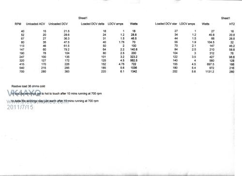
I tried to make the picture bigger as it is hard to read, Sorry it didn't work must be a size limit on the forum. Bob Foolin Around |
||||
| Jarbar Senior Member Joined: 03/02/2008 Location: AustraliaPosts: 224 |
Hi Bob, Seeing the rotor is made of metal,could you not locate a third row of magnets on the outside of the rotor,positioning them over the internal one's.Would the flux not carry through the metal rotor adding to the internally mounted magnets power. Anthony  "Creativity is detirmined by the way you hold your tounge".My Father "Your generation will have to correct the problems made by mine".My Grandfather. |
||||
| VK4AYQ Guru Joined: 02/12/2009 Location: AustraliaPosts: 2539 |
H Anthony There is hardly any flux transfer through the metal of the rotor so would be a waste, I think more magnet strength may also saturate the stater, it will have to do as it is for now, I may try 3 on the next one if I can get another one at a reasonable price. All the best Bob Foolin Around |
||||
| Perry Senior Member Joined: 19/11/2009 Location: Posts: 190 |
I'm jealous of your lathe. That thing is a monster. Reminds me of high school back when they used to have a shop class (when blue collar skills weren't frowned upon like today). They bought the machine tools from a decommissioned battleship. Perry |
||||
| VK4AYQ Guru Joined: 02/12/2009 Location: AustraliaPosts: 2539 |
Hi Perry It is a handy old beast I have had for years, a left over from my engineering works in Victoria. It is a Swiss design machine and much higher quality than the Chinese things that are everywhere now. I just use it for hobby work now so it will outlast me for sure, I have another old lathe that was made in 1885 I have been restoring and it is working now so they do not die easy. When I clean up a bit in the workshop i will post some pictures. All the best Bob Foolin Around |
||||
| VK4AYQ Guru Joined: 02/12/2009 Location: AustraliaPosts: 2539 |
Hi All I did some torque measurements on the LG this morning and here are the results. Delta only tested. 1. 40 rpm 3.00 ft lbs 18 watts Volts: 18 2. 52 rpm 3.40 ft lbs 28.8 watts Volts: 24 3. 67 rpm 4.00 ft lbs 46.5 watts Volts: 31 4. 80 rpm 4.80 ft lbs 70 watts Volts: 40 5. 113 rpm 5.50 ft lbs 100 watts Volts: 50 6. 147 rpm 6.80 ft lbs 140.8 watts Volts: 64 7. 190 rpm 8.00 ft lbs 200 watts Volts: 80 8. 247 rpm 9.80 ft lbs 323.2 watts Volts: 101 9. 320 rpm 12.20 ft lbs 562.5 watts Volts: 125 10. 415 rpm 14.60 ft lbs 722 watts Volts: 152 11. 540 rpm 16.20 ft lbs 1038 watts Volts: 185 12. 700 rpm 17.80 ft lbs 1342 watts Volts: 220 Cogging torque was 1.5 ft lbs 1. .0228 HP Input 2. .0349 HP Input 3. .0510 HP Input 4. .0731 HP Input 5. .1183 HP Input 6. .1903 HP Input 7. .2894 HP Input 8. .4608 HP Input 9. .7433 HP Input 10. 1.1536 HP Input 11. 1.6656 HP Input 12. 3.3724 HP Input Cogging . 0005 HP to overcome It would have been nice to have a more even spread on the rpm readings but that is what the lathe is so am stuck with that, I would have likes to do a reading every 25 rpm but no such luck. I used the kitchen scales to do this so obviously not 100% accurate, but I did try a 3 liter container of water measure and it was spot on 3 KG so that's good enough for me All the best Bob Foolin Around |
||||