| |
  Page 2 of 3 Page 2 of 3   |
| Author |
Message |
Bryan1

Guru

Joined: 22/02/2006
Location: AustraliaPosts: 1344 |
| Posted: 08:06am 27 Jan 2011 |
 Copy link to clipboard Copy link to clipboard |
 Print this post |
|
G'day Shawn,
Glad the mag's got there so quick and with no problems, let me know when you expect to have it all finished and up on the tower as I need need to get off my butt and get that charge controller/ dumpload project under way. I'll be using 4 off 110 amp smd fets which will switch on individually as the input current will be sensed. I'll get the prototype made up and test it to death on my array first to ensure it will handle your new system.
Cheers Bryan |
| |
niall1

Senior Member

Joined: 20/11/2008
Location: IrelandPosts: 331 |
| Posted: 01:15am 28 Jan 2011 |
 Copy link to clipboard Copy link to clipboard |
 Print this post |
|
very clean looking rotors there shawn...can i ask if you got good value from the powder coating people ?....with an open axial i think its money well spent
there much nicer to handle as well....
you could use a simple fridge magnet to double check the index mags when you start on the second disk....if it repels one it should attract the other...then n/s/n/s Edited by niall1 2011-01-29
niall |
| |
shawn

Senior Member

Joined: 30/03/2010
Location: New ZealandPosts: 210 |
| Posted: 08:30am 28 Jan 2011 |
 Copy link to clipboard Copy link to clipboard |
 Print this post |
|
Glen this combined magnet power makes f&p ceramics just plain boring!
Bryan thankyou for all your help and no hurry for that controller i still want one but i am slow at bulding this and even when its first up i will have it shut down when i am not home until all bugs are out and furling spot on! smd?? fets???all gobaly gook to me 
Niall yes the powder coating I think is a must after getting the lazer cutting done and buying this size mags the powder coating was a very small cost much the same as buying good quality paint,But there is a place for building a cheap mill I think the f&p has this covered perfectly, Im trying not to cut any corners with the new mill though.
And yes got the north south thing sorted not the first time though i have one spare magnet to play with already pulled a dent out of my car with it! 
|
| |
frackers

Newbie

Joined: 06/11/2009
Location: New ZealandPosts: 23 |
| Posted: 03:25am 31 Jan 2011 |
 Copy link to clipboard Copy link to clipboard |
 Print this post |
|
Good to see some pictures of the mill Shawn - now I understand all that you told me about on Thursday 
Magnet rotors are in for powder coating, should be back by the end of the week. Back to carving blades again tonight.
For those who have forgotten me (I don't appear on this board very often!!), I'm just down the road from Shawn and may have been his inspiration. That was until just before Christmas when we had a bit of excess wind...

Still, the rebuild is going on apace 
Robin down under - or are you up over |
| |
shawn

Senior Member

Joined: 30/03/2010
Location: New ZealandPosts: 210 |
| Posted: 07:41am 31 Jan 2011 |
 Copy link to clipboard Copy link to clipboard |
 Print this post |
|
Welcome back Robin, yes once i became interested in windmills i looked at all the mills i could see from the road (as im sure everyone has done ) and your mill ran smoother and was going by far the best of them all so top marks  
But you will have made some here curios im sure so you must tell more about your mill do not leave out the recorded amount of power made before the high wind.
shawn |
| |
niall1

Senior Member

Joined: 20/11/2008
Location: IrelandPosts: 331 |
| Posted: 06:57pm 31 Jan 2011 |
 Copy link to clipboard Copy link to clipboard |
 Print this post |
|
i wonder if theres a potential weak spot where the copper wires exit the stator...
where the wire leaves the resin its tightly locked ,but the external tail is free..
it (seems) if a tail is wiggled to much due to connections or strain ..its very easy to break it off
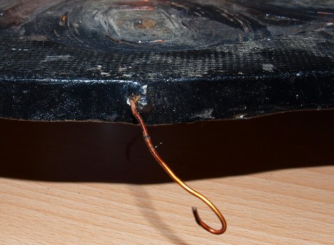
ugly stator with a broken wire because of too much fiddling wireing up the coils in series ...
i only noticed now after taking the pic that the enamel on the existing wire has now also left the crime scene at its exit point for some reason...not a good result here on an open axial
Edited by niall1 2011-02-02
niall |
| |
AMACK
Senior Member

Joined: 31/05/2009
Location: AustraliaPosts: 184 |
| Posted: 02:15am 01 Feb 2011 |
 Copy link to clipboard Copy link to clipboard |
 Print this post |
|
Hi all,
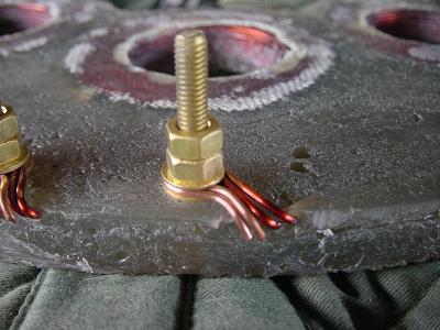
I am no expert on axial flux mills by any means. Just an idear of putting a brass terminal moulded into the resin with a screw on both ends one to hold the copper wire from the stator the other to connect onto. I know from reading other posts that there should not be any metalic material around it but will brass have the same effect?
It could be fixed into the mould before the resin is used and a long thread screw used to hold it in place. That way if the wire broke it could be repaire with cutting the mould. This would also take the risk of coil wire damage away.
Amack
*Note to self
1. Make it thick
2.Make it heavy.
3.Make it stronger than it should be.
4. Don't rush the first job as the second job will cost more and take mor |
| |
niall1

Senior Member

Joined: 20/11/2008
Location: IrelandPosts: 331 |
| Posted: 03:17am 01 Feb 2011 |
 Copy link to clipboard Copy link to clipboard |
 Print this post |
|
its hard to know.....if the stator is clean and without any release compound left on it maybe putting some silicon and cable sleeving around the exit wires might help absorb any vibration and protect from the elements ....it should stick well to the stator but what should be and is and are two different things .....if it doesent stick its a waste of time and could be counter productive ...
its not like we,re putting you under any pressure Shawn ...
incast studs do seem a good idea.... Edited by niall1 2011-02-02
niall |
| |
shawn

Senior Member

Joined: 30/03/2010
Location: New ZealandPosts: 210 |
| Posted: 03:38am 01 Feb 2011 |
 Copy link to clipboard Copy link to clipboard |
 Print this post |
|
Good point amack and niall these are the sort of points I want here, better to talk now than use short four letter words latter when it goes wrong.
I also am not happy with my stattor for other reasons but decided to use it to start cos after testing in real life I may want to add or takeaway a coil or to.
I used a brass bolt that I put on after coming out of the mold this way all connections will not wiggle the week point.
the next stattor will have this silversolded first and all connections inside hard solderd just to be sure.
|
| |
Bryan1

Guru

Joined: 22/02/2006
Location: AustraliaPosts: 1344 |
| Posted: 08:40am 01 Feb 2011 |
 Copy link to clipboard Copy link to clipboard |
 Print this post |
|
G'day Shawn,
With that present connection how about using some long nose pliers then twist the wire into a loop so it will go over the bolt. Now after you twist it put some vise grips on lightly at the base then silver solder the twist. The vise grips will serve as a good heat sink and by using a small sharp flame from a oxy torch it will be a 30 second job and it will ensure the joint will be good for long term use. Now once everything is done and tightened get some 2 part 'needit' epoxy putty to seal and strengthen where the wires exit the stator and provide good weather protection.
Cheers Bryan
|
| |
shawn

Senior Member

Joined: 30/03/2010
Location: New ZealandPosts: 210 |
| Posted: 12:26pm 13 Jul 2011 |
 Copy link to clipboard Copy link to clipboard |
 Print this post |
|
Time I got off my butt and finished this mill!!
so to revive my own old thread here is some pics
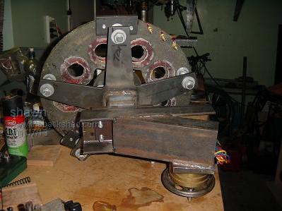
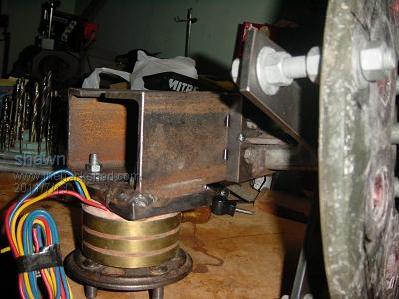
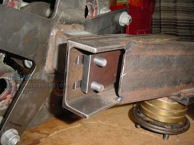
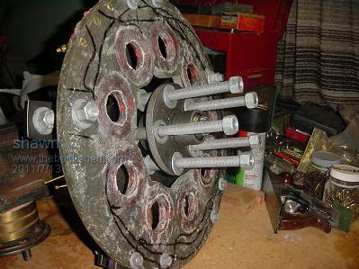
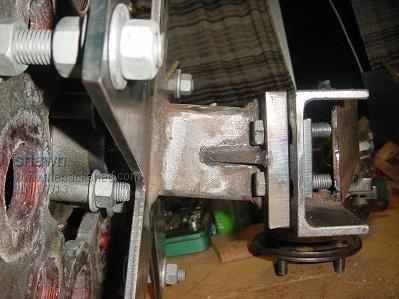
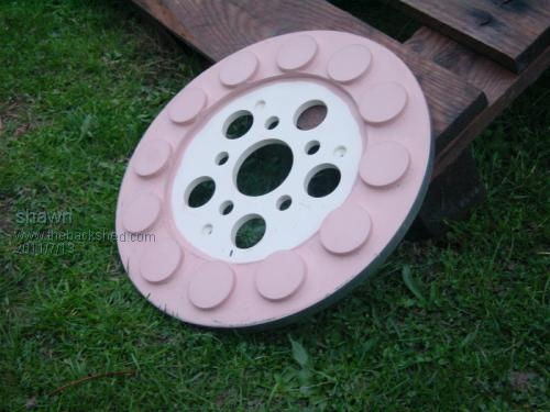
You will notice the adjustable mast offset and sliprings.
Have not put tail hinge on yet I have to do some more homwork on angles???
|
| |
niall1

Senior Member

Joined: 20/11/2008
Location: IrelandPosts: 331 |
| Posted: 12:48pm 13 Jul 2011 |
 Copy link to clipboard Copy link to clipboard |
 Print this post |
|
looking good !..nice bit of Strategic drilling on the stator
those mags are worth a small fortune now ...
the adjustable offset is going to be a big help ...
just a thought ...on the final assembly maybe put some thread lock on the stator nuts ...even lock nuts can come loose ,thread lock is really good for the job especially with nylock nuts
every time i see that rotor i cant help thinking about a sweet shop ...must be the colors ...Edited by niall1 2011-07-15
niall |
| |
shawn

Senior Member

Joined: 30/03/2010
Location: New ZealandPosts: 210 |
| Posted: 07:50am 16 Jul 2011 |
 Copy link to clipboard Copy link to clipboard |
 Print this post |
|
Yes Niall i will take your advice with the thread lock on final assembly!
I did paint the mag plates again, now they are red so no sweets!
Put mill together on bench to cheak cutin rpm and i get 25 volts at 130 rpm i understand matching the load is all important and thought around 100 rpm would be right maby a cap doubler will help with the low end?  
the magnet gap is 20mm with a 16mm stattor.
remember i have built 4 meter diameter blades for this mill
|
| |
VK4AYQ
Guru

Joined: 02/12/2009
Location: AustraliaPosts: 2539 |
| Posted: 12:32am 17 Jul 2011 |
 Copy link to clipboard Copy link to clipboard |
 Print this post |
|
Hi Shawn
Sounds very promising, I like the 25 volts at 130 rpm.
All the best
Bob
Foolin Around |
| |
shawn

Senior Member

Joined: 30/03/2010
Location: New ZealandPosts: 210 |
| Posted: 12:10pm 04 Aug 2011 |
 Copy link to clipboard Copy link to clipboard |
 Print this post |
|
And yes if I ever make another stattor I will make my birdsnest of wires better organised so I don't need fancy drilling and extra hunks of steel were they don't need to be 
But to put me in a better mood I found a telyscopic lattice tower I only get half, the bottom 3 sections each 6 meters long and big/strong enough for a 20 footer the best part is i bought it for the scrap steel price 
Not sure yet but I think i will weld it together and tilt it up the standard way with a gin pole.
unfortunatly the local powers to be will only let me go 12m high including the mill prop.
I have had the local digger in and dug 4 holes for the guys so now just need to find some guy wires and cement.
Its getting close to flying now.
|
| |
Tinker

Guru

Joined: 07/11/2007
Location: AustraliaPosts: 1904 |
| Posted: 01:45pm 04 Aug 2011 |
 Copy link to clipboard Copy link to clipboard |
 Print this post |
|
Shawn, my advice would be to think about the welding up of a telescopic tower before you rush into it and regret it later.
It is *much* easier to gin pole up a 6 m mast than it is to do that with a 12m mast.
You need to guy wire each section separately anyway, so, as you lower (telescope) the mast down, the upper guys go slack while the lowers stay tight and keep the mast upright making it easy to set up the gin pole.
If it was mine I would fit a permanent 4m long gin pole to the foundation slab, with pulley sheave on top and trailer winch attached.
I also would fit the mast base on a hinged plate so that it is free to hinge away from the gin pole once the mounting bolts are removed.
12 m max height was the rule here too, it was plenty high enough to look over all the roofs when I climbed that mast so you should get good wind up there.
Do make sure the telescoping sections lock securely once extended as the guy wire forces try to compress the mast down.
That is the way I had set up my amateur radio antenna mast back in the days when I was active in that hobby.
Klaus |
| |
shawn

Senior Member

Joined: 30/03/2010
Location: New ZealandPosts: 210 |
| Posted: 10:03am 05 Aug 2011 |
 Copy link to clipboard Copy link to clipboard |
 Print this post |
|
Thankyou Klaus
Your advice and experience is appreciated, I will take my time with the tower and get it right i agree with the hinged base plate this was my thinking too my f&p tower still does not hinge/tilt and im over going up and down the fu@*^ing thing for sure!!
I do not have this at home yet need to hire a long trailer, Lots happening here at the moment just bought a new invertor so a busy weekend ahead.
|
| |
shawn

Senior Member

Joined: 30/03/2010
Location: New ZealandPosts: 210 |
| Posted: 05:12am 21 Aug 2011 |
 Copy link to clipboard Copy link to clipboard |
 Print this post |
|
Balanced my new blades today
I didn't like bolting lead on the outside to come loose and they were quite out of balance so i decided to put the lead at the end of the blade instead, what i did was drill a hole into the blade on an angle toward the tip i did not quite drill all the way through, not as much lead needed at this end then i just poured hot lead in there for more weight just drill some more holes then when finished and grinded back i used some car bog to tidy up and prime.
my balancing method was hanging them by string.
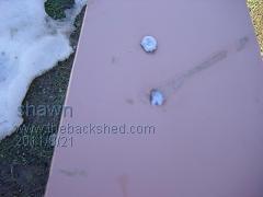
Then a top coat off polyurathane two pack boat paint
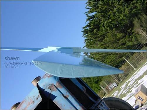
Here is a picture on the front of my trusty old major
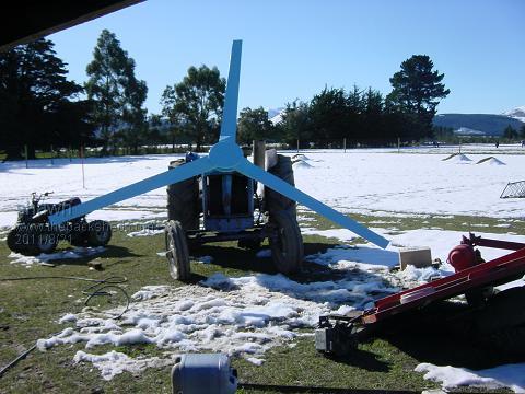
And last my new tower so far
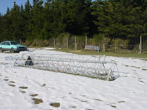
Edited by shawn 2011-08-22 |
| |
Rastus

Guru

Joined: 29/10/2010
Location: AustraliaPosts: 301 |
| Posted: 03:50am 22 Aug 2011 |
 Copy link to clipboard Copy link to clipboard |
 Print this post |
|
Hi Shawn,
Top job on the blades!!Clever lead balancing act.As it happens we have the same tractor although the numbers are starting to dwindle.For their size they are a great work horse.The tower seems fairly light construction but I'm sure you've worked it all out.Cheers Rastus
see Rastus graduate advise generously |
| |
shawn

Senior Member

Joined: 30/03/2010
Location: New ZealandPosts: 210 |
| Posted: 10:59am 07 Mar 2012 |
 Copy link to clipboard Copy link to clipboard |
 Print this post |
|
Bump  |
| |
| |
  Page 2 of 3 Page 2 of 3   |

