
|

|
Forum Index : Windmills : Started on the axial flux
| Author | Message | ||||
| VK4AYQ Guru Joined: 02/12/2009 Location: AustraliaPosts: 2539 |
Hi Gimo That's a real neat job I like the attention to weight reduction. All the best Bob Foolin Around |
||||
| Gizmo Admin Group Joined: 05/06/2004 Location: AustraliaPosts: 5078 |
Started the trial assembly today. My stator will be 360mm diameter, 16mm thick, so I marked out a scrap bit of 16mm MDF. 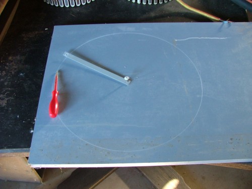
Then I used the 3mm steel stator plates to mark out and drill the stator mounting holes. 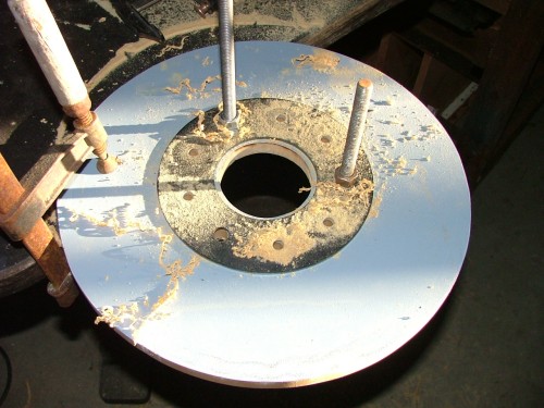
Next I cut lengths of 12mm and 5/16 thread, and used the two stator plates together to position the threads, and welded them to one of the plates. The 12mm threads are for positioning the stator, the 5/16 to help clamp it together and keep the stator flat when its under stress. My welder is a gassless type, so I have a lot of splatter to clean up with a wire wheel. 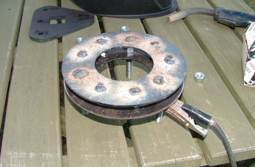
Ready to put together. 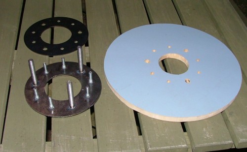
Finished stator. 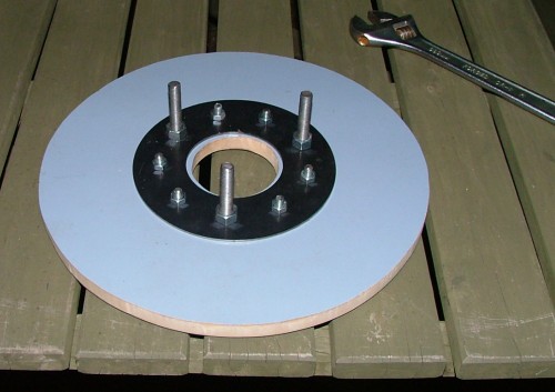
The 12mm threads are longer than they will end up needing to be, I'll cut them down after the whole alternator has been assembled. Next I started on the magnet plates. Here is the front plate with the wheel studs fitted and bolted to the axle hub. 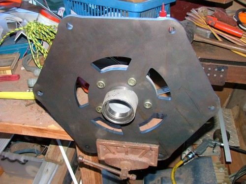
More tomorrow. Glenn The best time to plant a tree was twenty years ago, the second best time is right now. JAQ |
||||
| dwyer Guru Joined: 19/09/2005 Location: AustraliaPosts: 574 |
Hi Glenn Laser cutting these days is great and layer of dark scale flaking best to remove with Lisher belt sander, sand or glass blasting before start welding and painting for best result. dwyer |
||||
Poss Newbie Joined: 27/09/2009 Location: AustraliaPosts: 30 |
Gizmo this is looking great. I'd like to build an axial flux myself so i am watching with eager eyes.I don't post very often but read every post daily. I live in Portland Vic and have plenty of wind.Would be interested in your plans when it's finished.Try using some spatter shield with your welding, makes for easy clean up. Keep up the good work. A brave man may not live for long, but a careful man does not live at all. |
||||
| brucedownunder2 Guru Joined: 14/09/2005 Location: AustraliaPosts: 1548 |
Very nice work Glenn,, Are you going to sell the kit with all the cut parts ? Like watching some of the talent on this forum ,it's a real inspiration .. Bruce Bushboy |
||||
| Gizmo Admin Group Joined: 05/06/2004 Location: AustraliaPosts: 5078 |
Hi Poss, yeah I'll have to get some splatter shield, I've used it before and it works well. Hey Bruce. The plan is to keep this open source. This one is the prototype, and then I'll build a second one based on what I learned. All the plans and cad drawings will be on the web site for anyone to download. I might look into offering the steel parts in kit form for those who would prefer a kit instead of sourcing the parts them selves. It might not even work? You never know what little problem might pop up. One thing I did discover was the back of a axle hub isn't true, only the front, where the wheel bolts to, is flat and true. So I had to rethink that bit, washers where the studs sat home fixed it, but if you have a lathe you could clean it up easily. Glenn The best time to plant a tree was twenty years ago, the second best time is right now. JAQ |
||||
| KarlJ Guru Joined: 19/05/2008 Location: AustraliaPosts: 1178 |
I like how you say the stator is finished 
I'm sure you know you will need to finish another one with coils of wire in it!!! Looking Great.. Karl Luck favours the well prepared |
||||
| Gizmo Admin Group Joined: 05/06/2004 Location: AustraliaPosts: 5078 |
OK, today is another day. Here is the "wooden non functional" stator with the stator bracket and axle fitted. The stator bracket will be welded to the axle, mine is such a tight fit I wont need to weld it until I have the position spot on. Front view.... 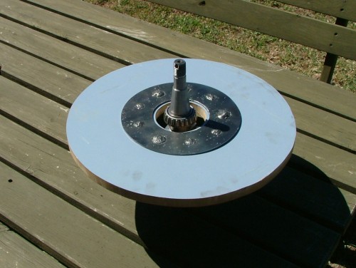
and back view. The 3 nuts are used to adjust the stator foward, backward, and to adjust the angle to get it aligned perfectly inside the magnet plates. 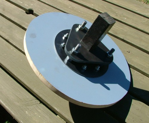
Next photo is the front magnet plate, attached to the hub. 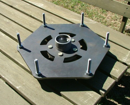
Next we see the stator and axle in place. The axle is now sitting inside the hub. 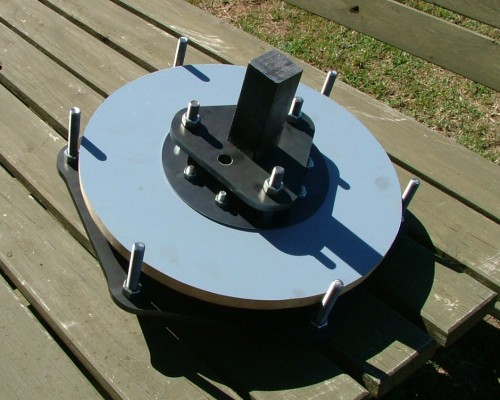
And here we have the rear magnet plate in place. Once the magnets are installed, I would be using 6 long jacking screws to lower the rear magnet plate into position. The jacking screws are then replaced one by one with the threads you see above. 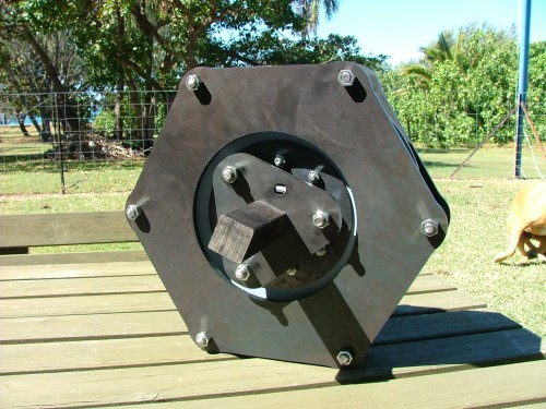
Mounted in a vice to see if it spins OK, rear view. 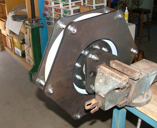
And front view. 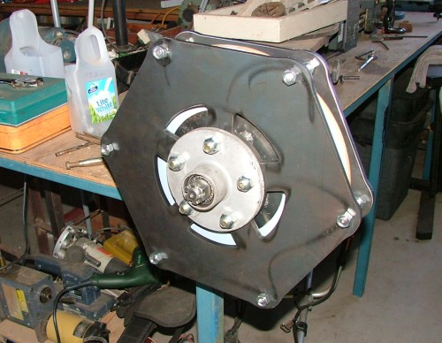
To make it easier to see how it all works together I put a little video on YouTube. http://www.youtube.com/watch?v=z7_fgNNybgc Next step is to start on the stator. Glenn The best time to plant a tree was twenty years ago, the second best time is right now. JAQ |
||||
| shawn Senior Member Joined: 30/03/2010 Location: New ZealandPosts: 210 |
VARY TIDY TOP MARKS!!   |
||||
Bryan1 Guru Joined: 22/02/2006 Location: AustraliaPosts: 1344 |
Hi Glenn, The difference between a drawing and real life are 2 separate things and this new design looks the goods mate. I'm on thinking of using a section of 75x75x6 mm RHS and welding 2 25mm plates on each end then machining each end to hold 2 tapered bearings and by using a lightly held oil seal and a labyrinth seal each end the unit can be filled with oil. The shaft will use 2 lock nuts to adjust the bearings to a zero end float and by using a synthetic oil will ensure cool running. As us Aussies are keen on designing our own style of things when I get my design made I'll also post it as open source. Cheers Bryan |
||||
| VK4AYQ Guru Joined: 02/12/2009 Location: AustraliaPosts: 2539 |
Hi Glenn Top Job mate, Iook forward to the coil development. All the best Bob Foolin Around |
||||
| JA Robby Newbie Joined: 20/07/2010 Location: JamaicaPosts: 13 |
Hi Glenn Looks good bro,looking forward to see the real thing working and pumping some real volts. JA robby No man is an island. |
||||
| ChrisOlson Regular Member Joined: 19/01/2010 Location: United StatesPosts: 60 |
One thing that concerns me a bit about your design is where you're mounting the stator. It has to do with torque - every bit of power your turbine makes is absorbed in torque loads by the stator. The force is generated at approximately the centerline of the coils and transmitted to the stator mounting point, being multiplied by the distance to obtain torque. To get an idea of what I'm talking about, spin up a bicycle wheel or similar. Try to stop that wheel by grabbing it at the hub and you'll find that it's very hard. Grab it on the outside by the tire and it's quite easy to stop it. If you're using a cast stator, made of fiberglass or similar, I don't have much faith in that material to withstand high torque loads being mounted at the center like that. I've broken fiberglass stators on 2 kW machines with only a 3 bolt mount at the outside and had to go to 5 bolt mounting spaced at 72 degrees to prevent them from breaking. If your turbine develops 2 kW of actual output @ 400 rpm the torque absorbed by the stator is around 70 lb-ft, and throwing the shorting switch for emergency shutdown in high winds can pretty easily place up to 3x that amount of torque load on it. -- Chris off-grid in Northern Wisconsin, USA |
||||
| Gizmo Admin Group Joined: 05/06/2004 Location: AustraliaPosts: 5078 |
Hi Chris Yeah I've put a lot of thought into that, I'm well aware there will be a lot of torque to deal with. But I'll be incorporating a few tricks to make the stator much stronger than the conventional axial flux stator. Once I make the mould I'll post some pictures and it will make sense. Glenn The best time to plant a tree was twenty years ago, the second best time is right now. JAQ |
||||
| ChrisOlson Regular Member Joined: 19/01/2010 Location: United StatesPosts: 60 |
Looking forward to the finished product. The workmanship to date looks superb. If you don't mind, and maybe I missed it in the thread here, what are the specs on the machine? Rotor size, projected output power and design operating voltage, basically. -- Chris off-grid in Northern Wisconsin, USA |
||||
| shawn Senior Member Joined: 30/03/2010 Location: New ZealandPosts: 210 |
Hi glen I love this mill. sandwiching blades between two steel plates is good but its only held two the hub buy one 3mm plate will this be enough with 4m blade diameter? |
||||
niall1 Senior Member Joined: 20/11/2008 Location: IrelandPosts: 331 |
Hi Glenn ...erm...now looking back at the cad drawings (shawns point above).. it does kind of seem that the 4m prop would be held on by one mounting plate....if both plates were the same maybe the roots off all three props could be included as part off the inherent strength of the blade hub...kind of ...the studs would go right through the apex off the prop and out the other end ... i really like where this axial build is going....its different ...... niall |
||||
| Gizmo Admin Group Joined: 05/06/2004 Location: AustraliaPosts: 5078 |
Hi guys, There are two mounting plates, the back one is bolted to the trailer hub, the front one, not shown, is bolted to the back one with 15 12mm threads through the blades, 5 per blade. The front plate has a hole in the middle to allow access to the wheel nuts. Glenn The best time to plant a tree was twenty years ago, the second best time is right now. JAQ |
||||
| JimBo911 Senior Member Joined: 26/03/2009 Location: United StatesPosts: 262 |
Keep it up Boss man that thing looks SWEET. The way your going you won't need a hammer at all. Love that Lazer cutting. !NICE!  Jim |
||||
Poss Newbie Joined: 27/09/2009 Location: AustraliaPosts: 30 |
Gizmo how's the progress going? I would be interested in getting the laser cut parts from you. What voltage will you be running, I want to build something suitable for grid tie. A brave man may not live for long, but a careful man does not live at all. |
||||