|

|
Forum Index : Electronics : Variable bench power supply circuit
| Author | Message | ||||
| jgarnold Newbie Joined: 04/10/2010 Location: United StatesPosts: 8 |
>and wondering if this able to take 15 amp instead 5 amps ?? I don't have any experience building high amperage power supplies, but this web site has a number of good ideas... http://www.spaennare.se/psupply.html -Jeff |
||||
| jgarnold Newbie Joined: 04/10/2010 Location: United StatesPosts: 8 |

Here's how to calculate the values for the current limiting resistors... Pins 2 and 3 on the LM723 can be used to limit the output current of the power supply. Inside the LM723, these pins are connected to a transistor. When the voltage applied to the base of the transistor (pin 2) exceeds approximately .6 volts, the transistor will start to conduct. This causes the drive current on the output (pin 10) to be throttled back, which ultimately limits the current from the 2N3055 power transistors. We want a power supply that can be adjusted from 1.25-5.0 amps. R6 is used to select the minimum current (1.25A) and C-LIMIT/R7 are used to control the range up to the maximum current (5.0A). In order for the LM723's internal transistor to turn on, the voltage across pins 2 and 3 must exceed .6 volts. So, the voltage drop across R6 must exceed .6 volts when the output current is greater than 1.25 amps. The value of R6 is selected by the formula R = V/I. So, R = .6 / 1.25, giving a result of .5 ohms. We can now select values for the C-LIMIT pot and R7 resistor which will control the range of current limiting from 1.25A to 5.0A. Once again, this is just another voltage divider. When the C-LIMIT pot is turned completely counter-clockwise, the divider does nothing, so the current limit is 1.25A. When the pot is turned completely clockwise (5.0A current limit), then the voltage divider will divide the voltage across R6 by 4... (1000 + 330) / 330 = 4.03 If more than 5 amps of current is flowing across R6, this will result in a voltage drop of at least 2.5V. The voltage divider will divide this by 4, giving the .6 volts needed to turn on the LM723's current limiting. R6 needs to be at rated for at least 10 watts (20 would probably be better). If the amp was short circuited at the full 5 amps, the power dissipated by R6 would be 12.5 watts. P = (I ^ 2) / R, so (5A ^ 2) / .5 ohms = 12.5W -Jeff |
||||
| dwyer Guru Joined: 19/09/2005 Location: AustraliaPosts: 574 |
Hi Jeff Many thank for your kind information on http://www.spaennare.se/psupply.html and decided to go on number 3 Circuit Layout and will use normal iron core transformer instead using Toroid and at the moment I am running on homemade 24 volt batteries charger by using two four-diode bridge however power supply (need to upgrade) and useing no heasink so l submerge two four-diode bridge in glass of oil as cooling work well for couple of years but useless if l knock it over and spill oil on the floor or workbench 
regard Dwyer |
||||
| jgarnold Newbie Joined: 04/10/2010 Location: United StatesPosts: 8 |
>If the amp was short circuited at the full 5 amps, the power dissipated by R6 >would be 12.5 watts. P = (I ^ 2) / R, so (5A ^ 2) / .5 ohms = 12.5W I probably shouldn't have stated the situation this way. I don't really understand what happens inside a power supply like this when it's dead shorted. If the power supply is current limited to 5 amps, what's the difference between a load drawing 5 amps and a dead short? -Jeff |
||||
Downwind Guru Joined: 09/09/2009 Location: AustraliaPosts: 2333 |
Basically as the amp setting is reached the controller chip limits the power and the amps remain at 5 amp but the output voltage drops. Your calculations for R6 is about right as i changed mine recently to 2 x 1 ohm resistors (10 watt)in parallel to get the minimum amp setting of below 3 amp. The current out for the circuit is only limited by the number of 2N3055 transistors and the wattage rating of R6. You could just use a heavy shunt for R6 to reduce the temperture produced in the resistor (R6) There is very little times i ever require my supply to operate above 5 amp even though it is rated to 10 amp. If the supply was intended to operate at high amperage for a long period of time, i would increase the number of 2N3055 transistors used as the will get rather hot, and ensure you use a large heat sink with good thermo coupling. Pete. Sometimes it just works |
||||
| jgarnold Newbie Joined: 04/10/2010 Location: United StatesPosts: 8 |
In the past couple of weeks since I posted my schematic, I've learned more about how the LM723 operates and also breadboarded one to see how it behaves in "real life". The most important thing that I found out is that there's no way that you can achieve more than a 10:1 ratio between the highest and lowest output voltage. This is because once the internal VREF voltage (7.15 volts) had been divided by more than 10, the result becomes less than .7 volts. This is not enough voltage to forward bias the "error amplifier" transistors inside the LM723. About the highest ratio that I could achieve was 9.7 to 1. So, all of these schematics that you see on the net claiming an output of 2-30V probably aren't going to work... 3-30V or 2-20V are closer to reality. NOTE: LM723 power supplies that can go all the way down to 0 volts require a different design and a negative voltage source. The following LM723 based power supply design is very well thought out... http://www.sentex.net/~mec1995/circ/ps3010/ps3010a.html Even this design can only achieve a 10:1 high/low voltage ratio, but it has a switch to select two different voltage ranges... 0.7 to 6 volts and 3 to 30 volts. I updated my schematic to include more powerful transistors, an overvoltage protection crowbar circuit, and fuses. However, I haven't figured out the values for a couple of the components yet. I also built a case for the power supply. Now, I just need to build the actual supply. 
-Jeff 

|
||||
| Gizmo Admin Group Joined: 05/06/2004 Location: AustraliaPosts: 5078 |
Thanks for posting Jeff. When I put my LM723 based power supply together I did notice I couldn't get the full range. Tanks to your posting I now understand why. My DC supply was about 36 volts, and I wanted to adjust from 1 to 32 volts. I ended up using two pots, one on pin 5 as the fine adjustment, and one on pin 4 as the broard adjustment (or was it the other way around?). It works fine, and I get the full range. Glenn The best time to plant a tree was twenty years ago, the second best time is right now. JAQ |
||||
| jgarnold Newbie Joined: 04/10/2010 Location: United StatesPosts: 8 |
>I ended up using two pots, one on pin 5 as the fine adjustment, and one on pin 4 as >the broard adjustment (or was it the other way around?). It works fine, and I get >the full range. Good idea. Similar to using a switch to select one of two ranges, but your method can select an "infinite" number of ranges. -Jeff |
||||
| jgarnold Newbie Joined: 04/10/2010 Location: United StatesPosts: 8 |
If I had a transformer with two 0-12V secondaries, could I use the following circuit to generate two different voltages? I want a smaller secondary voltage source that can be regulated to +9 or +12 to run some LED panel meters and/or fan. 
I'm calculating the DC peak voltages using (V - (2 * .7)) * 1.4 Subtract off two diode drops for the rectifier and then multiply by 1.4... ((12 - 1.4) * 1.4) = 15 ((24 - 1.4) * 1.4) = 32 Is this correct? -Jeff |
||||
Downwind Guru Joined: 09/09/2009 Location: AustraliaPosts: 2333 |
Why not forget about the centre tap and just use the full 32 volts as its a adjustable power supply and you dial up what you need. I dont follow why you want to use 2 different voltage inputs. Pete. Sometimes it just works |
||||
| jgarnold Newbie Joined: 04/10/2010 Location: United StatesPosts: 8 |
>Why not forget about the centre tap and just use the full 32 volts as its a >adjustable power supply and you dial up what you need. I want to use the smaller secondary voltage *inside* the power supply to power up the LED panel meters, cooling fan, etc. Much more efficient to regulate +9/+12 from +15 than from +32. Looks like my voltage formula is incorrect. It should be ((V * 1.41) - (2 * .7)). Get the peak voltage first and then subtract off the two diode drops. -Jeff |
||||
| TheLaw Newbie Joined: 08/09/2011 Location: United StatesPosts: 1 |
jgarnold, Did you ever figure out the value of the components you were missing? It appears you built the PSU (It looks great!) I'd like to try building yours. Also, are the min and max voltages determined the same on your schematic as they are for the original project? I'd like to drop mine to about 2-20V if possible. Thanks! |
||||
| xsumirx Newbie Joined: 16/02/2012 Location: IndiaPosts: 1 |
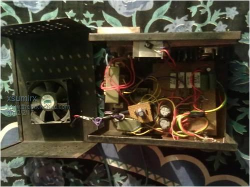
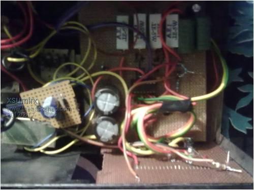
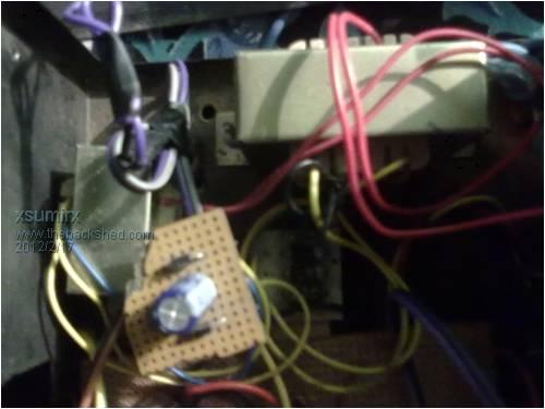
I have made this supply.....and i am very happy with it performance...   
i am posting some pics of my psu 


awesome performance....and nice regulation but will anyone recommends me to a circuit (voltmeter schematics) using ssd. coz i also wanna add ssd display to read the voltage as well as !!!! 
|
||||
| Gizmo Admin Group Joined: 05/06/2004 Location: AustraliaPosts: 5078 |
Not sure what you mean by "ssd". Nice work on the power supply. Glenn The best time to plant a tree was twenty years ago, the second best time is right now. JAQ |
||||
bfgstew Newbie Joined: 27/04/2013 Location: United KingdomPosts: 19 |
Well I have eventually made the unit as per Downinds schematic, I did have to improvise on a few components. The 4 0R1 wirewound resistors are 7W instead of 5W and R10 is a 4k7 pot instead of a 5K one and I could only get hold of a 24V transformer. Anyway, all built up and it didn't blow up when I switched it on (always a good sign) But it does seem weird,, as measuring max output voltage, I get 27.5v AC out of the Tx, then out of the bridge rectifier I get 37.4V DC, but I can only get 19.7V DC max at output, checked Vref on pin 6 and that is at 7.0V, nothing running hot or smoking, so I am at a loss, unless it is purely the Tx being a 24V unit. Any ideas guys? Red to red, black to black and blue to bits! |
||||
bfgstew Newbie Joined: 27/04/2013 Location: United KingdomPosts: 19 |
I did some more testing and found with pot R10 on max I have 14v to ground on my heatsink, on min it drops to 1.7v, all components are isolated from heatsink with correct mounting kits and heatsink compound, if there was any 'leakage' I would have thought it would go up to the incoming voltage of 37.4v or go BANG...........? Red to red, black to black and blue to bits! |
||||
bfgstew Newbie Joined: 27/04/2013 Location: United KingdomPosts: 19 |
Cured the stray voltage, found a single strand of copper wire from a joint to one of the 2N3055 transistors was touching the heatsink, still not cured the low output voltage though...................  Red to red, black to black and blue to bits! |
||||
Downwind Guru Joined: 09/09/2009 Location: AustraliaPosts: 2333 |
Try dropping the value of R9 (390R) to 220R and see if that gives a wider voltage range. I forget now what i done, but i do have a switch on the underside of my original build to allow for higher voltages, by memory i think 0-18v is about all you get from the present circuit, but by changing a resistor value you can increase the output voltage, but it also increases the minimum voltage above zero volts. I have something like 0 - 18v and then 6 - 24v for example. Pete. Sometimes it just works |
||||
bfgstew Newbie Joined: 27/04/2013 Location: United KingdomPosts: 19 |
Thanks Pete, will give it a go later. Red to red, black to black and blue to bits! |
||||
Downwind Guru Joined: 09/09/2009 Location: AustraliaPosts: 2333 |
Incase you dont know you will get around 1.4 times the VAC when full wave rectified to VDC. Then you need to subtract diode loss for the bridge rectifier, which is 2 x 0.6 = 1.2 VDC 27.5 x 1.4 = 38.5 38.5 - 1.2 = 37.3 VDC (close to your 37.4 VDC reading) Also a transformer with no load will always have a higher VAC than its given output rating. The VAC rating will mean it can maintain that voltage at the transformers given current (amps) demand. This has been almost 12 months in the making, it would be good for you to get it finished and working, then you can use it on all those Picaxe projects you have  . (I know you on that forum too, (except i have a different name there) . (I know you on that forum too, (except i have a different name there)
Pete Sometimes it just works |
||||