| |
  Page 2 of 5 Page 2 of 5   |
| Author |
Message |
KarlJ

Guru

Joined: 19/05/2008
Location: AustraliaPosts: 1178 |
| Posted: 02:24am 26 Dec 2009 |
 Copy link to clipboard Copy link to clipboard |
 Print this post |
|
Jimbo, all in good fun not intended as a hit on the head for your efforts, but for a giggle.
Your tower regardless of recent drama at 14m high is quite an achievement
Karl
Luck favours the well prepared |
| |
JimBo911

Senior Member

Joined: 26/03/2009
Location: United StatesPosts: 262 |
| Posted: 05:34pm 26 Dec 2009 |
 Copy link to clipboard Copy link to clipboard |
 Print this post |
|
If I am correct about the 14 meters? It's 47 feet in Yankee Doodle.
Marcus
The concrete base 16" dia and 4'6" deep. The concrete base really just bears the weight (vertical weight) of the mill and mast otherwise the wires do most of the work.
The most difficult thing about the hinge plate is that it pivot's in a FIXED arch and it was difficult to line up all the holes of the plate with the bolts. As the plate pivot's over the bolts (coming down on to the bolts) the farthest bolts from the hinge was not a problem, but the bolts closest to he hinge were a different story. The blots holes will have to be elongated to allow the blots to go through the holes in the plate. I machined the hinge on my lathe, not sure if you have a lathe. The plate is made of 1/2 mild steel. The blots are 3/4". The u blots used to mount the gin pole to the plate are 3/8". I got the idea from Southwest Wind Powers Slipstream 3.7 they have a 45 foot tilt up monopole set up you can buy.
Here is the web address for there hinge plates info in PDF both old and new style plates. Check out pages 13 and 14
http://www.windenergy.com/documents/manuals/3-CMLT-1326_Skys tream_Foundation_Tower_Manual.pdf
The main differences are the old plate is a fixed arch and the new has a variable arch.
The wires are 1/4" dia 1200 lbs working load and 1880 lbs breaking.
Marcus since you will not have side wires to support the mast while lowering you definitely have to have a strong gin pole.
When I first stared using my tilt up system my gin pole bent thankfully the mill was five feet off the ground and just came down on the temporary stand I built. My gin pole is 20'long, 2" sch 40 water pipe reinforced by welding 1/4' thick angle irons along the entire length. If the gin pole bends your mill will follow the direction of the pole. The hinge plate works well but it does need the support of a RIDGE gin pole DO NOT depend on the hinge plate alone to raise and lower your mill.
A lot depends on the weight of your mill and the length of your mast as to how long/ridge the gin pole has to be.
Jim |
| |
gpalterpower

Senior Member

Joined: 19/07/2009
Location: AustraliaPosts: 175 |
| Posted: 01:10am 29 Dec 2009 |
 Copy link to clipboard Copy link to clipboard |
 Print this post |
|
Thanks Jimbo......
WOW....making a mill is not an easy thing to do. all these variables come in to the equation. I ve been thinking heaps about this problem for the last few days. The land area where I am proposing to place this mill is approx 5 m x 6 metres. Not too sure if that is big enought for 4 guy wires or a hinged plate system like jimbos. 4 guys would be easier to manufacture. I have also been thinking along the lines of using 3 lengths of 75mm pipe with fairly large foundatins and meeting all 3 at a point, say 5 metres above the ground. From this point is where it could be hinged using another length of similar pipe, half way along that 6.5m length. The bottom of the pipe could be weighted to allow easy lowering of the mill, while a couple of shorter guys could be placed half way up the mast to half way down the 3 75 mm pipes
if it aint broke dont fix it!! |
| |
gpalterpower

Senior Member

Joined: 19/07/2009
Location: AustraliaPosts: 175 |
| Posted: 01:16am 29 Dec 2009 |
 Copy link to clipboard Copy link to clipboard |
 Print this post |
|
continuation.....for further rigidity.
Marcus.
if it aint broke dont fix it!! |
| |
KarlJ

Guru

Joined: 19/05/2008
Location: AustraliaPosts: 1178 |
| Posted: 12:15pm 29 Dec 2009 |
 Copy link to clipboard Copy link to clipboard |
 Print this post |
|
I abandoned the guy wires in favour of a shorter tower that is hinged Approx 1/2 way up. if you're short on space bore casing is the go, its as heavy as all get out and thankfully readily available in the scrap yards for 1/4 the cost of new.
My tower of 6m is costing about $1000 done and dusted including the concrete. Pole itself is about $800.
Hayden is the contact eastcoastgreenenergy@hotmail.com he uses this 6m monopole tower upto 2KW chinese turbines.
I did have some other ideas for a tilting tower that had no guywires and after the posts from the guy in the USA with robot motors I'm more than confident they are A OK as far as load bearing goes, his much taller than what I had in mind.
Luck favours the well prepared |
| |
gpalterpower

Senior Member

Joined: 19/07/2009
Location: AustraliaPosts: 175 |
| Posted: 11:26am 03 Jan 2010 |
 Copy link to clipboard Copy link to clipboard |
 Print this post |
|
Well after even more thinking on the weekend I thought about option 2 . A second site where I still get good wind even though its 2.5 metres lower than the first planned. It may be better as its 10 metres away from the boundary, something I was always worried about with the first site.( gotta keep the neighbours happy). Would 5 metres either side of the mast, in line and level, be enough for the 2 side anchors if the height to the mill is 8 metres?. Is there a formula or an optium angle for the guys for securing the mast.
Marcus
if it aint broke dont fix it!! |
| |
KarlJ

Guru

Joined: 19/05/2008
Location: AustraliaPosts: 1178 |
| Posted: 03:24am 10 Jan 2010 |
 Copy link to clipboard Copy link to clipboard |
 Print this post |
|
30 degrees is the go.
That said, I reckon steeper angles are OK as long as they dont pull out, ie more concrete and deeper holes, obviously if they are really close to the mast they will need to take significantly more load to do the same job, thus heavier cables may be required
Luck favours the well prepared |
| |
gpalterpower

Senior Member

Joined: 19/07/2009
Location: AustraliaPosts: 175 |
| Posted: 02:52am 06 Feb 2010 |
 Copy link to clipboard Copy link to clipboard |
 Print this post |
|
Thanks Karl,
Will probably plan on 2 sets of guy wires. one below where its hinged and the second just below the blades. What size cable are we looking at and hole sizes for the base and anchors? Any ideas on a hinge. pics or diagrams appreciated.
Marcus.
if it aint broke dont fix it!! |
| |
KarlJ

Guru

Joined: 19/05/2008
Location: AustraliaPosts: 1178 |
| Posted: 03:16am 06 Feb 2010 |
 Copy link to clipboard Copy link to clipboard |
 Print this post |
|
The thing I ended up with is beyond simple....
almost dangerous.
5.5m for the 1st pole 125mm bore casing in 3m3 of concrete, sticks out 4m.
top section is 3.3m long out of 100mm bore casing
pivot is 880mm so call it 3/1 ratio thus impossible to raise and lower easily without lots of precautions
The guy who sold it to me said 1.5m3 of concrete was plenty, get the hole augered to 900mm x 1.5deep rather than back hoe where smallest hole he could dig 1.5m deep was 1800mm long x 1000mm wide, thus more concrete at $170 /m3.
Guy wires the smallest you would want is 6mm in which case you will need almost 80m for two sets of guys, plus turnbuckles, eyes, clamps etc etc etc.
I cant see any change out of the same money as doing the monopole ides.
Hinge in my case is a 3/4" hi-tensile bolt, with two threaded rods for the lower attachpoints.
I reckon this solution could be done for as little as $500 including everything.
Bolts and nylocks were $30, poles could be had from scrap metal yards (even go 6" casing for the bottom to 6m
put 1.5m in the ground gives 4.5m up, then 2nd pole go another 5m 3m up and 2 down, weld on some links for chain to help with raise/lower.
Luck favours the well prepared |
| |
gpalterpower

Senior Member

Joined: 19/07/2009
Location: AustraliaPosts: 175 |
| Posted: 07:52am 06 Feb 2010 |
 Copy link to clipboard Copy link to clipboard |
 Print this post |
|
Karl,
I must admit your monopole does look spiffy (not being rude there!!) Do you have any more up to date pics of your project with the second pole and mill on top. I am still going with the guys as I have allready purchased......er swapped labour( fixed a mates KTM motocross electrics) for 2 lenghts of 6.5 metre x 75mm of gal pipe some months ago, so it looks like Ill continue down that path.
Marcus
if it aint broke dont fix it!! |
| |
KarlJ

Guru

Joined: 19/05/2008
Location: AustraliaPosts: 1178 |
| Posted: 09:14am 06 Feb 2010 |
 Copy link to clipboard Copy link to clipboard |
 Print this post |
|
Marcus all is not lost, the 75mm pipe will be fine for the top 3-3.5m and the other 3m part of the length will work as your lever.
Or use the two lengths you have for the uprights and get another for the top part, that would work fine too, wont get you to 13m but trust me 13m is getting hazardous, need gin pole and anchors for that (the gin pole) too, all getting pretty hairy for the back yard.
ecoinnovation reckons you need 100M of cable to do a 12+m tower.
BIGGER IS BETTER make no mistake but fo the back yard at least if its in two pieces hinged half way, theoretically only half of it comes down, giving you and the neighbours some piece of mind.
Phills is done in 75mm pipe, hinged half way to give almost 8m.... bury 1m in the groung leaves you 5.5m up, attach guy wires there, weld on a bracket/ whatever to hinge the remaining section at 4m below and 2.5m above. this gives you 8m total height, only one set of guy wires and a very safe setup as it will be well balanced.
ie the 4m section below the pivot will offset the weight of the mill head and the top piece of the tower.
Luck favours the well prepared |
| |
KarlJ

Guru

Joined: 19/05/2008
Location: AustraliaPosts: 1178 |
| Posted: 12:55pm 08 Feb 2010 |
 Copy link to clipboard Copy link to clipboard |
 Print this post |
|
how about some mill progress pics Marcus?
Luck favours the well prepared |
| |
gpalterpower

Senior Member

Joined: 19/07/2009
Location: AustraliaPosts: 175 |
| Posted: 06:35am 10 Feb 2010 |
 Copy link to clipboard Copy link to clipboard |
 Print this post |
|
hey karl.
Well i must admit ive been slack with the mill project for a few months now . work has been hectic and regretibly havent done much since before christmas. The mill is just sitting there in the workshop looking at me like Ive neglected her  I had posted some pics earlier on another thread (first mill. a dual) on the 11 dec. but I do have some more to keep you glued to this station I had posted some pics earlier on another thread (first mill. a dual) on the 11 dec. but I do have some more to keep you glued to this station 
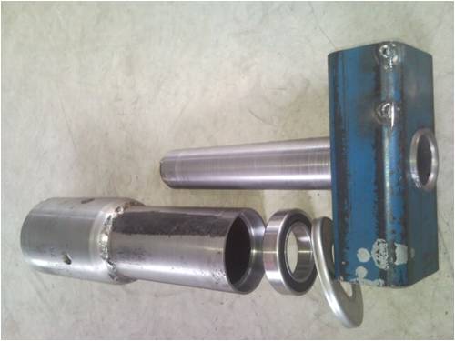
The first one is the pivot base on which the nacel sits. It has 2 x 6008 bearings (like phils) for the cabeling to go thru. I manufactured a stainless steel cover to protect the upper bearing from the weather which has clearance over the upper pipe . 
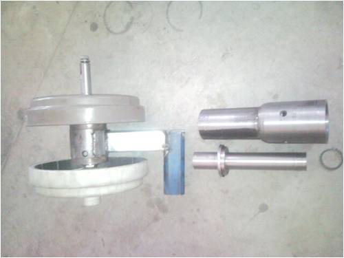
next with the shaft and rotors assembled. this pic includes a circlip which locates under the second bearing holding it all together

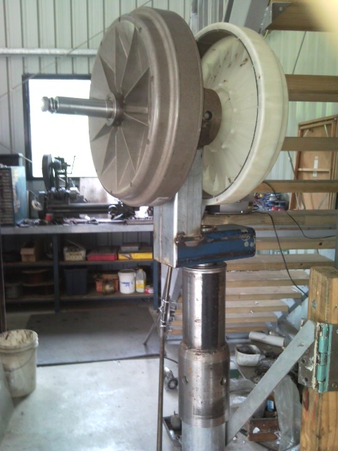
assembled and on my test stand 
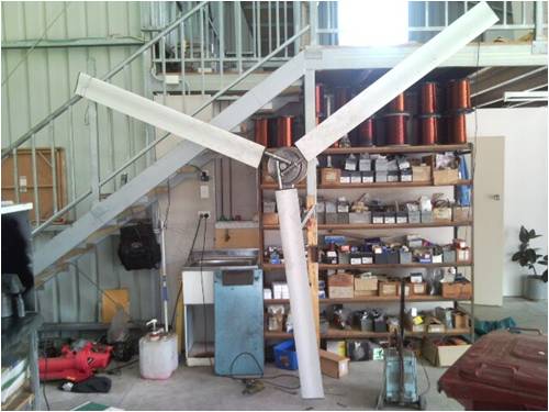
and with blades attached. woooooh!! 3 metre dia fan is quite a big thing when your standing right next to it. even scarier when she is doing a few hundred rpms
hope to get back in to it soon. thanks for your help .....Marcus...
ps. hows your mill going. like to see some more pics too!!
if it aint broke dont fix it!! |
| |
KarlJ

Guru

Joined: 19/05/2008
Location: AustraliaPosts: 1178 |
| Posted: 11:30am 10 Feb 2010 |
 Copy link to clipboard Copy link to clipboard |
 Print this post |
|
I see you have some tilt, to keep the blades away from the tower but.....
Argh.....
what about the offset????
Phill's uses a variable offset and a big 1" bolt to set it.
I'm thinking with no offset you'll need to re-invent the wheel to stop it self destructing.......
I spooled mine up to perhaps 150rpm in the shed with a howling gale coming through, she even self started!
Make sure you get those blade angles identical before you balance, as beleive me it makes a difference.
Mine is so close its not funny any more, I have an open for inspection on my place this saturday.
Hence flat out flogging F&P's on ebay
in fact kicking myself as I sold more than I had!!!!
needed to go and get more. (thats about 25 i've sold now)
Today was painting some new doors (look like glass as I'm da man when it comes to painting new doors with a foam roller) come to think of it next time I paint a mill, i'll be using a brush! coverage is soooooo much better.
Yesterday was hanging a couple of doors and building a new back fence, day before that was buying the doors.
Does the new style rotor on the back mean 60S and 80S?
what system voltage are you going for?
BTW..Dont buy any rectifiers, Pete will be listing some on the site soon that will withstand nuclear war!
think 12 of those puppies I used as a diode block from the battery.....
plus your voltage doublers.....
Luck favours the well prepared |
| |
gpalterpower

Senior Member

Joined: 19/07/2009
Location: AustraliaPosts: 175 |
| Posted: 12:20am 11 Feb 2010 |
 Copy link to clipboard Copy link to clipboard |
 Print this post |
|
Ahhhhh!!! the offset. I was going to offset the tail to one side at the rear of the 3 x 2 rhs(blue section) but do I need to do the front as well?? I can see how Phils is variable with that big inch bolt, but the rear is fixed, apart from the tail to swing .
I think both rotors are the same ...just a different moulding colour.
Probably going for 2 x 80's. voltage is probably going to be 48 as my end goal is to feed back in to the grid, but not sure the best way to go about that. really trying to get away from batteries if possible. Ive heard Bolty uses a modded tc48 and no batteries.
ps... would love to come down for the grand opening inspection on saturday but a 2000k drive south is probably out of the question for the weekend.
Marcus
if it aint broke dont fix it!! |
| |
GOFJ

Newbie

Joined: 22/12/2009
Location: AustraliaPosts: 27 |
| Posted: 05:21am 11 Feb 2010 |
 Copy link to clipboard Copy link to clipboard |
 Print this post |
|
The center of the fan needs to be offset as it is the push on the fan combined with the offset from the mast axis that dictates the torque available to self furl. I am in the process of building something similar but will be mounting the front magnet ring off the fan hub to get the maximum distance between the shaft bearings as well as get the front bearing as close as possible to the fan hub where most of the dynamic loading is occuring.
Jack |
| |
gpalterpower

Senior Member

Joined: 19/07/2009
Location: AustraliaPosts: 175 |
| Posted: 06:19am 11 Feb 2010 |
 Copy link to clipboard Copy link to clipboard |
 Print this post |
|
Thanks Jack for clarifying the concept of how the offset and furling works. Didnt fully understand that side of things but now I do. I ve only tack welded and pressed things together so it wont take much to pull it apart. What is the distance or is there a formula for calculating the offset from the centre of the fan to mast pivot point?
Marcus
if it aint broke dont fix it!! |
| |
GOFJ

Newbie

Joined: 22/12/2009
Location: AustraliaPosts: 27 |
| Posted: 06:47am 11 Feb 2010 |
 Copy link to clipboard Copy link to clipboard |
 Print this post |
|
It is a bit like how long is a piece of string. The heavier the tail and/or the greater the cant on the tail pivot the more offset is needed for a given fan swept area at a given wind speed to get furling at the required fan RPM. You can make an adjustable cant for the tail by having it on a pipe in a pipe with a clamp bolt (so you can twist it to change the angle)or even swop to a new revised assembly or use the gas axe/welder method and then fine tune by adding/removing weight to the tail. For a starting point, if you stand behind the generator (assuming the shaft offset is to the right) the top of the tail pivot shaft leans towards you and is tilted to the left. That is as it starts to furl the tail rises.
Jack |
| |
KarlJ

Guru

Joined: 19/05/2008
Location: AustraliaPosts: 1178 |
| Posted: 08:28am 11 Feb 2010 |
 Copy link to clipboard Copy link to clipboard |
 Print this post |
|
I'd be hitting up Phill for some tips here BUT
in my humble opinionm the go is to weld in the huge bolt and then its adjustable.
If no adjustable is possible then 100mm offset is a good start, Phills the tail is mounted on Aluminium square section and the tail itself is aluminium.
Rationale behind this is longer tail = same mass as shorter tail in steel but more gentle furling and, further back from the prop, so should see some wind,
Quote from Phill "these blades stop lots of wind getting to the tail", hence longer = better.
I;m sure if you ask really nicely Phill will tell you the angle he uses.
Also note you need a tail stop in both directions, one so they dont hit the blades, the other about 15degrees opposite from straight back, ie the opposite direction to furled, this helps it track the wind without bashing it around.
Luck favours the well prepared |
| |
gpalterpower

Senior Member

Joined: 19/07/2009
Location: AustraliaPosts: 175 |
| Posted: 11:00pm 12 Feb 2010 |
 Copy link to clipboard Copy link to clipboard |
 Print this post |
|
I always thought that big bolt was for ease of assembly and disassembly, but theres more to it than that. Ill have to go back to the drawing board for some redesigning.
If Phil is listening I would love to know the off set and tail details ...eg. size and length.
Karl. Been thinking more about the monopole. Looks sporty. I like the idea. less things to trip over in the backyard. If you have ever seen me in a caravan park with lots of tents and guys youll know what I mean.
Marcus
if it aint broke dont fix it!! |
| |
| |
  Page 2 of 5 Page 2 of 5   |

