|

|
Forum Index : Electronics : MOSFET question....
| Author | Message | ||||
| phil99 Guru Joined: 11/02/2018 Location: AustraliaPosts: 2135 |
The 10k between Q1 G and Q2 C doesn't have a number, but it probably isn't needed anyway. |
||||
TassyJim Guru Joined: 07/08/2011 Location: AustraliaPosts: 6098 |
I am not sure what your Vin is but you are putting close to that across gate-source when you press the on button... I hope it's not 12V Jim Edited 2023-01-13 11:48 by TassyJim VK7JH MMedit   MMBasic Help |
||||
TassyJim Guru Joined: 07/08/2011 Location: AustraliaPosts: 6098 |
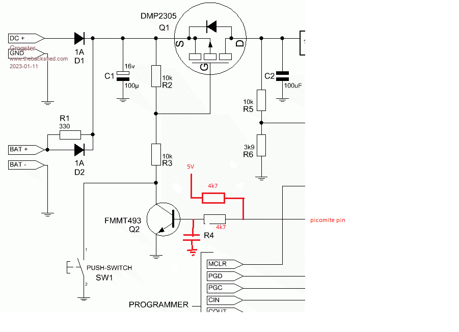
MY solution with more detail  Add resistor to 5V the same value as R4 - 4k7 looks good choice. Add small capacitor across transistor. No other hardware changes needed. On the picomite, the pin powers up as input = high impedance so transistor switches on almost immediately. Voltage on input pin is under 3V so no problems there. To shut down, change pin to output and set low. It will stay low until picomite runs out of puff. Jim VK7JH MMedit   MMBasic Help |
||||
| wiseguy Guru Joined: 21/06/2018 Location: AustraliaPosts: 1156 |
Tassy Jim is right for the first part, the VGS for that FET is the lowest I have encountered on an enhancement FET @ +/-8V. the ones I use are usually a minimumn of +/- 20 to 30V. So add yet another part a 7.5V zener across R2 with the anode connected to D3's anode. For his second solution I dont know enough about the picomite or its operation external to the circuit to offer an opinion. Or you could always leave the circuit as it originally was and tell the user to hold their finger on the button for a few seconds †  Edited 2023-01-13 12:43 by wiseguy If at first you dont succeed, I suggest you avoid sky diving.... Cheers Mike |
||||
| phil99 Guru Joined: 11/02/2018 Location: AustraliaPosts: 2135 |
Red face here too, never considered the possibility of Vgs.MAX being that low. Jim's solution is perfect. |
||||
Grogster Admin Group Joined: 31/12/2012 Location: New ZealandPosts: 9306 |
Excellent posts, thanks very much chums.  Yeah, now that I think about it some more, that was the purpose of R2 and R3 on the original circuit, which Jim has posted above with his additions. The two 10k, act as a voltage-divider to ensure that the gate of the MOSFET never sees more then about -6v with the 12v plug-pack(YES - 12v DC in), or roughly -4.5v when running on the 9v rechargeable battery and you press the button. I have a funny feeling that had that not been pointed out again by Jim, the magic smoke would have got out of the MOSFET on the first attempt! †  Using Jim's arrangement, when first powered on, Q2 will switch on producing roughly 2.5v on the PicoMite pin. †Once you make the pin an output and pull it low, would not the red 4k7 try to pull-up the PM pin to 5v, thus exceeding it's 3v3 maximum? It'd be fine while Q2 is on, but as soon as you switch it off.... Should I add a 3v3 zener across the PM pin and ground do you think? EDIT: Or could I feed Q2 from the 3v3 output on the PM module rather then the 5v, then it should not matter. Edited 2023-01-13 15:44 by Grogster Smoke makes things work. When the smoke gets out, it stops! |
||||
| wiseguy Guru Joined: 21/06/2018 Location: AustraliaPosts: 1156 |
What about just pulling it up to the 3.3v supply instead of 5 V ? I dont see problems I see solutions.....I wish they all worked.......... Edited 2023-01-13 16:00 by wiseguy If at first you dont succeed, I suggest you avoid sky diving.... Cheers Mike |
||||
TassyJim Guru Joined: 07/08/2011 Location: AustraliaPosts: 6098 |
My reasoning is, when the pico pin is driving low, the 4.7k to 5V will be overridden by the 0V output so no worries. I would set the pico pin LOW before making it an output but if you didn't , it should only see the divided 5V or between 2.5 and 3 volts. It will be higher than 1/2 5V due to the 0.6V drop through the transistor base. Using 3.3V instead of 5V would make it 'safer' but I reasoned that the 5V rail will go low before the 3.3 and the pico will stay running until the 3.3 is reduced. Using the 5V gives us a head start on the shutdown process and the pico pin held low for longer. Jim VK7JH MMedit   MMBasic Help |
||||
Grogster Admin Group Joined: 31/12/2012 Location: New ZealandPosts: 9306 |
Excellent, thanks for that clarification Jim.  Smoke makes things work. When the smoke gets out, it stops! |
||||