
|

|
Forum Index : Electronics : Whispergen Stirling gen. coupling to 48vdc with 50 hz H bridge in usa
| Author | Message | ||||
| joeblack5 Newbie Joined: 08/02/2022 Location: United StatesPosts: 19 |
Ah, thank you Murphy, will try. Great to hear poida , then it is now to the transformer section. 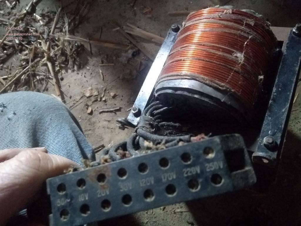 This is from a long time ago.. core 1-1/2"*3".. in my imagination from the days gone it was much bigger.. I have a couple of 2.5kva toroids. All with 4 115 volt windings. Anybody stacked two of these with leaving the windings on and putting the primary through both cores with the secondary (high voltage ) in parallel? Johan |
||||
| joeblack5 Newbie Joined: 08/02/2022 Location: United StatesPosts: 19 |
Do not understand something about transformers. With your example poida..2 kw toroid core starting a compressor and measuring a 12kw load. Is that driving the core far in saturation? Is the current measurement in that case still relevant to the startup of the motor or is a large part of the peak due to saturation of the transformer core. Similar for the motor itself.. how much if the startup surge is related to overcoming the rotor inertia and how much is the mote core itself driven in saturation? Johan |
||||
| Warpspeed Guru Joined: 09/08/2007 Location: AustraliaPosts: 4406 |
Johan, core saturation never occurs from over current in a transformer, only from over voltage. The flux in the core depends on the number of turns, the core cross section and the applied voltage (and frequency). Current never comes into it. So you wind your transformer and it transforms the voltage on the primary to the voltage across the secondary. How much current it will safely handle depends only on safe temperature rise in the wire. That sets the transformer continuous power rating. Provided the whole thing starts off running fairly cool, it can handle massive surge current for a short time. Thermal mass slows down the temperature rise, so short term surge loads are not a problem. From no load to full load, the flux in the transformer hardly changes at all. Its only the current in the wire that changes. Cheers, Tony. |
||||
| joeblack5 Newbie Joined: 08/02/2022 Location: United StatesPosts: 19 |
Thank you warpspeed. Ouch, I just was reading up on that and have to do more since I do not understand. I guess it is hard to grasp as I was thinking that the. Magnetic field is created with a current. So I assumed that increasing the current thru the wire would eventually saturate thea core.. Or different said the flux increase is not linear with the current increase. I am confused, it is late in the night over here. Coffee is a bad thing. Johan |
||||
| Warpspeed Guru Joined: 09/08/2007 Location: AustraliaPosts: 4406 |
The magnetic field is produced by current in a choke or electromagnet which is most often dc anyway. A totally different design technique is required for that. Transformers are very different. Faraday's law ties up all the variables for flux in a transformer, and current is not a part of Faraday's formula. Here is a handy on line transformer flux calculator: https://www.daycounter.com/Calculators/Max-Flux-Density-Calculator.phtml Number of turns Frequency .00006Mhz (four zeroes for 60Hz) Core cross sectional area in square Cm. Then hit calculate. A transformer never normally sees any dc, although it might if its an audio transformer in an old tube amplifier or something really odd like that. So just ignore the optional dc entry. What happens is the voltage across the primary creates a very slight current flow, which induces a back EMF across all the windings including the primary. When that back EMF equals the applied primary voltage there is no further current increase. It settles down to some small no load idling value. Think of it as Xl inductive reactance. That will be high enough to limit current to the zero load idling current. Xl might be say 1K ohms and with 120 volts applied idling current might be 120mA for example. The flux in the core will be sufficient to create that 120v back EMF in the primary to exactly balance the applied 120 volts. If you then load the transformer up to ten amps 1.2Kw in the primary, the primary current will actually be 10A + 120mA and the flux in the core remains the same. Its all rather weird, and difficult to get your head around. To me, the most amazing thing about all this, Micheal Faraday figured it all out 200 years ago back in the age of horses, sailing ships, muzzle loading guns, and swords. Micheal Faraday was a very smart cookie indeed. Edited 2022-02-10 18:54 by Warpspeed Cheers, Tony. |
||||
| joeblack5 Newbie Joined: 08/02/2022 Location: United StatesPosts: 19 |
Thank you warpspeed for taking me by the hand and I appreciated the Maxwell and Faradays formulas when I was studying electronics. I went late to bed , after midnight ,could not sleep anymore and up early now. Haha. But where does the power come in? the faraday formula has no current. An unloaded open secondary reduces the transformer to an inductor? And then the saturation is clearly there. What is the scenario then with an almost shorted secundary? Can one simplify with zero ohm windings? Johan |
||||
| Warpspeed Guru Joined: 09/08/2007 Location: AustraliaPosts: 4406 |
Yup, it becomes a simple inductor with only the primary connected. Its just an inductor with some finite series resistance. Current is determined almost totally by inductive reactance Xl When you look at this, its just a long length of wire coiled up, but it has a much higher AC impedance than just the ohmic resistance of the wire by itself. The reason is the mutual coupling between the turns creates a back EMF that opposes the applied EMF. It takes a (usually small) amount of current to do that, but the more efficient the coupling between the turns and the more turns the higher the inductance and the more efficient and inductive it all becomes. Now with a given coil of fixed turns and fixed dimensions, it requires a certain amount of magnetic flux swing to induce the required EMF in the winding. The core could be air, or steel, or ferrite, it does not matter. Its the flux swing cutting through the turns that determines the induced EMF in those turns. Faraday's formula determines that required flux swing in terms of number of turns, core cross section, voltage and frequency. Core material does not even come into it. Now our (usually small) current is what generates the flux in the core, but how effective that is depends on the permeability of the core material. An air core will require a LOT more idling current than steel to reach our required flux swing. We say the steel has a much higher permeability than air, maybe 2,000 times higher. So adding a steel core increases the inductance and reduces the idling current, but the flux swing required is independent of the core material. So we have our primary idling away with 120 volts and 60Hz applied to it and our primary current is very small because our steel core has increased the inductance sufficiently. If we replaced the steel with something else, or idling current would probably be greatly increased, but the flux in the core would not have changed. Now if we apply some load to a secondary it gets interesting.... Current in the secondary loads down the magnetic path and tries to REDUCE the flux in the core. This has the effect of reducing the Back EMF in the primary that is opposing the applied EMF. The result is primary current increases because of the apparent drop in inductance by an amount required to get the required flux swing back up to what it was with the transformer unloaded. The secondary load current reflects back into the primary dependent on the turns ratio. You can keep adding secondary load, and the primary current keeps increasing in proportion, the primary draws however much current it takes to restore the flux swing back to its original unloaded value. A dead short across the secondary effectively becomes a dead short across the primary. Current will not be infinite because of the ohmic resistance of both primary and secondary, and there will still be some small leakage inductance created by flux that sneaks around bypassing the secondary winding. The other aspect of this is the flux required to generate the opposing back EMF in the primary. If we increase the primary voltage, the flux swing in the core must also increase. That is where core saturation comes into the picture. We need enough turns, or enough core cross section to keep flux swing below magnetic saturation. Lower frequencies or fewer turns also lead to core saturation. A better core material lowers idling current but has no effect on the required flux density required by the winding. I hope this helps, its all a bit abstract and not very intuitive. Cheers, Tony. |
||||
| poida Guru Joined: 02/02/2017 Location: AustraliaPosts: 1418 |
Warp will explain really well anything you want to know about transformers. here is the post I did measuring peak current during the compressor start. https://www.thebackshed.com/forum/ViewTopic.php?TID=9409&P=47#166980 and the following post looks at DC current values. wronger than a phone book full of wrong phone numbers |
||||
| Warpspeed Guru Joined: 09/08/2007 Location: AustraliaPosts: 4406 |
Motors and transformers can only be magnetically saturated through overvoltage, which can never really occur in normal use. What can kill either is sustained overload which simply burns out the windings from over current. That is a thermal limit, and time of overload is a very big factor. But massive short term overloads are quite sustainable given sufficient time to cool down before you do it again ! Motors, particularly those that start up under full load are sometimes rated for "starts per hour" on the rating plate. That can be a major issue with machinery that cycles on and off. A few years back I did an energy audit of my home appliances, and noted my refrigerator was rated as 127 watts running, 350 watts defrost mode on the rating plate. And indeed that was the case. I connected up a current transformer to a digital oscilloscope, and was rather surprised to measure half cycle current peaks of up to 19 amps, which gradually fell away over about a second to the rated normal running current of half an amp or so. An inverter transformer should handle that just as well as the windings in the motor. How the mosfets in the inverter may respond to that kind of surge, is a very different matter. Cheers, Tony. |
||||
| joeblack5 Newbie Joined: 08/02/2022 Location: United StatesPosts: 19 |
Thank you, I can follow that but sething is missing...if it is not saturation then what and why would I not use a tiny tiny 1" by 1" transformer core with a wide space for all the windings and load that with 5 kva?? Here some pics from inductees I had laying around. To far out in the boonies.. no upload. Johan |
||||
| Warpspeed Guru Joined: 09/08/2007 Location: AustraliaPosts: 4406 |
You could certainly design a transformer like that, ultra skinny core, and a huge massive great hole for the winding. But... that skinny core needs a LOT more turns on it to keep the flux level low enough with only one square inch of cross section. Its flux DENSITY that leads to saturation, and a skinny core only allows a small amount of flux to flow in such a restricted core cross sectional area. Turns per volt requirement will end up being very high. All those extra needed turns are going to fill up your big hole rather quickly, and there will still be a need for wire heavy enough to carry the current to support 5Kva. All those extra turns will add considerable series resistance which is not a good thing for either voltage regulation, or for temperature rise. All those extra turns of heavy copper wire will cost you a lot more dollars than adding more steel to the core and using less turns. So what you end up with is a very low cost steel core, and a very expensive large copper winding that has a very high copper loss, and very poor voltage regulation. If you go the opposite way, an enormous core with only one turn, you can run a massively high total flux level, maybe even 120 volts per turn  Flux density will be low because the core cross section is so very high. It will have superb voltage regulation, and minimal copper loss and minimal heating at full load. The big down side is core loss (measured in watts per pound) due to hysteresis and eddy current loss in the steel will be excessive. A core with ten times the mass may have an idling current ten times as high at a given flux density. The large core is probably going to hum and get hot and draw a lot of idling power even with zero load. Probably not ideal either. So we end up with the core manufacturers producing core dimensions over a useful range of proportions that offer a good compromise. And you always have the option to stack cores or go thin if that offers you some particular advantage for an unusual application. Then its an iterative process, the first core might be too big, the winding fits easily with a lot of extra space left. So your next guess is to try a smaller less costly core. That might be too tight to fit sufficiently heavy wire or enough turns. So rinse and repeat. You may find idling power or copper losses higher than you would like, so you make another attempt. There is no one shot formula to design a transformer from first principles all in one go. Decide what is most important for your application, and optimize that, and compromise on some other less critical factors. That is how its done. Edited 2022-02-12 13:36 by Warpspeed Cheers, Tony. |
||||
| poida Guru Joined: 02/02/2017 Location: AustraliaPosts: 1418 |
Warp said "..Decide what is most important for your application, and optimize that, and compromise on some other less critical factors. That is how its done.: I agree with this. My transformer optimised for quick and dirty and low effort. So I took a 3kW toroid with two windings of 240V. I leave both in place and put a primary winding in it using too small copper area cable but the correct voltage or turns. This is my home inverter's transformer. It gets a bit too warm, due to the too small primary winding copper area that is DC resistive loss. But it does the job. Not anywhere as good a job as all of us here. But I like quick and dirty (hopefully not making fires along the way) My advice to you is get it going with something. Learn what drawbacks there are. Make a better one, with less drawbacks. See how it goes Then you are now in a position to maybe specify something close to what you need if you are going to have a commercial supplier make it for you. wronger than a phone book full of wrong phone numbers |
||||
| joeblack5 Newbie Joined: 08/02/2022 Location: United StatesPosts: 19 |
I think I am catching on, interesting feeling that you think you think you know something and find out that you never figured it out. I have wound many transformer over the years ..upto rewinding the flyback transformers from tube color television sets. Never bothered with the if and why. Built some small inveterters for a cdi ignition in my Citroen 2cv4. Just followed the transformer formula core square area versus power and frequency. Thank you all for the teachings. Johan |
||||
| Warpspeed Guru Joined: 09/08/2007 Location: AustraliaPosts: 4406 |
Serious commercial transformer design is one thing, but for us amateur home brew inverter guys, its usually a case of repurposing material we already have, which in many ways can greatly simplify things. Usually we start out with just the core, preferably a toroid, but E and I laminations will work. Measure the cross sectional area of both the steel and the hole. Now we know that voltage is proportional to turns, and at a given current density in the wire, wire area will be proportional to current. As volts x amps will work out to be equal in both primary and secondary, we can see that there will be an equal required copper cross sectional area in primary and secondary, and so we allot half the hole cross section to each winding. In the case of a rectangular E/I core its just half the hole height to primary, half to the secondary. For a toroid its also splitting the hole area in half. The first winding to go onto the core should reduce the remaining hole diameter by 30% the second winding should fill the remaining 70% of the original hole diameter. Its actually root two or 0.7071 or 70.71% to get exact theoretical areas. Now using the core magnetic cross sectional area, the voltage, and frequency, and assuming a suitable flux density of 10,000 Gauss (or 1 Tesla in metric) we can use an on line calculator using Faraday's formula to calculate the required turns. One Tesla is very low in the great scheme of things, but it will greatly reduce core loss and idling power. For inverter application idling power is critical to minimising required overnight battery capacity. Anyhow, we now know the turns requirement and the available space for those turns. So we try to figure out a suitable wire size that will use up as much of the available space as possible. The thickest wire that will actually fit, the higher or final safe power rating will be. A conservative estimate of four amps per square mm of copper will be about right for sustained continuous power. Of course once its built you can run it as hot as you dare, but figure on 4 amps per sq mm as easily achievable at the early design stage. Stacking two cores doubles the core cross section, and halves our turns requirement. So we get to use much thicker wire which should allow a theoretical doubling of the current rating and hence twice the final power rating. Those are the bare bones basics, and a quick run through of the numbers will give you a pretty good idea of the potential grunt a prospective core may be capable of. Running at a low 1 Tesla flux density, expect a transformer idling power of around 20 to 30 watts for a 5Kva toroid would be pretty typical, and more like about 80 watts for E and I laminations of much lesser grade of steel. A second advantage of running at a very low flux density is a much reduced power surge at initial power up. Commercial toroids are often wound to operate at up to 1.7 Tesla, and they can really jump from a massive breaker popping and fuse blowing surge at power up. That huge surge can be very mosfet unfriendly.... So if planning to use an existing mains winding that is already on a core, it may be fine, but test it for any excessive turn on surge. Also measure the idling power, it might be rather high for an inverter. That can all be fixed by adding extra turns, but that may shrink your hole down leaving insufficient space for a nice fat primary. But you may be lucky, and if so, it will save a huge amount of work. Cheers, Tony. |
||||
| joeblack5 Newbie Joined: 08/02/2022 Location: United StatesPosts: 19 |
Actually this all good news.. in my case the Stirling cannot deliver more then a 1000 watt..so a 1000 or 1500 watt core should be large enough. Standby losses are not important because the system will be shutdown when not in use. Now for the startup the peak power might be 7 times as much but then it is only there for 2 sec and all is good for the next 24 hours. Some smaller cores laying around. 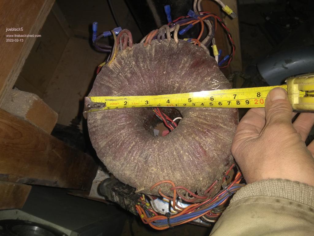 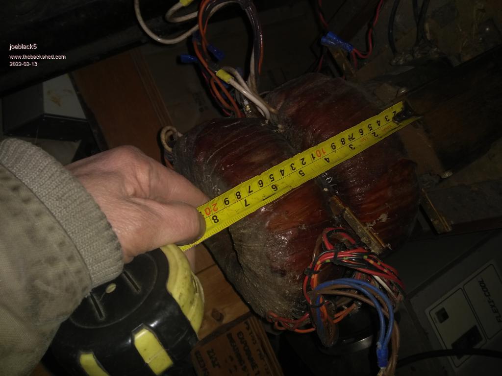 Some inductees laying around 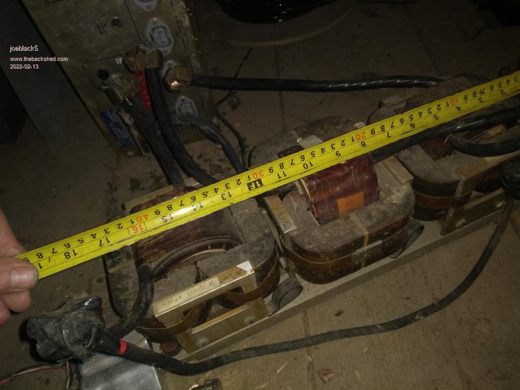 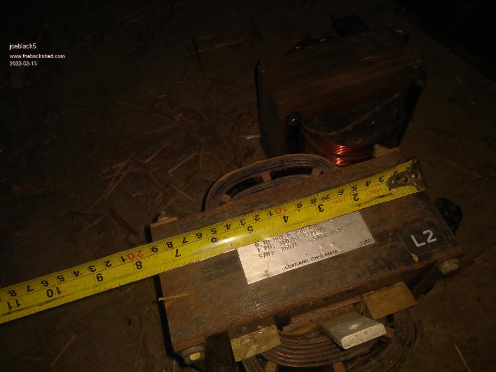 |
||||
| Warpspeed Guru Joined: 09/08/2007 Location: AustraliaPosts: 4406 |
Time to do some testing and measurement. Its common practice to wind the highest voltage winding onto the core first. That will be the thinner wire, which leaves a less lumpy surface over which to wind the heavier secondary wire. As most transformers these days are voltage step down, usually the secondary is placed on top, which can be easily removed, leaving the original mains primary on the core. Suitability of the original primary depends on your tolerance for idling current and initial inrush current. Both of those can be fairly easily tested. Cheers, Tony. |
||||
| joeblack5 Newbie Joined: 08/02/2022 Location: United StatesPosts: 19 |
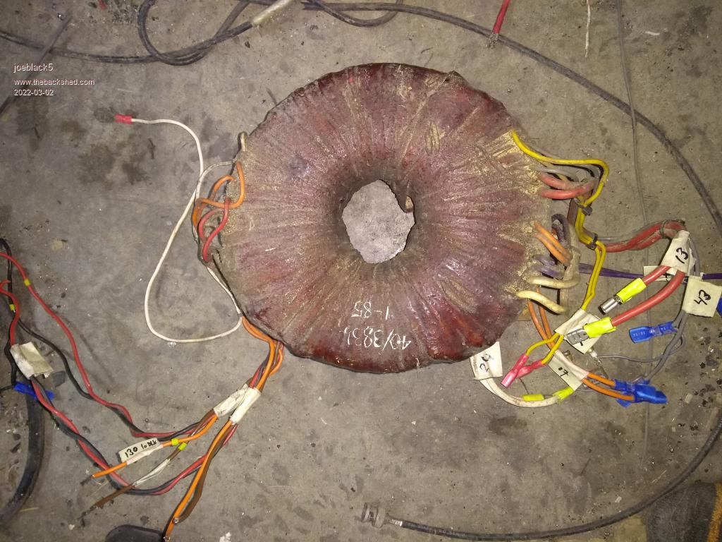 I found two toroid transformers from old surplus military equipment. Outer diameter 7.5" and height is 3-1/4" ... including windings and insulation. I ohmed some winding and found what I assume is the original primary. 0 to 110-120-130 Applied with a Variac voltage to the 0-120 winding and measured the current. 70 VAC...35 mAmp This is measured at 60 HZ.. My application is 50 Hz 80 40 90 44 100 51 110 59 120 70 130 89 140 116 At 110 Volt the curve gets steeper and at 130 Volt it goes up fast. There are two identical primary winding sets so I can use this for 240 Volt. When 120 VAc is applied at the 120 Volt primary the I get 24VAC and 13 VAC at the secundary. The secundary windings look like 10AWG. transformer weight 20.5 LBS. Another toroid transformer i have has the same dimension , same weight and states 2500VA. I guess the 24 and 13 v secundaries in series are a bit much for an 48V sine inverter. It gets a bit better when I would use the 130V primaries. No by chance I have two the same surplus transformers. How bad would it be to parallel two transformers together? Not sure i need that for only 1KVA load from the stirling generator. Johan Edited 2022-03-02 09:33 by joeblack5 |
||||
| joeblack5 Newbie Joined: 08/02/2022 Location: United StatesPosts: 19 |
As a newby I am not so aware with the internal struggles in the forum..so I am a little bit behind but with warpspeed absent and coming back or not I want to thank him for his help with educating me. Hope you come back Tony. Johan |
||||