
|

|
Forum Index : Electronics : Circuit to flash one LED then the other at about a second each.
| Author | Message | ||||
| Solar Mike Guru Joined: 08/02/2015 Location: New ZealandPosts: 1138 |
That's a very clever design there wiseguy, looks like it will work, I would never have thought of that; but something more complex comes to mind. Export from DipTrace and screen capture to png file. Cheers Mike |
||||
| wiseguy Guru Joined: 21/06/2018 Location: AustraliaPosts: 1156 |
Ok here goes for a schematic without having to go pdf. 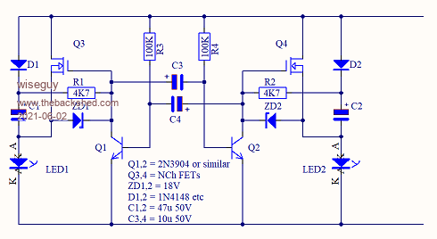 Sorry for this essentially useless post.....I created it with "getgreenshot" straight from Altium into a png. If at first you dont succeed, I suggest you avoid sky diving.... Cheers Mike |
||||
| wiseguy Guru Joined: 21/06/2018 Location: AustraliaPosts: 1156 |
Thanks for the compliment. "But something more complex comes to mind" had to laugh at that. In its first iteration it had 4 Fets 2 transistors and a lot more stuff. Half the fun was trying to minimise the component count and in the process make most remaining components perform more than 1 task ! If at first you dont succeed, I suggest you avoid sky diving.... Cheers Mike |
||||
| Warpspeed Guru Joined: 09/08/2007 Location: AustraliaPosts: 4406 |
The most minimalist design I can think of uses a CMOS chip as the oscillator and a couple of small P channel mosfets. 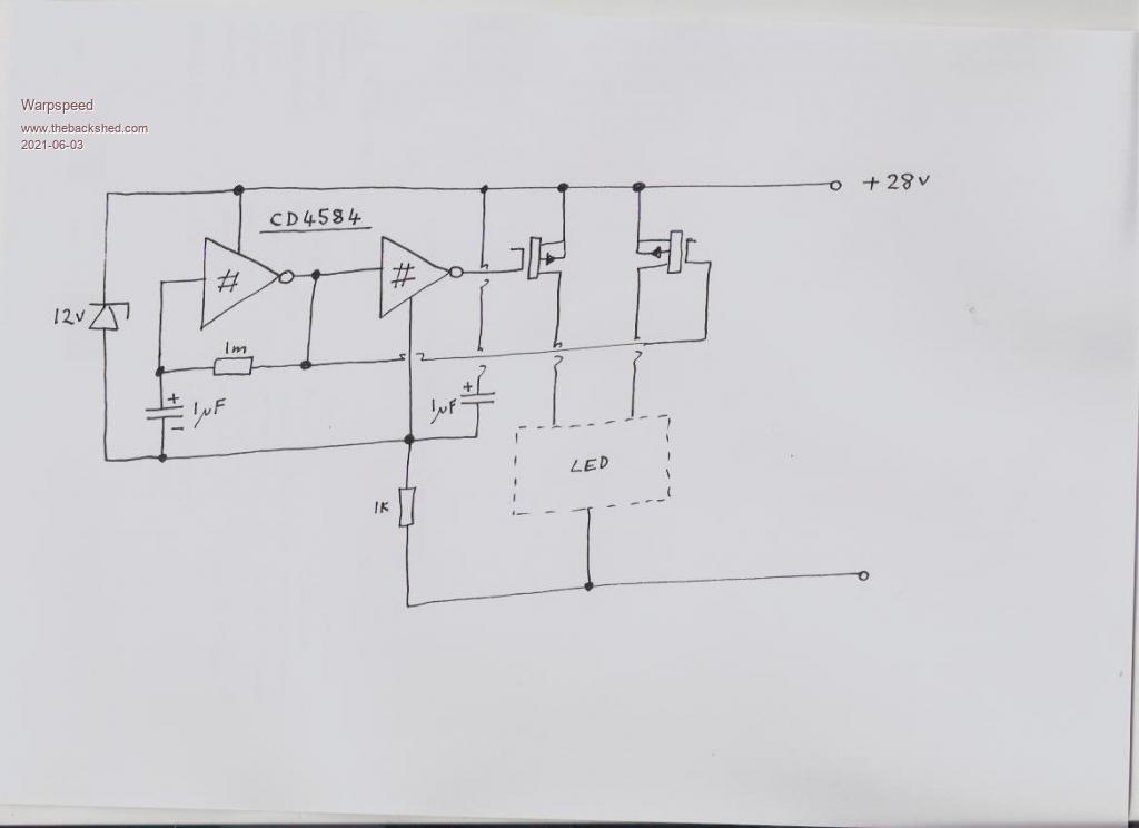 Cheers, Tony. |
||||
| bob.steel Senior Member Joined: 27/02/2020 Location: AustraliaPosts: 188 |
Hey Thanks . I wasnt complaining . Don't get me wrong . I'm just not much of a circuit maker . I usually connect something wrong . I'm building your circuit now . Making the board though is another matter. Edited 2021-06-03 05:35 by bob.steel |
||||
| bob.steel Senior Member Joined: 27/02/2020 Location: AustraliaPosts: 188 |
Warpspeed I'm trying to understand how Mosfets work on the negative . If I took your circuit and put the Lights on the positive side of the MOSFETS could N channel mosfets be used then? Could I invert the cmos outputs to achieve the same thing? Edited 2021-06-03 11:44 by bob.steel |
||||
| phil99 Guru Joined: 11/02/2018 Location: AustraliaPosts: 2135 |
No, for Warpspeed's design if the LED lamps are tied together at the negative end the MOSFETs have to be P-channel. If you want to use N-channel MOSFETs Wiseguy's circuit is the best option. Capacitors C1 & C2 provide the required voltage boost to drive the gates. The zenner diodes, when forward biased turn the MOSFETs off and when reverse biased limit the gate voltage. Very clever. |
||||
| bob.steel Senior Member Joined: 27/02/2020 Location: AustraliaPosts: 188 |
I have spent the last 3 days working on understanding and using Kicad. Got a few problems to sort out but I'm getting there for a board . Ill throw my schematic up here for comment if I may. Also I built the circuit today , roughly on vero board but its a start . Used electrolytic capacitors as that's all I had , no tantalums ,and I used 2655 transistors and BUK456 Mosfets . It does not work at this stage but it draws no power when connected. On connection it flashes each led briefly and then stops. I put a couple of LED's in with 330 ohm resistors to facilitate a test. So I'll have a break and go do something else for a while then come back and check the circuit again. Probably something I've done . My Kicad project.zip Edited 2021-06-06 16:55 by bob.steel |
||||
| wiseguy Guru Joined: 21/06/2018 Location: AustraliaPosts: 1156 |
If R3 & R4 in my schematic were left unconnected instead of being joined to the + supply it would behave as you have just described. Sorry I dont have Kicad so could not check your schematic. PS: Clarification required, both LEDs flash at the same instant or alternately ie one flashes & then the other ? - I am assuming the latter, alternately re my R3,4 comment above. Edited 2021-06-07 00:58 by wiseguy If at first you dont succeed, I suggest you avoid sky diving.... Cheers Mike |
||||
| bob.steel Senior Member Joined: 27/02/2020 Location: AustraliaPosts: 188 |
They appear to flash at the same instant. then stop. R3 and R4 are connected in. 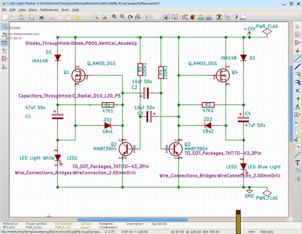 Edited 2021-06-07 06:38 by bob.steel |
||||
| wiseguy Guru Joined: 21/06/2018 Location: AustraliaPosts: 1156 |
R1 & R2 should be 4K7 not 47K. In your schematic it appears as though R1 is shorted out - the line through the centre needs to be deleted, otherwise a good effort. If at first you dont succeed, I suggest you avoid sky diving.... Cheers Mike |
||||
| phil99 Guru Joined: 11/02/2018 Location: AustraliaPosts: 2135 |
The brief flash at power up would be due to initial charging of C1 & C4 through D1 & D2. If it still fails to oscillate after changing R1 & R2 and removing the bridge across R1 it could be caused by the number of LEDs in series in the lamps. In that event adapt Warpspeed's CD4584 oscillator circuit to drive Q2 & Q3 via 10k base resistors. The 1k series resistor in the negative supply must be moved to the positive supply and the negative of the oscillator tied to ground. Remove C2, C3, R3 & R4. |
||||
Grogster Admin Group Joined: 31/12/2012 Location: New ZealandPosts: 9307 |
Agreed!  Very clever.  Smoke makes things work. When the smoke gets out, it stops! |
||||
| phil99 Guru Joined: 11/02/2018 Location: AustraliaPosts: 2135 |
Had another thought (it's a long time between them - getting old), if the lack of oscillation is due to the nature of the LED lamps it may be possible to overcome it by putting a resistor in parallel with each lamp. Try 2.2k 0.5W or 1k 1W. |
||||
| wiseguy Guru Joined: 21/06/2018 Location: AustraliaPosts: 1156 |
"Had another thought (it's a long time between them - getting old)" - there are a few here that I'm sure can relate to that..... I was beginning to doubt my "clever" circuit so with thoughts of having to confess here that it was actually a dead duck I breadboarded it up. I am happy to report it does work like a charm. With regard to the LEDs impedance being an issue it works fine from an open circuit LED (need to use a CRO to prove it....) to high current load >1A. I used BUK455 60s for the FETs, 2N3904 for the transistors, 18K instead of 4k7 (18Ks were already on the bench lying around), 22u 50V in lieu of 10u 50V and 180Ks instead of 100Ks. Flash Rate was ~ 1 second on 1 second off which was about right. I suggest using 4K7s instead of the 18Ks though - the FETs were a bit slower to turn on so they might warm up a bit with heavier loads. With regard to flash rate if you already have the 10u 50V caps just use 390/470Ks instead of 100K and you should get a similar 1S flash rate. Don't give up on it Bob (and dont forget to connect the Drains to +24 - the LEDs give a brief flash on power up then nothing)...... I thought it was a dead duck for a minute! Check orientation of zeners and semiconductor pinouts etc - it will work ! The good news is that the circuit and PCB you've been playing with is ok, no changes required. Edited 2021-06-09 11:55 by wiseguy If at first you dont succeed, I suggest you avoid sky diving.... Cheers Mike |
||||
| bob.steel Senior Member Joined: 27/02/2020 Location: AustraliaPosts: 188 |
Thanks Mike. Have not got it to go yet and was gonna go to P channel mosfets and ordered some . Got about 100 N channels around that I just accumulated from auction . I worked on it and now both led's come on and stay on. (temp leds with 1K resistor on each line. Nice of you to test it out though . Now I will try rebuilding it and see if that fixes it. I have avoided using the real lights so far as I must dismantle it to get daytime operation but will try that too, Edited 2021-06-09 19:53 by bob.steel |
||||
| wiseguy Guru Joined: 21/06/2018 Location: AustraliaPosts: 1156 |
If both LEDs are on then both FETs are on. That means that Q2 & Q3 are both off - which is not really possible if they are connected correctly, they should toggle on and off alternately. The 2655 transistors are a bit different to usual T092 pin out. With the flat face towards you and pins facing down from left to right is emitter, collector & base. You should get yourself a plug in board for circuit testing like this It is simple to use and fast - this circuit can be built and tested in ~ 15 minutes. If you use telephone wire (single strand ~ 0.7mm) about same diameter as a resistor lead it is easy to strip and connect points together. If at first you dont succeed, I suggest you avoid sky diving.... Cheers Mike |
||||
| bob.steel Senior Member Joined: 27/02/2020 Location: AustraliaPosts: 188 |
I have a hard connected board that has both leds on . So I have to play with the transistors and see whats what. Good ideas you have sir. My old man was a PMG linesman /Technician/Instrument Maker while alive and I have rolls and rolls of telephone twisted pair but had never thought to use them on the breadboards I have. Those damn Dupont connectors annoy me as every time I go to use them the bloody plastic bits fall off. Thought I'd show you some of my working environment . You will get a laugh from that ! I breadboarded the circuit again using the same components and this time I have nothing happening at all . No current taken at all. So between the two I should be able to find the problems. I'm building a bathroom atm so won't get to it but spasmodically. Thanks.  |
||||
| wiseguy Guru Joined: 21/06/2018 Location: AustraliaPosts: 1156 |
What I'd like to know is how you keep your desk so neat ! A bit of Trivia. Jim Williams who was arguably one of the worlds best analog engineers had a similar looking desk, after his passing, his bench untouched entered their company's history museum. Jim's desk: 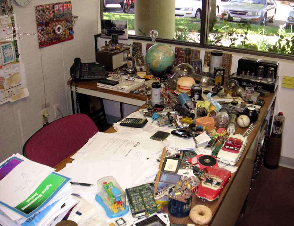 Jims Bench: 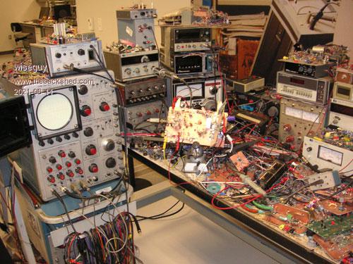 Jims Lab:  Jims Museum bench: 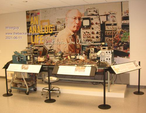 Occasionally I peruse my bench & have comfort knowing I'm following great footsteps & in the company of greatness...... OTOH my wife says when I pass she will hire a big skip (for me & the bench). If at first you dont succeed, I suggest you avoid sky diving.... Cheers Mike |
||||
Grogster Admin Group Joined: 31/12/2012 Location: New ZealandPosts: 9307 |
Jim's lab - wow.......  My lab is also pretty messy, but my hat tips to Jim's lab photo I think. 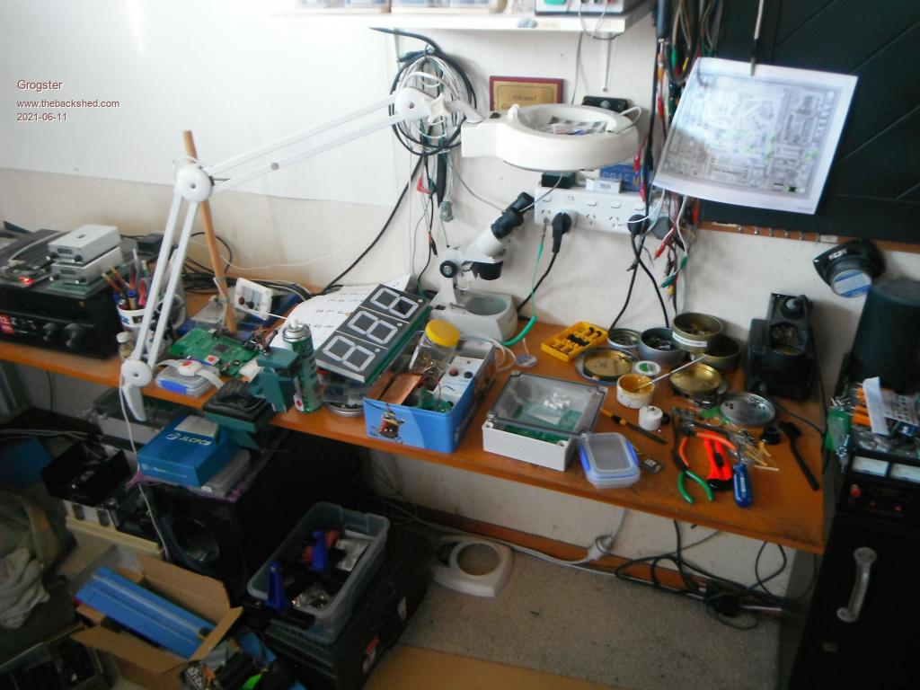 Smoke makes things work. When the smoke gets out, it stops! |
||||