
|

|
Forum Index : Windmills : NEW better Chinese blades, with our help.
| Author | Message | ||||
| sodes Newbie Joined: 26/07/2006 Location: AustraliaPosts: 21 |
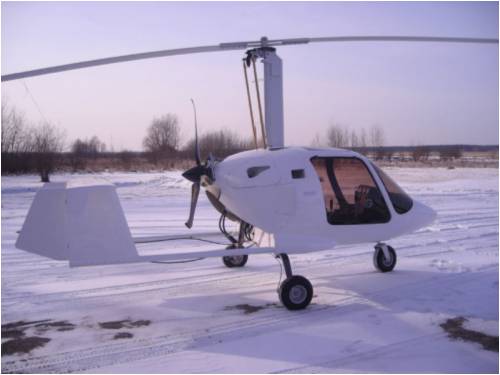
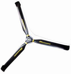
Hi all just reading this article jogged my memory as I was sure I'd seen a wingtip on a prop on some ultralights somewhere. This prop is called the windspoon and is made of carbon fibre and is said to be a very efficient and quiet design would be great to trial a prop just to see how it'd perform, they make these ground adjustable at the hub as well. They're a nice piece of work though! Heres a link http://www.duc-helices.com/anglais/windspoon.htm Sodes 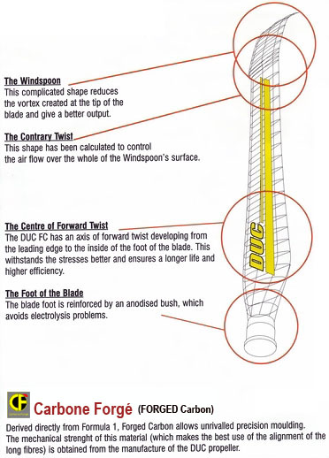
"Do, or do not... There is no try." -Yoda |
||||
| domwild Guru Joined: 16/12/2005 Location: AustraliaPosts: 873 |
Ken, From memory, I posted a link or picture of a large mill with Rutan/Boeing tips on fieldlines.com some time back. So they do get built that way. It looked like a one to two Meg monster mill to me. Taxation as a means of achieving prosperity is like a man standing inside a bucket trying to lift himself up. Winston Churchill |
||||
| Ken. Newbie Joined: 05/10/2008 Location: AustraliaPosts: 13 |
Hi Dom, I havn't seen the pics. Please don't get me wrong...I'm not against the idea of wingtips! I only made the comments to exercise caution with them. The engineers thet designed the big ones you speak of spent a long time testing the aerodynamics in wind tunnels with a bunch of guys in white coats and thick glasses who live and breath this stuff to work it out exactly. None of us have access to the same level of technology.(or R+D funding) I'm all for people "having a go". Can you imagine the guy who first took his drawings of a helicopter to the boss and said "Mate..I think it'll fly"...He musta had balls as big as watermelons!....(excuse the language) But it takes "risk takers" to make advancements. It's just if you're going to make a production model blade, it should be a tried and true design to the best of our abillity..not an experiment. Cheers "Imagination is greater than knowledge" Albert Einstien |
||||
SparWeb Senior Member Joined: 17/04/2008 Location: CanadaPosts: 196 |
Winglets are fine, even for wind turbines, but don't imagine that nobody's thought about this before! A large amount of research has been done on aircraft propellers, wind turbine propellers, helicopter rotor blades, and all sorts of other rotating-wing machines and no doubt the effect of the tip is of interest in each case. US Langley Technical Reports NACA Technical Reports NASA Technical Reports Danish Wind Research Laboratory US military STINET NREL National Renewable Energy Laboratories Don't reinvent the wheel. Read up and you will find the answer. Then again, you can't tell everybody "it's been tried before", they just want to try for themselves. Steven T. Fahey |
||||
| petanque don Senior Member Joined: 02/08/2006 Location: AustraliaPosts: 212 |
Having been involved with gliding I to have wondered about some sort of wing tip variation. I would imagine some important design criteria for a mass produced windmill blade is that It is robust and it is quiet. The current Chinese machines have blades that are neither robust or quiet. After all if it is cheap perhaps the simplest (and cheapest) solution to any loss because of primitive design is to have a longer/bigger blade. While this may be a forum of people who like to tinker I would imagine many people purchasing a commercial unit really want something that they can just forget about. |
||||
| MadRat Newbie Joined: 30/09/2008 Location: United StatesPosts: 21 |
I was more suggesting the winglets for aesthetics. If they change performance at worst it should quiet the tips down. Go Huskers! |
||||
| Gizmo Admin Group Joined: 05/06/2004 Location: AustraliaPosts: 5078 |
OK, an update on the progress Wes and I have made. We are looking at a PVC extrusion, shown below. The PVC section is shown as gray in colour. The extrusion is hollow, with a minimum wall thickness of 2mm. The nose section is thicker at 6mm to allow for wear and impact resistance. The chord length is 160mm. In the middle of the extrusion are guides ( B ) or a hollow tube ( A ) to allow a 22mm diameter steel tube to be fitted, shown in blue. The steel tube will fit along the full length of the PVC blade, and continue a further 100mm or more out the root of the blade, where it will fasten to the turbine hub. The PVC blade will be riveted to this steel tube at several places along the blades length. There will be a molded wing-let that will fit into the blade tip and glued in place, and a cover at the root end of the blade to keep the weather out. 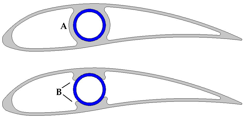
This combination will give us a strong and light blade thats easy to manufacture. Now for the clever bit. By heating the PVC blade to soften it slightly, we can twist the blade around the steel tube. Then just drill and rivet the blades to the tube at the new angles. Or the tubes and blades could be pre-drilled, so just heat and twist to line up the holes. This means we can achieve the best twist and angle of attack for the entire length of the blade. We could see these PVC extrusions sold in lengths, untwisted. Just add the steel tubes, heat with a hair dryer and twist away for whatever TSR you want. Shown below are angles of 0, 10 and 20 degrees, typical angles for the tip to root. Rivets in red. 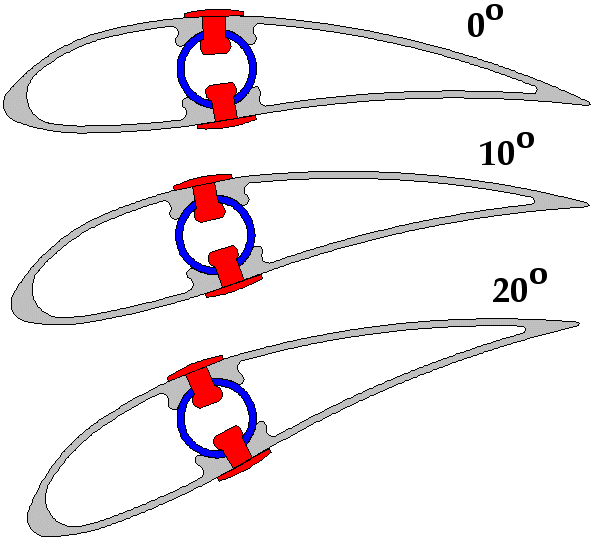
The only problem is the chord length remains constant, although chord length isn't as important as correct angle of attack. What do you think. I've shown two extrusion designs in the top image, not sure how well the full inner circle ( A ) will twist, anyone got experience in bending heated plastics? And how does the profile look? Its a high lift profile, though it does have some drag, so any TSR over 7 might loose out. But it means the blades will have lots of torque. Eager to see what you guys think. Glenn The best time to plant a tree was twenty years ago, the second best time is right now. JAQ |
||||
| dwyer Guru Joined: 19/09/2005 Location: AustraliaPosts: 574 |
Hi Glen and wes I do belive will be great for anyone top adjust the blade to suit however what about patent? Go for it Good on you both Dwyer the bushman |
||||
| philb Regular Member Joined: 05/07/2008 Location: United StatesPosts: 96 |
Nice drawings Glen. I think this has a good chance of working. An improvement might be to use a fiberglass rod or carbon fiber instead of steel. Both will take the bend and flex better than steel. Also, the length can to be cut down by using a circular saw, if need be. I would heat the blade, then put it into a mold to brace it while it rehardens. The "mold" does not have to be extravagant. What length and width do you envision? philb |
||||
| Tinker Guru Joined: 07/11/2007 Location: AustraliaPosts: 1904 |
Great idea Glen. May I suggest STAINLESS steel tubing, 22mm is available (about 1.2mm wall) and often used for boat canopy framing. I would not agree with the above suggestion of using carbon fiber tubing - too expensive and fibreglass rod - too heavy in 22mm size. Tinker Klaus |
||||
SparWeb Senior Member Joined: 17/04/2008 Location: CanadaPosts: 196 |
Now you've really got something that looks nice! I vote against the fiberglass because it's too flexible and against the carbon fibre because it's too expensive. 22mm tubing sounds like a good choice because it's almost equal to 7/8 inch in imperial measure, making the extrusion fit tube available in North America. I did a quick stress calc on a 7/8" tube; steel or a quality stainless tube will be good for a 4foot blade (8-foot prop). You should refine the analysis, and have an engineer study the loads, if you are going to market it as a product. I haven't looked at flexibility, either, so I would test a unit with realistic thrust forces to find out how far back the blade bends - then specify the minimum tower offset for builders to refer to. Also give some thought to the type of rivets you think should be used. Squeezing a rivet into a tube means that you cannot use a solid rivet pounded from both sides. You have to use a "blind" rivet, and many designs, particularly the cheap ones, shake apart easily. They don't install consistently, either. Look into the blind rivets that aircraft home-builders use on their tubular wing spars. Talk to people who maintain aircraft (real ones) and ask them if they can show you the blind rivets they use on aircraft. Then again, there are blind rivets that squeeze so hard, that they could crack your PVC. Choose carefully. While molding sets of wing-tips for the final product, mold a few simple rectangular blocks that also fit into the end - those will be great tools for putting the twist into the blade. Steven T. Fahey |
||||
| MadRat Newbie Joined: 30/09/2008 Location: United StatesPosts: 21 |
How about a slightly thicker top and some cross supports for durability? You do gain a little weight but you protect yourself more from general breakages. You'd hate to have any returns forced upon you by some big brother consumer protection racket, especially from customers that abused them to begin with. And you might suggest epoxy rather than rivets; the metal will expand/contract at a different rate in hot/cold weather and surely crack the blade. I don't know, the round pipe through it just sounds risky from my point of view. 
You could avoid the round pipe altogether and just use a thick cross-brace area, wide enough for an insert through it vertically. They make specialized drill bits for plastic that will not crack it when you tap the holes. You probably are better off keeping the camber (vertical thickness) relatively thin for the aerofoil. The wooden blades of Hugh Piggot tend to be at a 7:1 width to height ratio or better. Another thing Hugh Piggott did was cup the top of the aerofoil like a swoosh to channel air. Go Huskers! |
||||
| Jarbar Senior Member Joined: 03/02/2008 Location: AustraliaPosts: 224 |
Looking good Glenn,to achieve the variance in cord length and to enable the twist to be achieved more easily.Using three different extrusions as depicted in the A profile ie one at 160 one at 120 and one at 80 chord lengths.These sections could be assembled over the tube and then rotated progressivly to the most desirable angles.In between each section or join would be something similar to the proposed wing tip cap.Only it would be a flat strip of pvc strip that would act as mini airfoil that might reduce air sliding up the blade and potentially improving effiecncy.This way different length blades could be assemled with combinations of the best length sections at the best angles.The above cord lengths are only guesstemets. "Creativity is detirmined by the way you hold your tounge".My Father "Your generation will have to correct the problems made by mine".My Grandfather. |
||||
| herbnz Senior Member Joined: 18/02/2007 Location: New ZealandPosts: 258 |
Hi Jabar I like that idea. One other idea that I dont really think is good but it is a seed for thought. Using section B but allow one inside side to be flat rather than locating tube. then if you twisted the section the flat side would slide deepening the curve and change the attack angle while holding it twisted lock in place with rivets. different shapes could be made along the blade length Herb |
||||
| MadRat Newbie Joined: 30/09/2008 Location: United StatesPosts: 21 |
Gizmo- Any updates on your project? Go Huskers! |
||||
| Gizmo Admin Group Joined: 05/06/2004 Location: AustraliaPosts: 5078 |
Yes. The first PVC extrusions have been drawn, they look good. I'll see if I can post the pictures. The blades should be available in up to 2 meter lenghts. Glenn The best time to plant a tree was twenty years ago, the second best time is right now. JAQ |
||||
| domwild Guru Joined: 16/12/2005 Location: AustraliaPosts: 873 |
Glen, Great work! I guess the material would have to be at least uPVC to stay subtle in the sun or perhaps ABS, i think that is what it is called. What sort of a radius or dia. would be required for a single uncogged F&P? Cheers, dom Taxation as a means of achieving prosperity is like a man standing inside a bucket trying to lift himself up. Winston Churchill |
||||
| GWatPE Senior Member Joined: 01/09/2006 Location: AustraliaPosts: 2127 |
Hi dom, uPVC is not ABS. uPVC is unplasticised PolyVinylChloride. ABS is AcrylonitrileButadieneStyrene. An uncogged F&P will probably start with a 2m rotor dia. My mill has shallow angle at the root cord,50mm in 175mm chord and 2.4m rotor, starts in winds a few kph above my AxFx mill. I hope this helps. Gordon. become more energy aware |
||||
| Gizmo Admin Group Joined: 05/06/2004 Location: AustraliaPosts: 5078 |
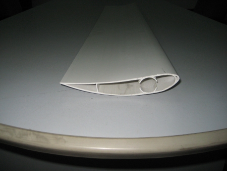
Here are a couple of pics. The ends look a bit rough where they were cut from the extrusion, they need a few mm shaved off to show the true profile. Chord is 160mm, lengths up to 2000mm. They will take a 25mm steel support shaft up the middle. 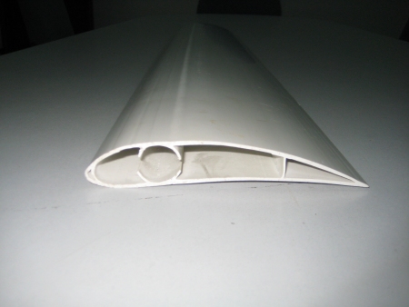
Glenn The best time to plant a tree was twenty years ago, the second best time is right now. JAQ |
||||
fillm Guru Joined: 10/02/2007 Location: AustraliaPosts: 730 |
HI Glenn , Good looking profile , when are the lengths going to be ready for trials ? Will we be able to buy lengths through "The Back Shed" or are they going to a retail outlet ? I would be interested in testing / trialing a few when I get both mills up and running , as you may have seen on the electronics page the dual piclog is working well . BTW do you want me to send your piclog up to you...Regards... PhillM ...Oz Wind Engineering..Wind Turbine Kits 500W - 5000W ~ F&P Dual Kits ~ GOE222Blades- Voltage Control Parts ------- Tower kits |
||||