
|

|
Forum Index : Electronics : Power Jack expert help needed
| Author | Message | ||||
| poida Guru Joined: 02/02/2017 Location: AustraliaPosts: 1419 |
|
||||
renewableMark Guru Joined: 09/12/2017 Location: AustraliaPosts: 1678 |
Ben that Mad controller has an arduino that is optional. It will give you low volt cutout and fans, heat sink temps and their cut out temps etc. What volts do you want the low volt cutout set to? I have mine on 46.5v I'll leave all the other setting the same, just the low volt cutout you'll need to decide on your battery setup. Sorry Poida, looks like I gave you an unexpected job  Cheers Caveman Mark Off grid eastern Melb |
||||
| BenandAmber Guru Joined: 16/02/2019 Location: United StatesPosts: 961 |
you are awesome I so appreciate it If it's okay with you I would rather you pick the voltage I have aGM batteries They are not best suited for solar but they were very cheap 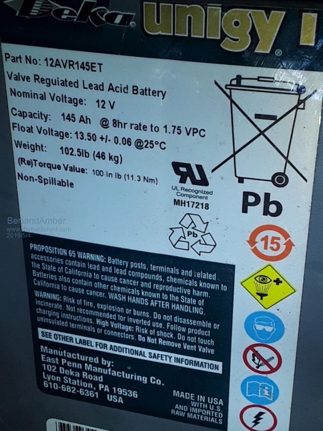 I only have eight of them I was hoping to get 8 more but the guy had already sold the Rest by the time I made enough money to buy them be warned i am good parrot but Dumber than a box of rocks |
||||
renewableMark Guru Joined: 09/12/2017 Location: AustraliaPosts: 1678 |
The nano needs to be set, let me know what cutout volts you want. Keep in mind if you have heavy loads it can temporarily make the volts sag. Cheers Caveman Mark Off grid eastern Melb |
||||
| BenandAmber Guru Joined: 16/02/2019 Location: United StatesPosts: 961 |
46.5 would be great for me if I went with 48 from what I've read that'll be 25% on the battery but I'm really afraid of that voltage sag and no you probably did that for a good reason be warned i am good parrot but Dumber than a box of rocks |
||||
| yahoo2 Guru Joined: 05/04/2011 Location: AustraliaPosts: 1166 |
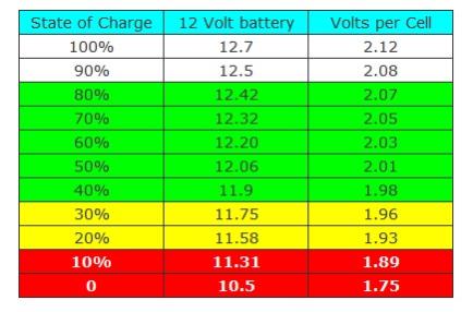 lead acid rule of thumb starting point for AT REST volts. so 46.5 is probably around 25% with newer batteries and a trickle power drain. edit wow image upload hates green jpg sorry. I'm confused, no wait... maybe I'm not... |
||||
| BenandAmber Guru Joined: 16/02/2019 Location: United StatesPosts: 961 |
Thanks Yahoo2 I am very ignorant at these things So i have to go off what I read on the internet yeah I know that's kind of horrible Or I can trust the greats that have a lifetime of experience that's been there and done that I have been doing very well with the second thing there Wow you have been on this form for years Thanks again yahoo2 for your input and the graph be warned i am good parrot but Dumber than a box of rocks |
||||
| poida Guru Joined: 02/02/2017 Location: AustraliaPosts: 1419 |
Further to running the Powerjack inverter from the Madness control board: When running this at 52V, the idle current is 1.5A with the Madness control board. I tested it using the PJ control board and the idle current is 0.38A These 2 tests were using identical choke, toroid and capacitor, producing 230V AC. 0.38A for the PJ control board, 1.5A for Mad control board Why? I had a look at gate drive voltages, at the PJ power board screw terminals, since they are so easy to gank into with short wires for the oscilloscope probes. Here is the low and high side when running under the PJ control board. Yellow is low side, Blue is high side. Nice and clean control, no shoot through. Well, not much anyway. Notice the 2uS dead time. 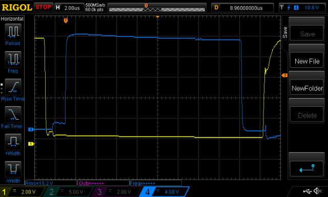 There is some, but since the gate voltage does not rise high enough to conduct for very long, it's not a problem. Here is the same signals, but this time running under Mad control board. 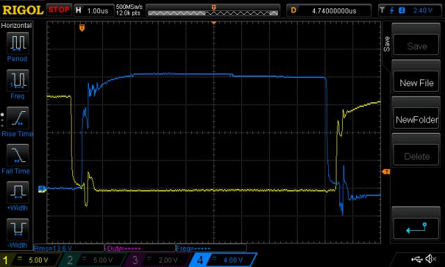 Lots of shoot through. Clear evidence of the oscillations induced by these high energy events too. This is using a 500nS dead time. Increasing this to 2uS will NOT in my opinion alter the degree of shoot through. This is because the shoot through is caused by dv/dt, not poor gate drive timing. I do not recommend you run the PJ inverter with the Mad's control board. I think it's not a good matchup. At this stage I will not send the board to you now. The problem of how to convert a 240V AC PJ to 120V might be easy enough. Maybe you can drive two toroids, one having a 240 output, but small. And one having a 120V output, and huge. Retain the 240V toroid so as to give the PJ control board the needed 240V AC voltage feedback. That is it's only job. Place all the loads on the 120V AC toroid's secondary AND accept that in some cases you will see the voltage droop a little. You plan to put 2-3kW through it. At 50V that's 60A DC and with long shoot through event duration, I think you probably will blow it up. wronger than a phone book full of wrong phone numbers |
||||
renewableMark Guru Joined: 09/12/2017 Location: AustraliaPosts: 1678 |
This might be a silly question but why not buy the power jack control boards that are 120v 60hz? Cheers Caveman Mark Off grid eastern Melb |
||||
| BenandAmber Guru Joined: 16/02/2019 Location: United StatesPosts: 961 |
I don't trust them You're at their Mercy if something goes wrong Then if you can get the part you got to wait for it to take the slow boat here They don't have a power board like mine and they say the new Power Board won't work in mine I'm sure it will because the mainboard and mosfet boards don't look like they've changed it all to me And they try to gouge the heck out of you just a little driver card 30 or 40 bucks but they get you for $29 for shipping and that's the way it is on all the little Parts on the new boards they made them all little modules that make up the big board now which seems like it would be a good thing but it's just so they can gouge you forever a little unreliable piece This is what I've read and experience when I looked into it And one of the best things of all is how cool is it that have a modded inverter the nobody else has that's way more reliable than Factory be warned i am good parrot but Dumber than a box of rocks |
||||
| BenandAmber Guru Joined: 16/02/2019 Location: United StatesPosts: 961 |
I have a way to change the board already have over to 60 hertz Warp speed came up with the solution by changing the crystal oscillator That still leaves me with trying to figure out what kind of feedback Transformer I need to find to switch it out 2 a 120 And once I get all that done I'll have a really unreliable inverter It's no big deal if it's too much of a hassle you guys are awesome and the thought is what counts And I appreciate you guys either way thanks for thinking about me be warned i am good parrot but Dumber than a box of rocks |
||||
| Tinker Guru Joined: 07/11/2007 Location: AustraliaPosts: 1904 |
I can see that BenandAmber are well on their way to build an inverter from scratch and say goodbye to those over rated Chinese inverters with their under size heat sinks. Ben, you have been here long enough to give it a go. There are quite a few posts of building an inverter from nothing up on this forum, rather than using fully assembled control and power boards from various sources and, hopefully, get them to work together. So, all you have to do is re read those posts and avoid the mistakes the original builders made  , this will save a lot of time. You'll get an inverter you can truly say "I built it myself". , this will save a lot of time. You'll get an inverter you can truly say "I built it myself".PCB's are available, you need a decent size heat sink or three, plus the all important transformer. The small parts should be no problem to get. Assuming you have reasonable mechanical skills to accurately drill & tap holes into a heatsink and your soldering is up to scratch, what are you waiting for   . .Klaus |
||||
| BenandAmber Guru Joined: 16/02/2019 Location: United StatesPosts: 961 |
You're exactly right tinker I don't want to be dependent on a company when my inverter breaks down The wait time the inflated parts it don't make much sense to go that way when all you guys have already made something munch better on here And it's just so much fun I have the bug I am addicted or whatever you want to call it I'm building a warpspeed and a nano after I get this 10000w Chinese board and power jack going The 10000 watt I'm waiting on a new toroid choke to come in the mail the one already made just looks tiny in there with tiny wires compared to the Transformer wires As soon as I put the choke in it it is finished the Power Jack I have a new Transformer ready to be wound and now just yesterday I've got the wire ready to wind it with So the only thing I'm lacking on that is a control bored and a couple of the greats on here may already have that took care of for me So I'm not far away from building one from scratch or at least giving it a try I've been looking for heatsinks right now I forget which one of you guys have that absolutely giant heatsink inverter but I plan to copy it but use a nano I do better having two projects going at one time I will be building a warp speed inverter at the same time as building a nano from scratch I have been Gathering the parts for both there's a grid tile on eBay that has giant heatsinks that I may be able to cut down into two it'll probably also have some good caps in it and a few other odds and ends By the way I guess staregazers just a little bit shy The inverters will be for me and him he has his eyes set on the warpspeed inverter I might just have to end up making two of those my little inverter I will probably end up giving to my dad for when the power goes off at his house So all you guys are making a impact on more than just me and it's very appreciated my dad loves to hear about everything you guys are making on here and what's new on the form if he could see well enough and didn't shake so bad he would be building a inverter his self back in the day he used to build all kinds of stuff for CB radios big amplifiers he used to talk to people in Australia from here in West Virginia He wants to be part of it so bad but just can't I have set him up a battery backup system for when the power but it's only 250w and won't start his gas furnace that will soon change when I give him the little inverter that poida the great help me with Sorry for this being so long but besides having to take care of my parents place working on RV and helping Staregazer with all the rentals this is what I've been into and my plans for the near future Thanks everyone for having a positive impact on my life and many others be warned i am good parrot but Dumber than a box of rocks |
||||
| BenandAmber Guru Joined: 16/02/2019 Location: United StatesPosts: 961 |
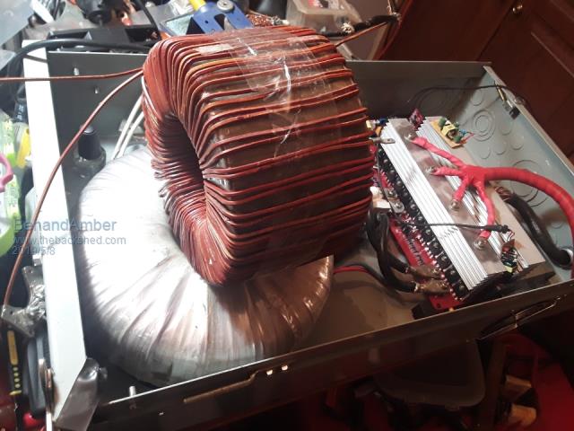 First layer on the power jack Transformer I need to space the wires out a little bit and then on to epoxy I'll be adding a little bit extra hardener and hopefully it'll be drying time to add the second layer Just can't wait so excited get this power jack it up and running be warned i am good parrot but Dumber than a box of rocks |
||||
renewableMark Guru Joined: 09/12/2017 Location: AustraliaPosts: 1678 |
Ben, Poida showed on that previous post that the Mad control board doesn't work well with the Power Jack power board. Mad designed his stuff to work with his own system. I'm afraid you'll need to do a nano board or try and source a power jack one. Maybe just sell it to somewhere that does use 240v? Cheers Caveman Mark Off grid eastern Melb |
||||
| BenandAmber Guru Joined: 16/02/2019 Location: United StatesPosts: 961 |
Thanks for bringing that to my attention I didn't even see it I don't know how I missed it I appreciate all of your hard work and time it took to do all that testing If there's anything I can do to return the favor let me know I would absolutely love to do a nano is that something you guys can get started for me or help me with I can pay you or whatever you want me to do I have no problem paying 4 a control board or control board parts I know it sounds silly but me and my wife both has wanted one of the power jack for the last couple years ever since we first started reading about Oz hacking them we figured we would get on here and make friends with Oz right away It didn't happen that away but I've met some really really awesome people you know the kind that work their butt off for a couple days for you You guys are awesome I've learned so much from you guys and had a really good time along the way if Nano is not achievable for me I guess I'll have to go back to trying to find the right CAD file that Oz has And try to get that sent off have the PCB made and try to find a list of parts I have to get it running somehow and it's my last resort to go with a power jack control board I trust you and poidas opinion on this if you don't think I should do a nano that's fine I'll try to do something else I know nothing about programming and I don't have the stuff to program And if you think a nano is it right for me can somebody please please help me find the right CAD file to send off to a PCB maker for the Oz Control board if I have to go that route I'll just get 10 of them and keep trying till I get it right I've been here long enough to know that this stuff isn't something that you can learn overnight but I can do monkey see monkey do Thanks again for all your hard work and patience with someone like me what goes around comes around and it well be coming back around your way one day I'm sure of it be warned i am good parrot but Dumber than a box of rocks |
||||
| yahoo2 Guru Joined: 05/04/2011 Location: AustraliaPosts: 1166 |
if you want the original Oz board get in touch with Leslie (clockmanfr) https://levivray.com/new-book--make-a-6kw-inverter.php he has a 120v 60 hz control board ready for pcb production. I think! I'm confused, no wait... maybe I'm not... |
||||
| Tinker Guru Joined: 07/11/2007 Location: AustraliaPosts: 1904 |
|
||||
| Solar Mike Guru Joined: 08/02/2015 Location: New ZealandPosts: 1138 |
>> BTW, polyester resin on enameled wire is something I would not recommend. What is the reason for that Tinker, the polyester type is about 1/3rd the cost?? Cheers Mike |
||||
| BenandAmber Guru Joined: 16/02/2019 Location: United StatesPosts: 961 |
Oh my I hope polyester is fine because this is Auto Body fiberglass resin that I am using be warned i am good parrot but Dumber than a box of rocks |
||||