
|

|
Forum Index : Electronics : ozinverter control no sinewave
| Author | Message | ||||
Madness Guru Joined: 08/10/2011 Location: AustraliaPosts: 2498 |
John, You are close to having this one working, you don't get a perfect wave from that initial test. Try running it again without a resistor in series, I use an alligator clip lead for this, it will act as a fuse if needed. You should get a very good waveform with no load then, once you have confirmed that you can put the big capacitors on and run the inverter. That initial test is to confirm you are getting the right signals to the MOSFETs, the results you are getting tells me that is correct. If there was a faulty IR2110 etc then it would not look like what you have got at this point. As the voltage increase at startup the MOSFETs are not able to draw the current needed work perfectly due to the series resistance. If they were clashing with each other it would look very messy and in normal configuration with capacitors and full current available that would destroy the MOSFETs. This is not happening with your inverter. So bypass the resistor, confirm you are getting a good waveform, shut it down add the capacitors, at this stage I would run it via a 10 - 20 amp breaker(AC breaker is okay for this). Before you turn the breaker on charge the capacitors by powering it via the resistor you have been using for testing as the breaker will keep tripping due to the current to the capacitors, once the capacitors are charged up turn on the breaker. Now it may turn on but the slow voltage buildup can crash the EG8010 chip, to reset it leave it powered up and short the 120R 5W resistor to ground on the TIP35C side briefly. Then it should turn on and make power correctly, a 20 amp breaker will trip with a bt over 100W load on the inverter. There are only 10 types of people in the world: those who understand binary, and those who don't. |
||||
| johnmc Senior Member Joined: 21/01/2011 Location: AustraliaPosts: 282 |
Good day Madness, Thanks for the information, I fitted all the 6 * 10000uf main capacitors and also the 4.7uF poly cap had trouble starting inverter after charging the main capacitors through a 100 ohm sesistor. Disconnected the 48v supply then discharged the main capacitors,then switched the inverter on at the control board , zapped the 48v on to the inverter supply  Now the control board soft starts with the on switch or with the reset button 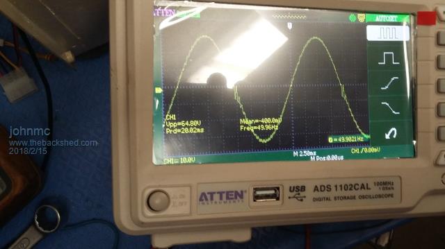 the no load shape of the sine wave. 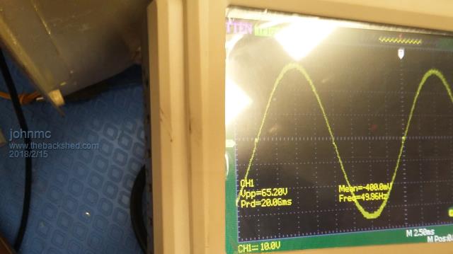 the wave shape with a 500 watt or a 2kw load 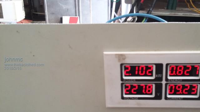 voltage and load for above picture I have learnt that with no main capacitors there is still a sine wave when the inverter is just starting to raise the transformer voltage, then the sine wave develops triangle peaks also blows the 4.7uF poly. When the main capacitors are fitted, this causes the wave form to be corrected as per the pictures The heat sinks are just warm to the touch with no cooling and inverter operating for a short time, with a 2 kw heater load. I still need to connect the cooling fans before I can load the inverter. A very interesting journey so far and much thanks for all the help . cheers john The inverter works nice sine wave johnmc |
||||
Madness Guru Joined: 08/10/2011 Location: AustraliaPosts: 2498 |
That's good news, what is your idle current with no load? should be around 1 amp or less. The inverter not starting after charging up the caps is explained in my previous post. You need to find a different source of the 4.7 caps, something is wrong with the ones you have, There are only 10 types of people in the world: those who understand binary, and those who don't. |
||||
| johnmc Senior Member Joined: 21/01/2011 Location: AustraliaPosts: 282 |
Good day All The continuing tale of enlightenment then total darkness. Yesterday the inverter was working for about 1 hour with a no load current of 1 amp (50 watts) and a clear sine wave from no load to 3kw load . This morning I decided to put the inverter on line alas with the inverter control switched off and through a 50 ohm resistor tried to charge the main capacitors but they continued to draw current. Then tried to zap the capacitors but there appeared to be a dead short between the ovdc terminal and the 48vdc terminal 2 by 63 amp circuit breakers tripped out. The problem is that the high frequency side Fets (12) are shorted circuited they have zero resistance between drain and source The low side Fets (12) appear to be ok My inverter has 24 HY4008 fets and uses clockmans control and power board. What is the maximum HY 4008 fets that the IR2110 (only 2amp) can drive? As I do not know what caused the problem any suggestions would be most appreciated. cheers john johnmc |
||||
Madness Guru Joined: 08/10/2011 Location: AustraliaPosts: 2498 |
I have not had success running 24 MOSFETs off of 2 IR2110's, maybe it is just me. Oztules and Clockman seem to be able to do it. So you will need to talk to them. Most I have run is 16 MOSFETs successfully with that circuit you are using. On my 24FET PCBs I ended up adding Totem pole drivers and that has worked well for me. All mine have been boards of my own design, I can't explain why there is a difference. A very quick check to see if there is a failure on a power board is to measure the resistance between the battery connections, it should be >1 megaohm. There are only 10 types of people in the world: those who understand binary, and those who don't. |
||||
renewableMark Guru Joined: 09/12/2017 Location: AustraliaPosts: 1678 |
Probably another looney idea of mine, but could you increase the power of them by slipping another chip on top? 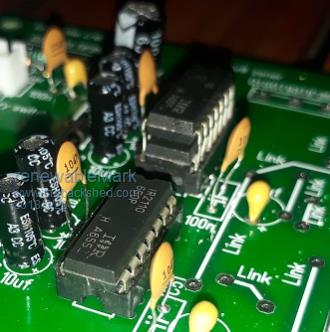 Cheers Caveman Mark Off grid eastern Melb |
||||
| Tinker Guru Joined: 07/11/2007 Location: AustraliaPosts: 1904 |
HaHa, very funny idea which I very much doubt that it will work. Why don't you add a totem pole driver to the IR2110 output? That certainly works for me, driving 24 HY4008's. Klaus |
||||
| johnmc Senior Member Joined: 21/01/2011 Location: AustraliaPosts: 282 |
Good day all Rebuilt the ozinverter from the last blow up with 24 fets (slow learner) . With no large capacitors the system started sine wave had a very slight ripple at the zero cross over point and only the common heat sink slightly warm. Replaced the capacitors, charged the capacitors slowly system started no noise from the system but the sine wave had a marked oscillation at the zero as per the photo 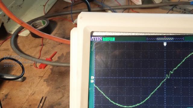 Stopped and started the inverter a few times then  As I started the final time the 8010 gave two blinks and 24 fets died with a load bang . As Maddnes ,Tinker and others have found, they need totem pole drives, as the 2110 by themselves are not up to the task. Waiting for some transistors and will have to make some driver boards. PS still have 40 of the original 100 HY4008 FETS  cheers john johnmc |
||||
Madness Guru Joined: 08/10/2011 Location: AustraliaPosts: 2498 |
Get it working with just 4 FETs and add from there, 16 in total will still give you 5-6KW, I run a total of 12 in one Inverter and it will produce 4.5 KW happily until the Toroid warms up. The squiggle at zero crossing is most likely a choke issue. This is one of the more subdued results I got before adding Totem Pole Drivers. 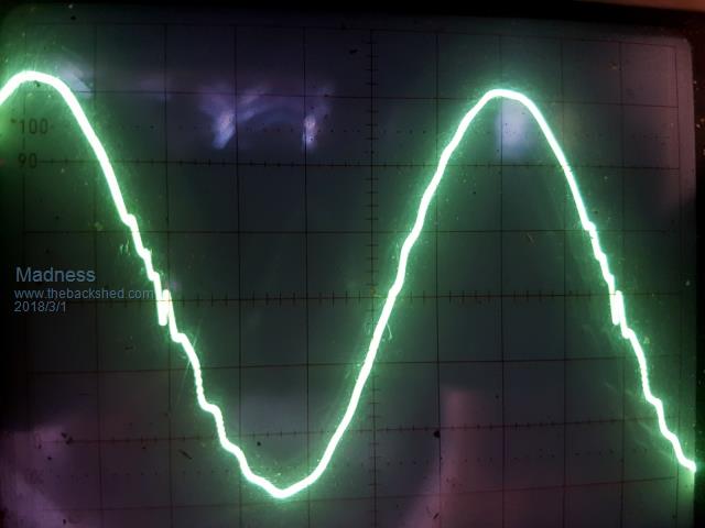 There are only 10 types of people in the world: those who understand binary, and those who don't. |
||||
| tinyt Guru Joined: 12/11/2017 Location: United StatesPosts: 438 |
This is just my opinion and I could be wrong. If the ozcontrol pcb is being used, it is possible that the drivers are being starved. The PCB shows a 120r/5W resistor feeding the TIP35C 12volt regulator (13V zener at the base)from the 48V battery. This TIP35C supplies power to the IR2110. Rough calculation for the voltage drop in the 120r resistor is 48 - 13 = 35 volts. Maximum current that can be supplied by the resistor to the TIP35C is 35/120 = 0.29 amp. Remember, this resistor is also supplying power to the second TIP35C,maybe the chips powered by this second TIP35C are also being starved. Maybe the 100 uF capacitor helps during the PWM drive, I don't know. Maybe scope the IR2110 VCC (pin 3) or the 12-volt line and also the TIP35C collector? |
||||
| noneyabussiness Guru Joined: 31/07/2017 Location: AustraliaPosts: 513 |
Even with 24 mosfets, your looking at 1uf or less gate charge... considering that there are numerous examples working (read 100s at least) i really dont think the 2110 have any problems running them.. I really think your issue is elsewhere... I think it works !! |
||||
Madness Guru Joined: 08/10/2011 Location: AustraliaPosts: 2498 |
Some of us have had problems and the cheap IR2110's may be the culprit. I have been using 18V Zeners the same as Oztules which makes more power available at less current. There are only 10 types of people in the world: those who understand binary, and those who don't. |
||||
| noneyabussiness Guru Joined: 31/07/2017 Location: AustraliaPosts: 513 |
Also agree with Mad, if the 2110's are doing there job properly then there should be no issues... I think it works !! |
||||
renewableMark Guru Joined: 09/12/2017 Location: AustraliaPosts: 1678 |
Those boards were initially made with the 4110 fets, could that possibly have something to do with it? Regarding the 100uf capacitor, when I tested mine they were only coming out at 86uf, which seemed ok, but reckon I'll replace that one just in case. Cheers Caveman Mark Off grid eastern Melb |
||||
| noneyabussiness Guru Joined: 31/07/2017 Location: AustraliaPosts: 513 |
4110's have even more gate charge.. so i don't think it that... I think it works !! |
||||
| noneyabussiness Guru Joined: 31/07/2017 Location: AustraliaPosts: 513 |
Mark, capacity for bypass caps ( not TIMING caps), while important to a degree, the ESR i personally think is more important. .. especially at these levels... your talking 1 ish uf from a 100 uf cap.. walk in the park... however if the ESR is miles out the it will create unnecessary ripple, which would effect it... but again its only 1% of it capacity. I would be looking more at dodgy chips, or damaged traces etc... but only a few of the maybe problems I think it works !! |
||||
Madness Guru Joined: 08/10/2011 Location: AustraliaPosts: 2498 |
I was getting the same with different FETs. I did have a lot less problems when I changed to this supplier. There are only 10 types of people in the world: those who understand binary, and those who don't. |
||||
| johnmc Senior Member Joined: 21/01/2011 Location: AustraliaPosts: 282 |
Good day All On this inverter first build with a 15kw PJ controller Clockman's powerboard, 4110 Fets system worked for 2 odd hours the blew all the 24, 4110 Fets. Second try all Clockman's pcb's same power capacitors,HY4008 Fets same supplier as Madness, looked good for about 2 hours system failed on start up only warning was two very quick flashes from the 8010 control chip before disaster for the Fets Interesting, was the fact that the control PCB and still tested OK with output from the 2110 chips Third build the same as the second build except 18v zeener diode used to increase output drive voltage to the HY4008 Fets, sine wave not as smart as second inverter build, this system appeared to be ok but once again after a few start up the fets destroyed themselves on startup. Can the transformer coupled with the capacitors cause this oscillation which may have an effect on start up? I have built 2, 4 kw inverters using PJ controllers and power boards the first inverter lasted 18 month, the second inverter has been running for the last 12 months it will happily produce 4 kw continuously, but require about 6kw to run the water pump and the air conditioning, for the battery shed and house. This summer the air temperature has been above 42C and the power load for the day has been over 40KW all supplied by solar power. Cheers john johnmc |
||||
Madness Guru Joined: 08/10/2011 Location: AustraliaPosts: 2498 |
My own experience has been not good with the same circuit as Clockman (but not his PCB's) is using, it is working for people but I had lots of issues. Since I changed to use the Totem pole drivers the inverter has worked well, However still not perfect but some of those issues came from other issues with using GTI's and controlling them. I think I have it right now. There are only 10 types of people in the world: those who understand binary, and those who don't. |
||||
renewableMark Guru Joined: 09/12/2017 Location: AustraliaPosts: 1678 |
Where are your 2110 chips from John? Cheers Caveman Mark Off grid eastern Melb |
||||