
|

|
Forum Index : Electronics : 8 KW Inverter Build
| Author | Message | ||||
Madness Guru Joined: 08/10/2011 Location: AustraliaPosts: 2498 |
Clockman I was emailed your post before it was deleted. I have a bank of flat panels and they only get a little dirtier than the rest that I have at 26 degrees. Here we have to put our panels very high, have you seen how high a Kangaroo can jump? Another hazard is flocks of Emus, especially after they have been eating mangoes. That sticky crap really takes a lot to get off once it bakes on.  There are only 10 types of people in the world: those who understand binary, and those who don't. |
||||
Madness Guru Joined: 08/10/2011 Location: AustraliaPosts: 2498 |
The small Inverter I have been working on is not quite complete but it is fully functional now. It has a single core from a 3KW Aero-sharp and the power board has just 12 4110 MOSFETs. I just need to tidy up the wiring and make a lid for it. This is the waveform with 2.4KW fan heater, I have a 5uf cap from an Aero-sharp across the secondary. 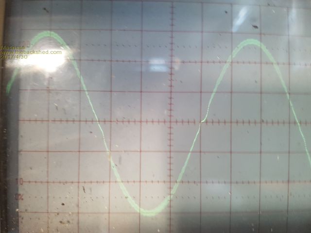 Here is the insides of it and the Arduino fan controller I just made. If anyone thinks this is overkill keep in mind it will always show what the maximum temperatures have been, I think it is worth to have that information. 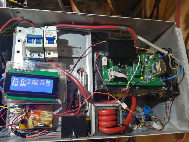 The fan controller displays the current temperature and the highest temp since it was last reset. It is programmed to turn on fans at 45 degrees with PWM minimum set to 15%, so at 45 the fans turn on and stay at 15% until the temperature gets above 46.5 then increases by 10 times the increase in degrees up to 55. 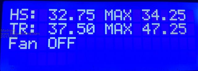 here is how it goes 44.75 off 45 15% 46.5 15% 46.75 16.5% 47 17% etc 55 100% 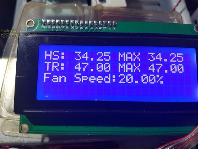 There is a sensor on both the heatsink and the Toroid, however, the heatsink is much cooler. Today we had a cool 24 degrees ambient temp so it took 17 minutes from a cold start to get up to the point where the fans started with the fan heater load. Here is the Arduino code if anyone is interested. /* YourDuino.com Example: Multiple DS18B20 Temperature Sensors Displayed on 4x20 character LCD display DS18B20 Pinout (Left to Right, pins down, flat side toward you) - Left = Ground - Center = Signal (Pin 9): (with 3.3K to 4.7K resistor to +5 or 3.3 ) - Right = +5 or +3.3 V terry@yourduino.com */ /*-----( Import needed libraries )-----*/ // Get 1-wire Library here: http://www.pjrc.com/teensy/td_libs_OneWire.html #include <OneWire.h> //Get DallasTemperature Library here: http://milesburton.com/Main_Page?title=Dallas_Temperature_Control_Library #include <DallasTemperature.h> // Wire (I2C) Library #include <Wire.h> // LCD Library #include <LiquidCrystal.h> #include <LiquidCrystal_I2C.h> /*-----( Declare Constants )-----*/ /*-----( Declare objects )-----*/ // set the LCD address to 0x27 for a 20 chars 4 line display // Set the pins on the I2C chip used for LCD connections: // addr, en,rw,rs,d4,d5,d6,d7,bl,blpol /*-----( Declare Constants and Pin Numbers )-----*/ // Data wire is plugged into port 9 on the Arduino (can be changed) #define ONE_WIRE_BUS 9 // NOTE: No ";" on #define #define pwm 10 /*-----( Declare objects )-----*/ // Setup a oneWire instance to communicate with any OneWire devices // (not just Maxim/Dallas temperature ICs) OneWire oneWire(ONE_WIRE_BUS); // Pass address of our oneWire instance to Dallas Temperature. DallasTemperature sensors(&oneWire); // Start the LCD display library LiquidCrystal_I2C lcd(0x27, 2, 1, 0, 4, 5, 6, 7, 3, POSITIVE); // Set the LCD I2C address float HSmax; float TRmax; float FANtemp; float tempTR; float tempHS; float fanspeed; float fanpwm; float fanpercent; /*-----( Declare Variables )-----*/ // Assign the addresses of your 1-Wire temp sensors. // See the tutorial on how to obtain these addresses: // http://arduino-info.wikispaces.com/Brick-Temperature-DS18B20#Read%20individual // WP 1 DeviceAddress Probe01 = { 0x28, 0xFF, 0xA8, 0xCF, 0xA0, 0x16, 0x3, 0xB4 }; // "4" DeviceAddress Probe02 = { 0x28, 0xFF, 0x35, 0x9D, 0xA0, 0x16, 0x4, 0xB3 }; // "5" //DeviceAddress Probe03 = { 0x28, 0x9A, 0x80, 0x40, 0x04, 0x00, 0x00, 0xD5 }; // "4" Again for test //DeviceAddress Probe04 = { 0x28, 0x10, 0xA4, 0x57, 0x04, 0x00, 0x00, 0xA9 }; void setup() /****** SETUP: RUNS ONCE ******/ { //------- Initialize the Temperature measurement library-------------- sensors.begin(); // set the resolution to 10 bit (Can be 9 to 12 bits .. lower is faster) sensors.setResolution(Probe01, 10); sensors.setResolution(Probe02, 10); // sensors.setResolution(Probe03, 10); // sensors.setResolution(Probe04, 10); //---------------- Initialize the lcd ------------------ lcd.begin(20,4); // initialize the lcd for 20 chars 4 lines, turn on backlight lcd.setCursor(0,0); }//--(end setup )--- void loop() /****** LOOP: RUNS CONSTANTLY ******/ { sensors.requestTemperatures(); // Send the command to get temperatures lcd.clear(); // Reset the display lcd.home(); lcd.backlight(); //Backlight ON if under program control // Print our characters on the LCD // NOTE: Line number and character number start at 0 not 1 lcd.setCursor(0,0); //Start at character 0 on line 0 lcd.print("HS: "); { tempHS = sensors.getTempC(Probe01); if (tempHS == -127.00) // Measurement failed or no device found { lcd.print("Error"); } else { lcd.print(tempHS); HSmax = max (HSmax, tempHS); lcd.print(" MAX "); lcd.print(HSmax); } lcd.setCursor(0,1); //Start at character 0 on line 1 lcd.print("TR: "); { tempTR = sensors.getTempC(Probe02); if (tempTR == -127.00) // Measurement failed or no device found { lcd.print("Error"); } else { lcd.print(tempTR); TRmax = max (TRmax, tempTR); lcd.print(" MAX "); lcd.print(TRmax); } } { FANtemp = max (tempHS, tempTR); lcd.setCursor(0,2); if(FANtemp <45 ) { analogWrite(10,0); lcd.print("Fan OFF "); } else if(FANtemp>=45) { fanpercent = (10*(FANtemp-45)); fanpercent = constrain(fanpercent, 15, 100); fanpwm=((fanpercent*255)/100); analogWrite(pwm, fanpwm); lcd.print("Fan Speed:"); lcd.print(fanpercent); lcd.print("%"); lcd.setCursor(0,3); } } delay(500); }//--(end main loop )--- /*-----( Declare User-written Functions )-----*/ }// End printTemperature //*********( THE END )*********** There are only 10 types of people in the world: those who understand binary, and those who don't. |
||||
oztules Guru Joined: 26/07/2007 Location: AustraliaPosts: 1686 |
That little unit will power most small to med off grid houses without air conditioning. It is not a toy... I like it. My new boards are on their way from China, so should be here in the next week or so. They will use 4 x hy4008, and coupled with a decent tranny will power the house just fine and easy. The control board will have the current limiter on board, and they will do 20kw surges without a problem.... thats enough for me now. I don't really like the algorithm for your fan..... as I don't see why you would let the thing get any where near 55c if you can avoid it. I would prefer to have a tight ramp... depending on your weather I guess, but i won't let mine get over 40c if possible. I will start the comparator at 35c, and it will virtually never get to 45. I don't take a lot of notice of transformer temp, particularly now i am following your lead with the enamel primary. I use the heat sink temp to drive both fans. The heat sink is easy to keep cool, the tranny not so easy, but not important... I want cold capacitors if at all possible, and cold fets if I can... the big tranny will look after itself.... probably up to 55c in heavy long use. The tranny is in a separate compartment, so does not contribute it's heat profile to the power electronics. Looking forward to your using this thing in the field to see how well it performs. ........oztules PS I did not prototype the boards, so fingers crossed I didn't screw it up  Village idiot...or... just another hack out of his depth |
||||
Madness Guru Joined: 08/10/2011 Location: AustraliaPosts: 2498 |
It is very easy to shift the temperature settings, from what I have seen toroids are supposed to good for up to 100 degrees in most cases, some to 130. The heatsinks are quite a bit bigger than what you use also so they do stay quite cool. The temperatures on the LCD show HS for heatsink as you no doubt guessed anyway, so far the HS has stayed at least 10 degrees cooler anyway. I could stick a sensor on one of the caps to see what is going on there. I will try setting it to start at 35 and get to 100% at 40. The 140mm fans I have shift a lot of air even at 50% PWM, even 15% gives a good breeze. There is Arduino software now that runs on my phone so I can use it to reprogramme it off the phone. You live in an ice box, this last summer here it would have been running all day long blowing 35+ degree air through it before trying to cool down anything. I know you are not a fan of them but the Midnite CC's I have run at 55 degrees, anything under that and the fans turn off. It is extremely rare to hear of anybody having failures with them and when they do it usually lightning or something external that causes it. This Inverter will mainly be used for PWM controlled diversion to the HWS at least until I get the big Inverter running with a cleaner waveform. If I run the PWM to the HWS it causes the GTI to take it's bat and ball and go home for sulk until it sorts itself out. Are you planning to post your circuit with the new over current shutdown? BTW "PS I did not prototype the boards, so fingers crossed I didn't screw it up " Have you heard of O'Shannessy's law? He said Murphy is an optimist! There are only 10 types of people in the world: those who understand binary, and those who don't. |
||||
oztules Guru Joined: 26/07/2007 Location: AustraliaPosts: 1686 |
It takes no effort to keep the heat sinks at 45c, rather than a minimum of 55c... note this from https://en.wikipedia.org/wiki/Electrolytic_capacitor#Lifetime "This rule is also known as Arrhenius rule. It characterizes the change of thermic reaction speed. For every 10 °C lower temperature the evaporation is reduced by half. That means for every 10 °C lower temperature the lifetime of capacitors doubles. If a lifetime specification of an electrolytic capacitor is, for example, 2000 h/105 °C, the capacitor's lifetime at 45 °C can be ”calculated” as 128,000 hours—that is roughly 15 years—by using the 10-degrees-rule." So, midnight can do what they want, but I would prefer to err on the side of cool.... as it does not seem to hurt to have the fans running at very low speeds most of the time to achieve this.... so the simple act of using 35c cooling quadruples the lifetime of the caps... in other words crap caps at 35c will probably outlast good caps at 55c..... eg 7 years to 30 years... so why not? Yes if the boards work as expected, it will all be published.... the boards that is... don't do circuits  Not sure I understand this...... " If I run the PWM to the HWS it causes the GTI to take it's bat and ball and go home for sulk until it sorts itself out. ".... what is the pwm causing the problem.... from the midnight? ..........oztules Village idiot...or... just another hack out of his depth |
||||
Madness Guru Joined: 08/10/2011 Location: AustraliaPosts: 2498 |
The Midnite CC has a function called "Waste Not", what it does is send a PWM signal to a SSR when the panels are generating more power than is required. This starts once Absorb voltage is reached, this rapid turning on and off of the SSR to the hot water causes extra distortion in the sine wave out of the Inverter. The GTI does not like this, Once I get this Inverter setup properly I will play around with the capacitance on the big toroid as per Warpspeeds posts. The big Inverter has been running now for more than 2 weeks without an issue apart from this PWM thing upsetting the GTI. I look forward to seeing your PCB when you confirm all is well. There are only 10 types of people in the world: those who understand binary, and those who don't. |
||||
Madness Guru Joined: 08/10/2011 Location: AustraliaPosts: 2498 |
I have set it now to start at 35 degrees full speed at 35, I will see how that goes. if(FANtemp <30 ) { analogWrite(10,0); lcd.print("Fan OFF "); } else if(FANtemp>=30) { fanpercent = (20*(FANtemp-30)); fanpercent = constrain(fanpercent, 5, 100); fanpwm=((fanpercent*255)/100); analogWrite(pwm, fanpwm); lcd.print("Fan Speed:"); lcd.print(fanpercent); lcd.print("%"); lcd.setCursor(0,3); } There are only 10 types of people in the world: those who understand binary, and those who don't. |
||||
| yahoo2 Guru Joined: 05/04/2011 Location: AustraliaPosts: 1166 |
I like your new smaller version Madness, that is ticking all the boxes. that is my favorite size for an inverter. I have been meaning to do some tests to see if I can get a latronics 3.5kw and a fronius primo GTI with a export control meter to play nice on an off grid system unfortunately I sold all the bits and pieces before I got a chance. I am looking at this little beauty and thinking it would probably be very suitable for my test setup. I'm confused, no wait... maybe I'm not... |
||||
Madness Guru Joined: 08/10/2011 Location: AustraliaPosts: 2498 |
I have a 5KW GTI I would like to get working off grid also but it does not have a transformer setup like the Aero-sharps. Initial testing I did with it was a fail, it just popped the breaker as soon as it tried to connect. Yet it works fine with the grid. The smaller inverter was a lot less work to build, the toroid only had to have one set of windings removed and the primary added, that only took a few hours to do the whole job. I have 2 4.5 KW Trace inverters that could be run as one if I had the right hardware to add to it. One 4.5 on it's own was just not quite big enough for us that is why I have gone for the bigger 8KW for running the house. But if we did not use electric ovens, AC, dishwasher the smaller one I have built would do a very good job. The previous post I should have said it starts at 30 and fans are at the maximum at 35. I am going to change this as the Toriod triggers it when the heatsinks are still well under 30. I am thinking I will change the code so it has different thresholds for the 2 sensors. There are only 10 types of people in the world: those who understand binary, and those who don't. |
||||
| Tinker Guru Joined: 07/11/2007 Location: AustraliaPosts: 1904 |
Mad, the current limiter that is shown on the schematics I posted a while ago works very well with the IR2110 drivers. It can be set to whatever surge limit one wants and turns off lightning fast if it is exceeded. look here I very much doubt that oztule's is much different. In any case, we could challenge him to say so if he does not do schematics. Klaus |
||||
oztules Guru Joined: 26/07/2007 Location: AustraliaPosts: 1686 |
Here is the relevant part of the board.... NOT tested until they turn up. 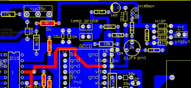 It is supposed to turn off the 2110 and the current pin of the 8010. This allows the use of all the led output signals that the 8010 does to the front panel. Reset is done by shorting the 120r power resistor on the input... it does 2 things. First if your input voltage rises too slow, the 8010 locks up ... so it allows a hard fast reset, and you can also reset the o/current event. It is a a bit quicker than Tinkers as the damping is less. I'm betting it works out of the box..... or I am in for some disappointment I guess ......oztules Here are the gerbers for better definition perhaps 2017-05-01_120900_CAM_for_CONTROL.zip Village idiot...or... just another hack out of his depth |
||||
Madness Guru Joined: 08/10/2011 Location: AustraliaPosts: 2498 |
Thanks Oz for the PCB image, I have ordered the SCR's, will be good to hear if the circuit works as you expect. I have managed to get the Zeversolar 5KW TL5000 GTI operating with my OGI, before it was tripping the 20A breaker as soon as it tried to connect the AC, I tried it with a 63A breaker and it worked. This Inverter was a bargain from the local tip shop, cost me $5 looks brand new even came with the wall mount for it. 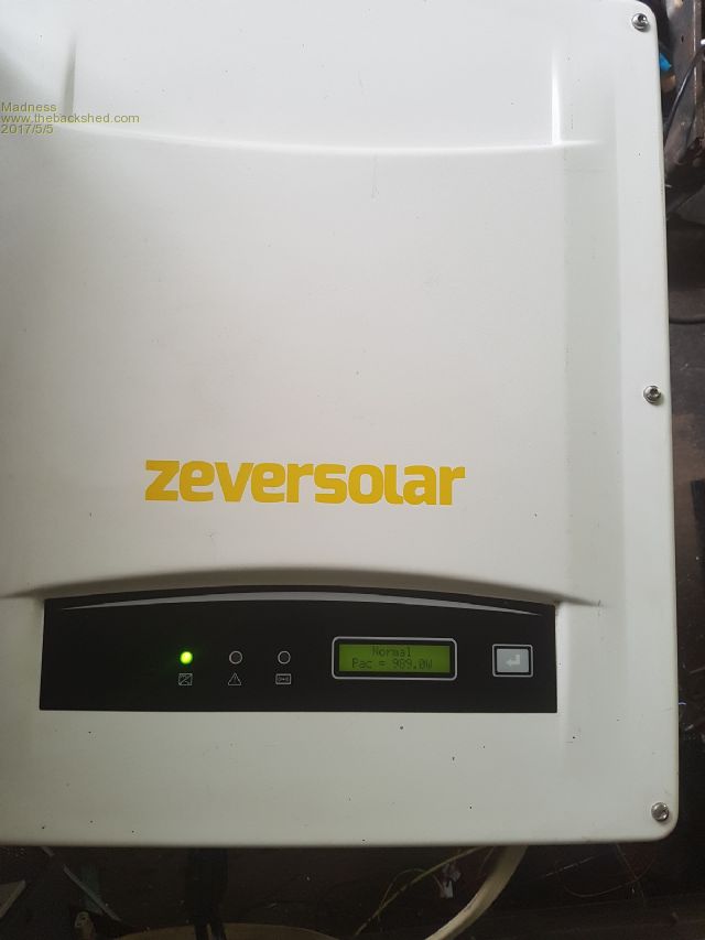 It is connected to a single bank of 1500W of panels here it is just after 9AM so power output is to be expected. 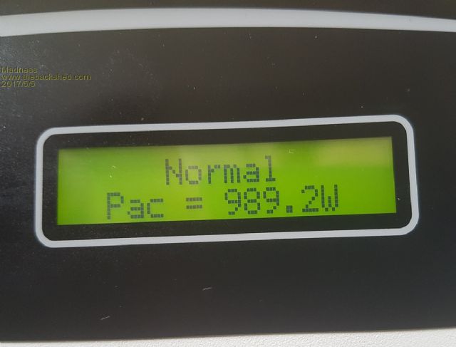 Next week I plan to setup the 5KW of 2 year old 250W panels I just bought for $700 with this GTI. I had considered doing it with DC but it involves a lot of wire, the GTI only needs two pairs of cable and has dual MPPT. There are only 10 types of people in the world: those who understand binary, and those who don't. |
||||
oztules Guru Joined: 26/07/2007 Location: AustraliaPosts: 1686 |
Wow.... 5kw and a GTI for $700......  Boards should arrive next week I hope. ......oztules Village idiot...or... just another hack out of his depth |
||||
Revlac Guru Joined: 31/12/2016 Location: AustraliaPosts: 1026 |
Good to see this working for you Madness, I look forward to trying out my GTI with 2KW of panels. I didn't expect it would need such a large breaker. Cheers Aaron Cheers Aaron Off The Grid |
||||
Madness Guru Joined: 08/10/2011 Location: AustraliaPosts: 2498 |
20 was not quite enough for it and the next size I had was 63. Actually seems to run better than the Aero-sharp, makes no noise and the OGI is quieter as well. Oztules said something before about ones without transformers but this seems to be doing just fine. Not sure why it was at the tip, it is showing 1760 KWH's total that it has made. Will soon see how it goes with 5KW's shoved through it. 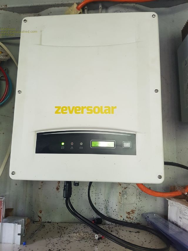 There are only 10 types of people in the world: those who understand binary, and those who don't. |
||||
| Mulver Senior Member Joined: 27/02/2017 Location: AustraliaPosts: 160 |
So I was unwinding my second 3kw Aerosharp toroid and was thinking..... Could we wind the secondary like this?? Line up give or take ~4x ~1.6mm dia enamel wires, wind it up into one cable. Then Maybe then epoxy and mylar tape around as you come around for the second or third pass.(or heat shrink it??) I'm thinking this for primarily 2 or 3 stack cores?? Have i got unwinding delusion or is this a possibility? Shane |
||||
| Tinker Guru Joined: 07/11/2007 Location: AustraliaPosts: 1904 |
So I was unwinding my second 3kw Aerosharp toroid and was thinking..... Could we wind the secondary like this?? Line up give or take ~4x ~1.6mm dia enamel wires, wind it up into one cable. Then Maybe then epoxy and mylar tape around as you come around for the second or third pass.(or heat shrink it??) I'm thinking this for primarily 2 or 3 stack cores?? Have i got unwinding delusion or is this a possibility? Shane IMO, the the secondary has too many turns for for this idea to work. You would need to twist wire some 40m long, a bit awkward. Then, you will take more core room to wind that bundle back on neatly, resulting in a smaller hole for the primary winding. But you could do what I was doing, winding two in hand at once. You will need an about 600mm diameter 'reel' to store the wire side by side on while you wind two in hand at once. I did describe that method in my toroid build somewhere. Klaus |
||||
Madness Guru Joined: 08/10/2011 Location: AustraliaPosts: 2498 |
I tried the bike rim idea first off but quickly changed to using the small spool so you can unwind against the core. Keeping the wires parallel will save space. The secondary has much higher voltages, especially when you get near completion of the turns and are against the beginning so insulation is critical. You could try a test of a few metres and see how it goes on. Twisting the length you need may be a handful to get that right. Another thing to watch is if you can do it in one layer, twist a short length of the 3 or 4 wire together that you plan to use. Measure the diameter of the twisted wires and calculate the circumference of the inside of the core less the radius of your wire bundle. Just calculated it from when I did it with 75mm inner diameter and 98 turns that I used on a double core you would need to have your wire 2.4 mm in diameter to do it in one layer which just is not going to happen. There are only 10 types of people in the world: those who understand binary, and those who don't. |
||||
| Mulver Senior Member Joined: 27/02/2017 Location: AustraliaPosts: 160 |
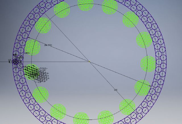 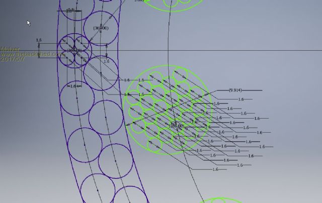 Just a quick mock up this morning, 2 stack toroid, 4 in hand (could be a handful) secondary, 114 turns (2 x 57) Primary 26 in hand, 16 turns. |
||||
Madness Guru Joined: 08/10/2011 Location: AustraliaPosts: 2498 |
Nice CAD work, what software do you use? There are only 10 types of people in the world: those who understand binary, and those who don't. |
||||