|

|
Forum Index : Electronics : building an Inverter from scratch
| Author | Message | ||||
oztules Guru Joined: 26/07/2007 Location: AustraliaPosts: 1686 |
I find that the transformer regulation as poida notes is very very good. Even when I am testing the current o/load at over 15kw,the regulation seems to be exceptional. In fact the 70 and 80 amps@240v I see on the clamp meter during 5hp induction motor start up is accompanied by an instant start of the motor, no lag or stutter or struggle, it is every bit as good as on the mains.... so it did not sag at all under massive load. There is no discernible light flicker or dimming inside the house when 3kw jug or pump motor or any other load starts, regardless of the loads at the time.... ie no loads.... then whomp, another 2-3kw ... or running at 2-3kw...then another 3kw... seems to make no difference. So I am struggling with the current quandry that seems to be talked about. Regulation is second to none that I have witnessed thus far.... there is just no light flicker, led or flouro... I think mad eluded to this previously too. So I don't think that is the problem here.... I don't have a clue what it may be, as I don't have this problem, but I think VFB is not it. Poida, very interested in your arduino efforts, and will try to follow your progress... even though the 8010 is cheaper than the cheapest arduino, it would be nice to have total control. So if you can get it as good as the 8010, I will have to get into it for real. ..........ozules Village idiot...or... just another hack out of his depth |
||||
Madness Guru Joined: 08/10/2011 Location: AustraliaPosts: 2498 |
Hi Klaus, Have you had a win with the TC4452 drivers? From what I can see(I may be wrong) is that they are not designed to drive high and low side. The circuit you have posted shows the output of the IR2110 connected to the input of the TC4452, this input is designed for 2 - 5 Volts, in this case is it would be getting a minimum of 12V and possibly up to battery voltage + 12 V depending on the potential difference between the bridge and the output of the IR2110 high side output. I can get them running fine without a transformer but as soon as the transformer is connected it fails on the high side. I know you are using a separate isolated power supply on your high side. I have just used the same bootstrap supply circuit but made a second one to supply the TC44552's. Essentially the same as the circuit you posted but with the second 12V supply. There are only 10 types of people in the world: those who understand binary, and those who don't. |
||||
| Warpspeed Guru Joined: 09/08/2007 Location: AustraliaPosts: 4406 |
[quote]From what I can see(I may be wrong) is that they are not designed to drive high and low side. The circuit you have posted shows the output of the IR2110 connected to the input of the TC4452, this input is designed for 2 - 5 Volts, in this case is it would be getting a minimum of 12V and possibly up to battery voltage + 12 V depending on the potential difference between the bridge and the output of the IR2110 high side output.[/quote] The input to the TC4452 is basically a mosfet gate with a gate threshold of about +1.5v and an +18v max rated gate voltage. This enables to work directly from 3V powered cmos, or 5v powered TTL, (both of which have about a 1.5 logic threshold) or higher voltage powered cmos with up to 18v supply. Driving it from an IR2110 isolator fed from +12v will be fine. Here is a direct cut and paste from the data sheet : [quote]The TC4451/TC4452 inputs may be driven directly from either TTL or CMOS (3V to 18V). Moreover, 300 mV of hysteresis is built into the input, providing noise immunity and enabling the device to be driven from slowly rising or falling waveforms.[/quote] http://ww1.microchip.com/downloads/en/DeviceDoc/20001987C.pdf Cheers, Tony. |
||||
| Tinker Guru Joined: 07/11/2007 Location: AustraliaPosts: 1904 |
Mad, The TC4452 worked fine with transformer loads <60W, my power source limit I guess as I used a DC/DC boost converter to up my bench supply to 56V DC. What I did notice is the soft start appears to be much smoother by not using that charge pump high side supply idea - but I may have just imagined this. More testing tomorrow, with the battery bank I hope if a few other modifications I made pass the bench supply test. Klaus |
||||
| Warpspeed Guru Joined: 09/08/2007 Location: AustraliaPosts: 4406 |
Quite understandable Klaus. The IR2110 has individual undervoltage shutdown on both upper and lower drivers, and the charge pump may need to crank over a few times before it starts up, if the initial drive pulses are extremely narrow. Cheers, Tony. |
||||
| azhaque Senior Member Joined: 21/02/2017 Location: PakistanPosts: 117 |
Tinker Great work. I want to clone but also want to take it a step further by adding a microcontroller. What should be added. I can immediatly think of external comms for sharing data about volts amps degC etc. What else do u think will be needed. I will use EAGLE for the PCB. azhaque. |
||||
Madness Guru Joined: 08/10/2011 Location: AustraliaPosts: 2498 |
If you are adding a microcontroller the only thing I would change on the circuit above is perhaps the means to turn it off if it gets too hot or battery voltage drops too low. Everything else should be independent of the Inverter circuit. You can sense temperature, current, volts and control fans with sensors that don't change the circuit above. I have planned to do the same but have not got that far. My plans were for sensing and data logging the following Heatsink Temp Cap temp Toroid temp AC current AC voltage Data logging with the ability to do charts would be good to see with temperature and power in particular. There are only 10 types of people in the world: those who understand binary, and those who don't. |
||||
| azhaque Senior Member Joined: 21/02/2017 Location: PakistanPosts: 117 |
"Heatsink Temp Cap temp Toroid temp AC current AC voltage" So it is 3 temp inputs,1 dc volts and 2 AC volts (one being voltage proportional to AC current). USB for external comms so that data can be put on IoT. An ATMega8 should do it. azhaque |
||||
Madness Guru Joined: 08/10/2011 Location: AustraliaPosts: 2498 |
I was planning to use a Ethernet shield with a micro sd card. There are only 10 types of people in the world: those who understand binary, and those who don't. |
||||
| Tinker Guru Joined: 07/11/2007 Location: AustraliaPosts: 1904 |
Some results of my capacitor in parallel with the toroid secondary test. Thanks Tony for your excellent explanation how to do it. Anyway, there was a marked increase of the audio oscillator wave level at 75Hz when I placed a 3uF capacitor. I did use a 1K resistor to attenuate the oscillator output. Now, working backward with that calculator posted earlier I get a secondary inductance of 1.5 Henry. Could that be right? I think my earlier measurements with the little inductance meter were compromised. It is not shielded and I measured right next to my running power inverter for my house. I guess there is plenty of electromagnetic interference near these things. I will see if I can repeat that resonance result tomorrow with a proper mounted capacitor rather than one dangling off test leads. Poida did some interesting tests on this subject. Klaus |
||||
| Warpspeed Guru Joined: 09/08/2007 Location: AustraliaPosts: 4406 |
Entirely possible Klaus. From memory the 1.5Kw inspire I tested quite a long time ago used a 5uF and resonated at 82Hz, that works out to 0.753 Henries. A few extra turns and more steel in the core could quite easily double that. Cheers, Tony. |
||||
| Tinker Guru Joined: 07/11/2007 Location: AustraliaPosts: 1904 |
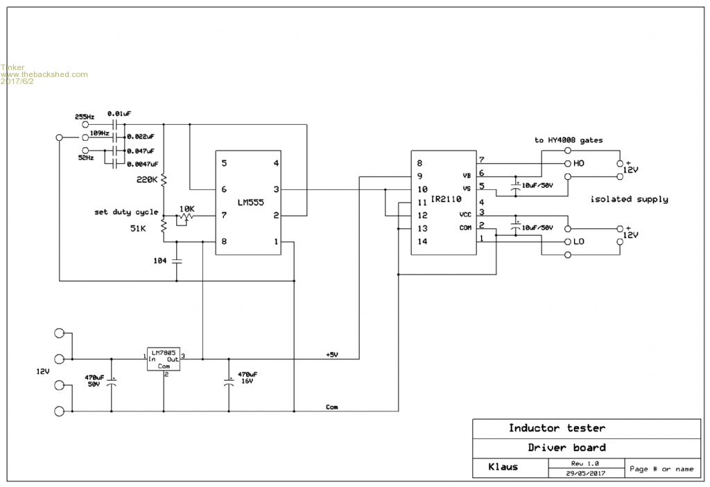
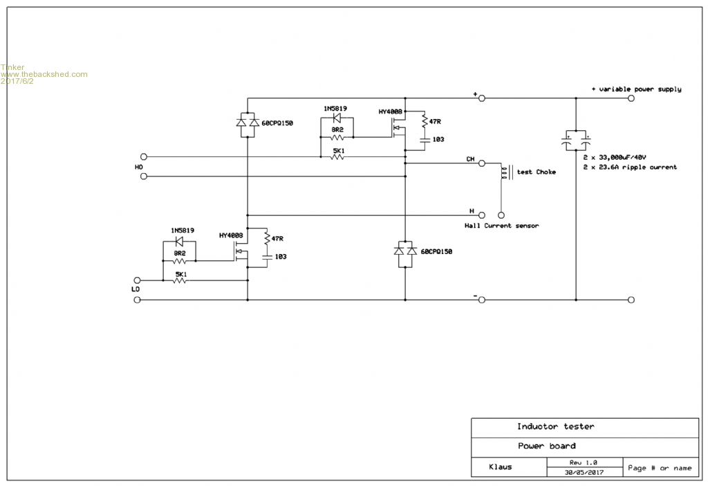
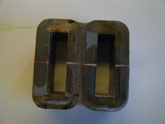
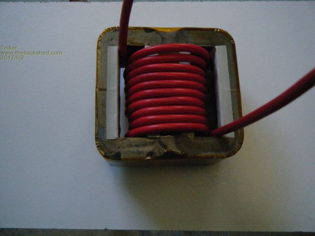
A little progress on my inductance saturation tester. The PCB's (2 off) are made but I'm still waiting for the power schottky diodes. Here are the schematics, much simpler than Solar Mike's but then this is just a basic test unit.  And the power board:  This is my test inductor core:  Its made by epoxying together two of the large inductor cores found in the 3KW Aerosharp inverter. I used 2mm thick plywood between the two cores. The air gaps are about 1.6mm. 10 turns of test coil wound on:  Hopefully I will soon find out at which AT that core saturates. On another matter, while testing the gate pulse generating board I realised this also makes a neat way to test those IR2110's that experienced the magic smoke from the exploding mosfets. I had my fair share of that magic smoke and usually ditched the gate drivers as well since I did not know if they survived. There were a few still on my bench and plugging them in, then shorting the gate drive with a 1K resistor (no mosfets), its easy to see on the scope if there is a neat square wave on the hi and lo side drive output or rubbish, as happens with a busted driver chip. Klaus |
||||
Madness Guru Joined: 08/10/2011 Location: AustraliaPosts: 2498 |
Hi Klaus, I found Oztules method of no caps on the power board and resistance in series with the power supply very good for testing control boards and the driver chips. If something is amiss you get a bad waveform but no smoke escapes. Have you tried the TiP41/42 drivers yet? mine has been running faultlessly for close to 2 months now. There are only 10 types of people in the world: those who understand binary, and those who don't. |
||||
| Tinker Guru Joined: 07/11/2007 Location: AustraliaPosts: 1904 |
Hi Gary, Yes, I did try oztules method of testing and it always seems to work well but the resistor limits any power drawn from the inverter. My problems started when I tried to draw more power. I have made the boards for the TIP41/42 drivers but will first investigate a decent choke that does not get saturated when more than one light bulb is powered from the inverter. If that cures the sine wave 'wiggles' then I think a working inverter follows. Perhaps my design just has to have a perfect wave form, the 90mm sq primary & 10mm sq secondary on the toroid have a lower resistance than anybody else's toroid. So any current limiting on mine is far less than on other build I have seen here. It all rests on the choke to prevent runaway conditions. Klaus |
||||
Madness Guru Joined: 08/10/2011 Location: AustraliaPosts: 2498 |
I am very interested in how you go with the choke, the waveform I am getting is not perfect apart from little or no load. Your Toroid is similar to mine in the amount of copper in it as you know. Since I have added the 5KW GTI my OGI very rarely gets much more than 3KW load on it. There are only 10 types of people in the world: those who understand binary, and those who don't. |
||||
| Warpspeed Guru Joined: 09/08/2007 Location: AustraliaPosts: 4406 |
Looking really good there with the choke Klaus. Your saturation tester really needs to have a fairly widely adjustable frequency range with a fixed 50% duty cycle. Not sure why there are just three fairly close switched frequencies provided. Something like 20Hz to 10Khz continuously variable might be more like it. If the "on" time ever exceeds 50% its going to go bang. The current will ramp up fine, but will be unable to fully ramp down back to to zero because there might be insufficient time for it to do so. The current will then quickly ratchet up a bit higher each cycle in an uncontrollable way until something fails. A 555 is fine, but please use a divide by two flip flop on the output for safety. Pin 4 of the 555 (reset) needs to be tied high. The 4046 VCO solution is a lot nicer and uses no more parts. Cheers, Tony. |
||||
| Tinker Guru Joined: 07/11/2007 Location: AustraliaPosts: 1904 |
Thanks Tony, your input is, as always, very much appreciated. Its just a simple 555 circuit I found on the net. I thought since the working frequency of the toroid is 50Hz the choke should be tested at the same?? Anyway, its a simple matter of putting smaller capacitors to raise the frequency but I'm curious why it should be continuously variable? I did not know about the danger of the greater than 50% 'on' time. The circuit will easily adjust to a little less than 50%. Else a divide by 2 flip flop chip. I did not have a 4046 phase locked loop nor am I familiar with this chip. Bu I can get one from Altronics and experiment. I'm sure Solar Mike does not mind me flattering him by copying his circuit. Klaus |
||||
| Warpspeed Guru Joined: 09/08/2007 Location: AustraliaPosts: 4406 |
I suggest you get the 4046, it already has the necessary flip flop inside, and its much easier to use for this than a 555 anyway. For testing unknown chokes, or any chokes that can vary widely in size and inductance, we need a variable voltage source, and a continuously variable ramp up time. A wild guess might place your new choke at roughly around 100uH (we shall see). If so, it will ramp up at one amp for each applied volt over 100uS. Maybe ramp up to 30 amps with 30 volts applied over a 100uS ramp up time. That is just an example, 100uS up and 100uS down requires 5Khz. If we wanted to ramp up to 90 amps it is going to take three times as long, say 1.67 Khz. If we dropped the test voltage down to only five volts, it ramps six times slower than at thirty volts. So our 100uH choke requires 1.67Khz/6 = 278 Hz to reach 90 amps. So you can see, depending on what you are testing, or how hard you wish to push it current wise, we might need a fairly wide choice of frequency. Its a lot easier to do if your voltage control knob and frequency control knob both cover a suitably wide range all in one continuous sweep. Cheers, Tony. |
||||
| Tinker Guru Joined: 07/11/2007 Location: AustraliaPosts: 1904 |
Hmmm Tony, I think you convinced me that I have to put on my study hat. Now, where did I put it??  I did get a couple of 4046 chips today, they were not expensive. So its just a question of making another little PCB for it. Expect more questions when its finished as that "ramp up" thing still has me puzzled. I thought we are feeding the gate drivers with a square signal, either the mosfet is on or off at a 50% duty cycle. So what am I missing? Perhaps its just something that my 70 year old brain has forgotten long ago  . .Klaus |
||||
| Warpspeed Guru Joined: 09/08/2007 Location: AustraliaPosts: 4406 |
I am not seventy yet, but in a shockingly few months I will be. Actually I am quite looking forward to reaching middle age. The gate drive is a square wave, but when both mosfets turn on, the current through the choke ramps up. When both mosfets are off the current (through the choke) ramps back down back through the diodes. As long as we give it enough time to completely ramp back down to zero we are sweet, a 50/50% duty cycle always allows that with a bit to spare. If we turn or mosfets back on too soon before the current has fallen completely down to zero, it again begins to ramp up BY THE SAME AMOUNT, and as we started off with something greater than zero it ramps up to a higher peak than it did the first time. This keeps on going with each successive ramp up peaking higher and higher until something really bad happens. The current just runs away on you. So an adjustable duty cycle is a bit dangerous if it can be set to go over 50% on. That is why the 555 could be a fearsome device. With the 4046 we get a flip flop for free, and when we increase the on time, the off time also increases in direct proportion, so we need never worry about the runaway condition. Its one less thing to go wrong. Cheers, Tony. |
||||