
|

|
Forum Index : Electronics : building an Inverter from scratch
| Author | Message | ||||
| Tinker Guru Joined: 07/11/2007 Location: AustraliaPosts: 1904 |
Thanks poida, I'm afraid my old brain locks up trying to digest all of what you write. You do have some nice equipment, I wish I had a CRO that can display such nice traces. Mine is a 1990's model  . .So, using an Arduino to control the VFB is beyond me. I gotta get this thing running reliably in a much simpler way. And it apparently can as oztules keeps telling us. I did experiment with feeding a low voltage pure AC (transformer isolated from mains) into the VFB input. The inverter did run but I could not get the output voltage range adjustment I wanted. Rather than experimenting with different dropping resistors before the potentiometer, I replaced the bridge rectifier I had before to feed DC to the VFB. Perhaps you could tell me if this bridge rectifier (mini 1A type) is a poor choice and I should use 4 individual hi speed (or schottky) diodes? Klaus |
||||
| Warpspeed Guru Joined: 09/08/2007 Location: AustraliaPosts: 4406 |
Great stuff Tinker. It seems these Chinese mosfets are a bit of a mixed bag with no real quality control or factory testing. Unfortunately if you have a dozen or more fitted to an inverter and one gives up, it is likely to instantly kill all the others without any obvious cause. Building a mosfet torture test rig is an excellent idea, run them pretty hard for a few hours or days at elevated voltage and temperature. Then just use the survivors. All this is difficult enough to do without having to suffer multiple failures due to garbage sub standard failure prone parts. A cheap part that fails is no bargain. Poida, excellent work on the feedback. It looks like the optimum solution might be a low voltage isolation transformer, a resistively loaded full wave rectifier, followed by an efficient low pass filter. If the sampling period is so very short, that might be a problem if there is any noise or any other disturbance on the feedback voltage. Something like a phase controlled light dimmer, or fan speed controller, might feed some voltage glitches back into the inverter that might have some pretty dramatic effects if they occur right during the feedback sampling period. Cheers, Tony. |
||||
Madness Guru Joined: 08/10/2011 Location: AustraliaPosts: 2498 |
I use a SSR controlled by a charge controller to divert power to the hot water system once the batteries reach absorption voltage. This is done with PWM, so the SSR is turning on and off rapidly. My old Trace inverter makes lots of noise when this is going on, however the Oz inverter is hardly affected at all by this. It is very obvious in lights they flicker quite a lot with the Trace and barely noticeable with the Oz Inverter. There are only 10 types of people in the world: those who understand binary, and those who don't. |
||||
| poida Guru Joined: 02/02/2017 Location: AustraliaPosts: 1418 |
Tinker: for sure it's best to use the EGS002 for control. It does a good job when modified appropriately. As far as rectifier choice goes, I would take the EG8010 documentation as the guide. They use high speed diode (FR107) but any high speed diode will do so long as it can take 1000V. UF4007 diodes are at Jaycar for $2 ea. and are overkill for the job. Warpspeed: I agree that the narrow sample window is likely to have consequences. Notice there is a two stage LP filter in the design shown on page 9 of the EG8010 document. To reduce but not eliminate the effects of transients on the AC load and therefore introduced transients in the sort of DC feedback we need to low pass filter better than first order RC filters. The trick is to permit changes in Vfb that correspond to maybe 5Hz through to the controller (to allow it to maintain the AC voltage setpoint) but stop anything changing faster. I have been playing with 2 and 4 pole Butterworth filtering of Vfb in my prototype. Not a lot to report so far. On an other note can I add my 2c on the recent discussion on mosfet switching speeds that seems to conclude "faster is better"? There is an effect called dV/dT switch on. This happens when the drain sees a fast change in voltage. The Gate:Drain capacitance also sees this voltage change and so it causes a voltage rise on the gate, sufficient to cause the mosfet to conduct to some degree. dV/dT switch-on is caused by the gate being driven too fast. I have seen this in my two inverters (the prototype and a commercial board obtained from aliexpress) It is not due to too small or too long deadtime. One reason I built the prototype was to see the effects of deadtime on dV/dT and there is none. I could vary the DT from 0.5us to 2us continuously via a trim pot while seeing gate voltage and DC bus current on the oscilloscope. There was no reduction of this problem with changes to DT. Why care about this anyway? The full bridge design means that when a mosfet is off we want it to really be off. The dV/dT switch-on means cross conduction will occur. When under large loads, I wonder how on earth our inverters survive when they are shorting the DC bus 20,000 a second, albeit for 20ns or so at a time. wronger than a phone book full of wrong phone numbers |
||||
| Warpspeed Guru Joined: 09/08/2007 Location: AustraliaPosts: 4406 |
Poida, I do not have an EG8010 board, or the instructions that go with it, or even one of these inverters to play around with ! Really I am on the outside looking in with all of this, my own home brew sine wave inverter is not even PWM. But I do have a background in power electronics, and may be able to come up with a few suggestions and ideas others may like to try out. I agree that the feedback system definitely needs a low pass filter with a fairly steep roll off and good phase response, and that a two stage (four pole) active filter would be the way to do that. The choice of a 5Hz cut off frequency also sounds excellent, you obviously know exactly what you are doing. With regards to switching speed, the TC4452 driver has independent pull up and pull down output pins, so its very easy to adjust turn on and turn off switching speeds quite independently. I still feel the biggest problem trying to get multiple large die mosfets to switch directly from a wimpy driver is having too slow switching rather than too fast, and the TC4452 is a step in the right direction. Another issue is the inherent source drain diodes that have relatively slow recovery times, and too fast turn on switching can create some problems there too. Most people here will not have a sufficiently good oscilloscope to really be able to see any of this. Cheers, Tony. |
||||
| Tinker Guru Joined: 07/11/2007 Location: AustraliaPosts: 1904 |
Thanks, I use most of what's on the EGS002 schematic on my own board. I started by using the modified EGS002 board but after killing a few of them (the drivers on them go kaputt when the Mosfets expire)I got sick of waiting for more ordered ones to arrive. On my board the IC's are on sockets so easy to exchange. High speed diodes it is then for the rectifier but, really, 1000V specs for diodes at a 12VAC secondary seems to me way overkill. There are lower voltage UF400? diodes. I'll look into more filtering of that DC, presently there is only a 100 Ohm series resistor after the pot and 0.1uF ceramic capacitor to GND. Your suggestion what extra components might help are welcome. Klaus |
||||
Madness Guru Joined: 08/10/2011 Location: AustraliaPosts: 2498 |
I think he is working with the example circuit in the EG8010 data sheet which has no transformer so the diodes are running at the output voltage of the Inverter. FR107 Diodes are rated for a range of 50 - 1000 Volts, which makes me ask what happens when they are run in a 12V circuit? There are only 10 types of people in the world: those who understand binary, and those who don't. |
||||
oztules Guru Joined: 26/07/2007 Location: AustraliaPosts: 1686 |
Interesting Mad......They conduct at .6v, by .8v they can carry their max 1 amp.... and by 1.6v they can carry a surge current of 20 amps..... I think they will work just fine... but their test circuits uses a 50v source when measuring the reverse recovery time... in the pdf.?????.... but... With .6v turn on, it certainly is not a 50v zener anyway. ...........oztules Village idiot...or... just another hack out of his depth |
||||
| Warpspeed Guru Joined: 09/08/2007 Location: AustraliaPosts: 4406 |
You don't really need ultrafast or special diodes for this, although some ordinary slow rectifier diodes can misbehave if run at little or no load. So the trick is to fit a load resistor directly across the dc output of the bridge rectifier. It will not take much, only a very few milliamps perhaps to fix any diode related problems. But check the rectifier output waveform with an oscilloscope, and fit a load resistor to make the waveform nice and clean and text book correct. If you use a low voltage transformer (highly recommended) common small signal diodes such as 1N4148 will work just fine. These little fellows have ratings a lot higher than most people expect. http://www.vishay.com/docs/81857/1n4148.pdf And they are faster than most "fast recovery" diodes anyway. They behave very well for this type of application, and they are cheeep. Cheers, Tony. |
||||
Madness Guru Joined: 08/10/2011 Location: AustraliaPosts: 2498 |
Here is some very useful reading about MOSFETs. Particularly pages 11 & 12 about gate drivers, I have the TC4452's working on test with 4110 FETs, today I will be connecting a transformer and seeing what the result is. So far I am getting very good waveforms on the gates and they are at higher levels than the IR2110s alone. I have added separate power supply with a TIP35 same as the control board just to power the TC4452s and 4.7uf Tantalums across the chips. PCB's are barely bigger than a stamp. 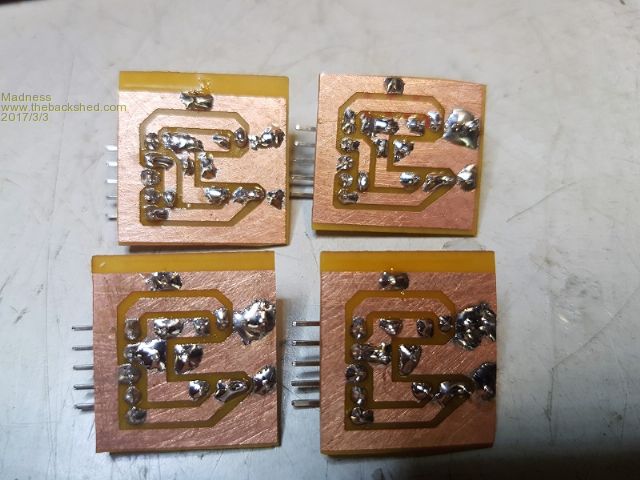  There are only 10 types of people in the world: those who understand binary, and those who don't. |
||||
| poida Guru Joined: 02/02/2017 Location: AustraliaPosts: 1418 |
Tinker: here is my Vfb setup. This probably will not be suitable for your situation. Do you have an oscilloscope? I really recommend using one when playing with home brew inverters. If you do not have one, I suggest the Rigol DS1054Z which can be hacked to 100Mz and run all optional add-ins. I can help with hacking (or check out EEVBLOG) Cost is $570+GST. Geez they've gone up a bit since when I got mine. I took a 9V unregulated plugpack out of it's plastic case. This gives me a ready made 240V AC -> 9V DC sub system. The diode bridge uses 1N5391 diodes and a 10uF cap. Then I divide this nominal 9V output with 470R and 270R resistors with the 270R connected to ground and divided output at the join of 270R and 470R resistors. V div is 270/(470+270) * 9V = 3.3 Nominal at 240V AC I intended this to be connected to an Arduino ADC input which can take 0 - 5V so 3.3V is nice with plenty of headroom if I let the inverter run a bit high. The EG8010 needs 3.0V so you would use a trim pot to give 3V. The divided 3.3V is then fed into a low pass RC filter, 75K resistor and 33nF cap This smooths things a fair bit. Right at the Arduino ADC input pins I have another LP filter with 100R and 0.1uf. This still permits a little AC ripple. (why two filters? I want to investigate the effect of noise etc on Vfb and the PID loop control behavior with the prototype Adrduino controlled inverter. I have a long pair of wires conveying Vfb past the FET bridge picking up masses of EMI. This is by design.I want to see how much filtering is needed. And how much EMI mucks up the control loop...) Warpspeed suggests 1N4148 diodes and I agree these will be fine for the purpose. https://www.jaycar.com.au/1n4148-1n914-signal-diode-pk-5/p/ZR1100 cost $0.60 for 5 Thanks Madness for the supurb document linked above. That is a keeper. 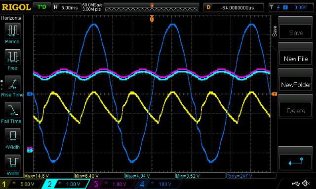 above shows (Yellow) the "9V" output with huge ripple due to too small 10uF cap Pink is after the 75K, 33nF LP filter Light Blue is after the 100R 0.1uF final filter I use 2 filters for my particular needs in testing EMI noise effects upon the control loop. Finally for those interested in dV/dT turn-on I show this: 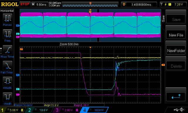 Yellow is DC bus current Dark blue is AC output Pink is low side HF gate drive Light Blue is high side HF gate drive. Note how the low side gate easily gets to 4V which is well within the gate threshold voltage of the IRF3808 mosfets I am using. When this happens there is a small peak in DC bus current. This is dV/dT turn-on. I'm not sure about how much of this is interesting to you all. Please tell me to STFU if it's too much. wronger than a phone book full of wrong phone numbers |
||||
| Warpspeed Guru Joined: 09/08/2007 Location: AustraliaPosts: 4406 |
The problem with having a 10uF capacitor after the rectifier is that it will respond quickly to sudden voltage increases, but not so quickly to sudden voltage decreases. If you reduce the capacitance, or load down the output, the ripple value increases. Cascading filters just adds to the overall delay. The best "technical" solution to all this is to just run a straight rectifier with light resistive loading. At every zero crossing, the output waveform from the rectifier goes right down to zero. Then follow that with a very sharp cut off low pass filter that has a good flat frequency response up to several Hz, then drops like a rock to have very high attenuation at the 100 Hz ripple frequency, and above. You will get dead smooth dc out, but any disturbance in amplitude will give a pretty rapid step change in the dc output level, both increasing AND decreasing. This will have the fastest response with the least amount of ripple and noise on the output. Cheers, Tony. |
||||
| Solar Mike Guru Joined: 08/02/2015 Location: New ZealandPosts: 1138 |
This is all very interesting, so possibly a single chip switched capacitor low pass filter with 8th order Butterworth response could possibly be used here with a HF cutoff approx 10hz. Last time I used something like this was a good 15 years ago, they seem to have improved somewhat since. This chip just requires a single cap to set the cutoff frequency. MAX7480 |
||||
| Warpspeed Guru Joined: 09/08/2007 Location: AustraliaPosts: 4406 |
I had not thought of using a switched capacitor filter, but looking at that MAX7480 that would definitely be well worth a try. The higher the cut off frequency can be placed, the faster the inverter feedback voltage will be able to respond to sudden load changes in both directions. I played around with all this many years ago, but my filter back then was just two stages of the usual op amp active filter. A "real" filter with steep slope and good phase response should make a considerable difference. Cheers, Tony. |
||||
| Solar Mike Guru Joined: 08/02/2015 Location: New ZealandPosts: 1138 |
Even though using the switched cap filter is perhaps a trivial bit of extra componentry, its not overkill complexity is it, I mean OZtules and others have their inverters working ok without it, running all sorts of loads like welders etc. If indeed the EG8010 takes a fast voltage sample once each 50hz cycle, then as long as the rectified 12 vac output sample has a capacitor with a small load to discharge it, any low level 100hz ripple present on the sample feedback DC wont make any difference as it will be sampled at the same time each cycle, so would still react to voltage changes in both directions. In fact is a seperate 230/12 volt transformer required at all, why not wind a dozen turns of fine insulated wire direct on the main toroid transformer to get an isolated voltage sample. ?? Cheers Mike |
||||
| Warpspeed Guru Joined: 09/08/2007 Location: AustraliaPosts: 4406 |
I suppose it depends on how benign your inverter load is. If its a constant clean steady resistive load, almost anything will work. If there is a lot of noise coming back, from say sparking commutators in power tools or voltage spikes from phase controlled equipment, the sampled voltage waveform at the inverter will need at least some very basic filtering, which is pretty easy. If you just sampled directly on the raw ac mains waveform, you may be in trouble. The difficult part is often large voltage sags from motor starts such as refrigerators and air conditioners. Or voltage surges when a huge load is suddenly switched off. Even that may not matter too much if you don't mind flickering lights. The two above requirements are not really compatible or easily met. About the best you can do is design a proper low pass filter for the feedback. But almost anything will work. As for a few turns on the transformer, that depends what you see there. How much constant amplitude PWM is still there, and how much pure sine wave ? Probably mostly sine wave, but where does all the PWM finally disappear ? Is there more low pass filtering needed after the transformer ? If this low pass filter on the output seriously effect the output voltage regulation, it would be better to sample right across the inverter final ac output rather than anywhere else. Cheers, Tony. |
||||
| Tinker Guru Joined: 07/11/2007 Location: AustraliaPosts: 1904 |
Great guys, keep that thread going, 30 pages already & counting  . .I made some more adjustments to the inverter control with regard to the VFB voltage source that is being discussed at present. Here is the latest updated schematic: 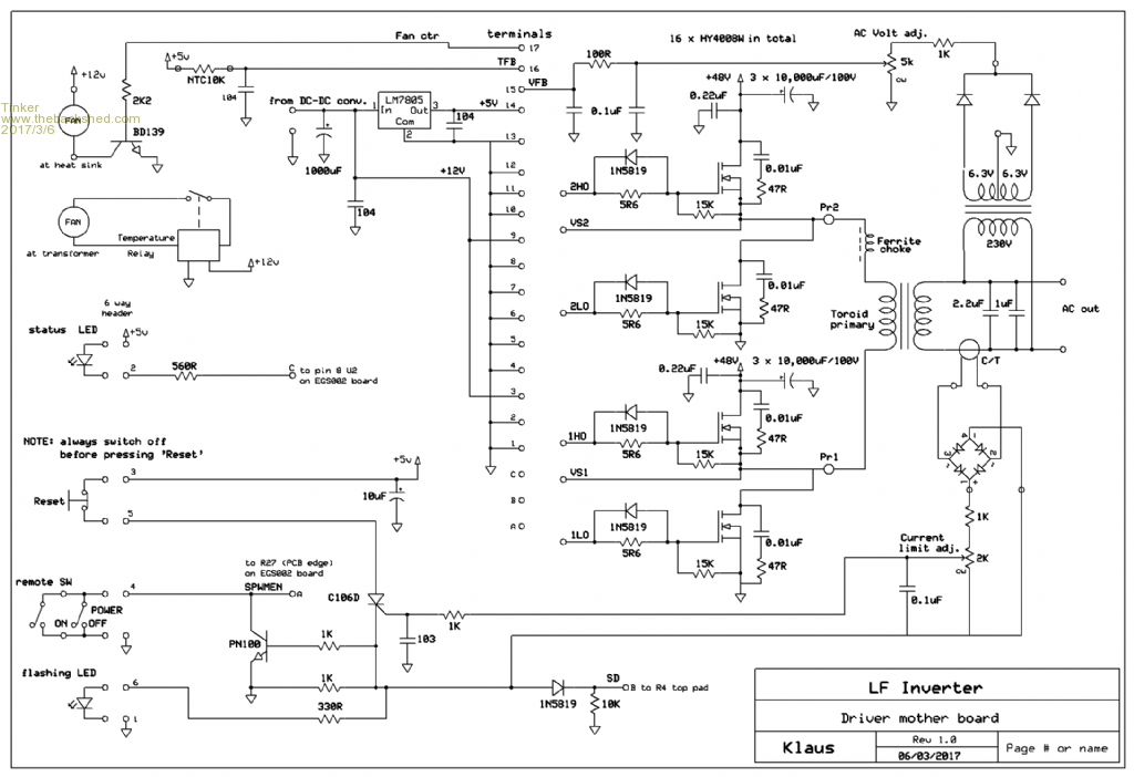 You'll notice I used a center tapped secondary transformer to get the VHF voltage. This give me a nice 100Hz ripple that goes down to 0.1V and with a peak of 3.1V. The diodes are UF4004 BTW. Now, while I could not manage to kill a Mosfet all day while experimenting with this I wonder if its *really* necessary to add lo pass filters. The ripple has a 20KHZ 'ringing' very short spike on it, about 1Vpp. Would not a notch filter be more suitable to get rid of that - if it needs to be got rid of in the first place. I'll continue trying to get it to misbehave. Here is a pic of my new test rig, it works so well I will recommend it for newbi inverter builders: 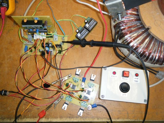 Notice I made a box that mimics the inverter control switches, very handy. A close up pic: 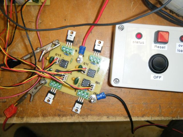 It can easily accommodate TO220 Mosfets by splaying the outside legs a little. Once I have a batch of chips that passed my soak test - I'm using 65V DC which is about 10V higher than my battery bank - Load testing will commence. Very gently this time  . .Lastly, my ring ferrite primary choke. Wound 4 in hand of 20mm sq cable. It makes no noise at all while doing my no load experiments. 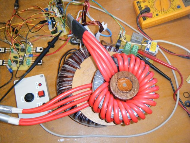 Klaus |
||||
| Warpspeed Guru Joined: 09/08/2007 Location: AustraliaPosts: 4406 |
Some really nice workmanship there Klaus, very well done ! Cheers, Tony. |
||||
| poida Guru Joined: 02/02/2017 Location: AustraliaPosts: 1418 |
I tried getting Vfb from a few turns around the main toroid transformer. The transformer was something like 1.7V/turn so I needed 7 or so turns, then rectified and divided it down to 3V DC. Beauty, no need for all this extra stuff just to get Vfb I thought. Voltage feedback control did work fine, but the problem was output voltage of the inverter was porly regulated over varying load conditions. I could set it correct for low loads or set it correct for high loads but not for both. I think it's a result of poor transformer load regulation. Once I attached a small power supply transformer (9V AC, etc..) to the 240V AC output of the main toroid things became well regulated under all loads. It's the best way to do this. see https://www.electrical4u.com/voltage-regulation-of-transformer/ wronger than a phone book full of wrong phone numbers |
||||
| Warpspeed Guru Joined: 09/08/2007 Location: AustraliaPosts: 4406 |
Yes, pretty much as expected. Cheers, Tony. |
||||