|

|
Forum Index : Electronics : Inverter PCB’s
| Author | Message | ||||
Madness Guru Joined: 08/10/2011 Location: AustraliaPosts: 2498 |
I need to test the current sensing with a hall effect sensor as per the attached PDF for the GTI regulator. This will allow current limiting based on battery current to protect the battery and monitor State Of Charge. 2018-05-25_161610_HA2020-300A-150mA_en.pdf There are only 10 types of people in the world: those who understand binary, and those who don't. |
||||
renewableMark Guru Joined: 09/12/2017 Location: AustraliaPosts: 1678 |
I'll be getting a couple of the GTI boards when you have them ready, no need for the little inverter though. Cheers Caveman Mark Off grid eastern Melb |
||||
| mason Regular Member Joined: 07/11/2015 Location: CanadaPosts: 86 |
Madness, when will the charge control boards be available? |
||||
oztules Guru Joined: 26/07/2007 Location: AustraliaPosts: 1686 |
Primary is just half the normal 48v stuff. An analog system is a good thing for those that don't want to dabble in digital. Digital is not better by definition, but just a different way of doing the same thing... generally it is more stable as it is not real time. Digital gives us more simple control, but also gives us more room for failure. Analog just works, digital should work, and with more room for adjustment via programming. Analog will always return a value dependent on real world conditions, digital returns something resembling real world... then we do something with it. As we have all found, the fan control with analog works perfectly well, and it should do with digital too. Analog is real world , and only as good as the circuit is. Digital is only as good as the programming is. For understanding, analog is probably the best, as what we see is what we get. Our recent disagreement is about how we program, not what is programmed. In remote installations, understanding is key to empowerment, and fuzzy logic instead of pid control is understandable to the novice, as it is unlikely that the novice understands what is in the derivative and integration steps of a proportional integration derived outcome. Nor will they likely understand the interactions with a unibus system with digital sensors hidden in a library. Most who try arduino code will be able to understand fuzzy logic, and digital read of a pin. Both can yield the same results as the library driven derivative. Yes I understand both. I can program in assembly as well, and talk to the chip in machine code... but this means nothing in the real world. I am not afraid of micros.... but I am light years behind Poida and his ilk, make no mistake. I know my limitations at present.... but I can make a micro do what I need it to do in most circumstances.... spwm not included here. Now thats out of the way I think that your idea has merit. like most of them do. It is probably just as well to redesign the fan control board, to incorporate the uvlo. We need the 12vdc for the fans, and thats not on the current control board iteration anyway.... and I'm not sure it should be either. So simply empowering any of the 3 spare comparators with the appropriate time constants will probably be perfectly adequate for the purpose required. The feedback loops will give us the required hysterisis, and or lock up. This can be fed to the temp pins via opto , and that will then not interfere with the temp control at all.... ie on uvlo, empower the otpo... short the pins. Tinker also had a resolution to the same problem somewhere here. It wasn't my preferred solution, but another solution none the less. There is nothing wrong with the nano solution either, but from my point of view, programming with libraries which we don't understand the workings of, is against the thrust of this inverter... something anyone can build simply.... isn't that what drew you all to this project in the first place? Thats why I developed it in the first place. Otherwise , just use a powerjack and hope. Thats what we had before. They worked perfectly well, we just could not fix them when they failed.... now we can. I'd like to think we can keep it simple enough that most folks can understand the makings of it, and like you (mad) make it as complicated as they see fit... but keep the base model simple.... you are now the default supplier of boards, so it is your call how complex you make it for your followers.... I no longer count in this regard. Talking today to some of my users... they could care less... so long as it works as perfectly well as the last few years... doesn't tell us anything at all really.... so my comments may well be completely useless... I gotta train someone for when I'm gone....off for a beer.... .......oztules Village idiot...or... just another hack out of his depth |
||||
Madness Guru Joined: 08/10/2011 Location: AustraliaPosts: 2498 |
Does one really need to understand every detail to make something work? Like the EGG010 no one making these inverters know what is really going on in that chip, but that does not matter. We know what inputs it requires to get the output we need. If the thing fails for some reason we buy another one and keep going. But that may not be possible for eternity, one day they will stop being made, what happens then? I now understand better why there is a different set of requirements for people who just want a black box that turns DC into AC. My requirements differ in that I want to get more out of it. But having said that if there is code that requires no modification to suit the hardware it can be saved in its raw form ready to load into the Arduino. A simple program that writes that information to the Arduino is all that is required then. Then anybody who can turn on a computer and follow a few simple steps to open the program load the file then write it to the Arduino can make as many chips as you would ever need. Plus the PCBs I have made are able to be used as a basic control board or as a more complex device for those who want fiddle and push the boundaries. I was already planning these changes to it before the rant, it's a work in progress and I never claimed to be perfect. If no one pushed the boundaries we would all be living in bark huts and rubbing stick together to make energy. What I really fail to understand Oztules is why after there were so many opportunities to comment before I had the boards manufactured you remained silent about this. Then after I send you some boards at no cost to you, you then decide to blast me about not doing it the way you wanted! I even asked you if you had any suggestions and none of this was mentioned then. There are very few people on this planet that can what you have done to get these inverters working and you have been very generous in sharing it for anybody to use. But I am dumbfounded as to why you have become like Jekyll and Hyde, like I said before I never received the email regarding the requirements of the people of Flinders Island. If I have done something wrong then get me banned from the backshed I really don't give a f*#k any more! There are only 10 types of people in the world: those who understand binary, and those who don't. |
||||
Madness Guru Joined: 08/10/2011 Location: AustraliaPosts: 2498 |
If anybody that has got PCBs from me and are not happy with them and would rather live in an analogue world let me know and I will refund you. There are only 10 types of people in the world: those who understand binary, and those who don't. |
||||
renewableMark Guru Joined: 09/12/2017 Location: AustraliaPosts: 1678 |
Guys I am really finding this difficult to read. Mad and Oz you have been mates a long time, you have different ideas, maybe just respect those differences and each others ideas/designs. You both like different paths. It's that simple. Cheers Caveman Mark Off grid eastern Melb |
||||
oztules Guru Joined: 26/07/2007 Location: AustraliaPosts: 1686 |
No Mad, people need you more than they need me. I shall leave you to it. ....bye Village idiot...or... just another hack out of his depth |
||||
| johnmc Senior Member Joined: 21/01/2011 Location: AustraliaPosts: 282 |
Mad and Oz you are both seriously good people and it is sad,to see the turmoil over what the the smoke is controlled by, as from where I sit you are both right or you are both wrong but we need you both. cheers john johnmc |
||||
renewableMark Guru Joined: 09/12/2017 Location: AustraliaPosts: 1678 |
I hope you two mend those bridges. You both have very different paths and both have remarkable minds, we'll all be the worse off if you stop collaborating, I know Oz must feel like "his baby" is being taken away from him a bit with the new Mad boards, but progress marches on. I can see how a simple rugged design for farmers is preferable though. So each to their own. Some would like the old Oz design for it's simplicity, others will prefer the Mad design for integration, two very different but fantastic boards. Cheers Caveman Mark Off grid eastern Melb |
||||
| Mulver Senior Member Joined: 27/02/2017 Location: AustraliaPosts: 160 |
I’ll second that! I’m expecting someone might do a Poida inspired board in the near future totally replacing the EG8010! |
||||
| Warpspeed Guru Joined: 09/08/2007 Location: AustraliaPosts: 4406 |
These days you can buy stuff from China that is so cheap and works so well there is no real incentive to build many very simple things totally from scratch. And if they do stop working, hardly worth the trouble of repairing either. I am thinking about things like digital panel meters, and small dc switching power supplies of various types for example. Just bought one of these temperature controllers for my own inverter fan... https://www.ebay.com.au/itm/220-240V-Temperature-Controller-Control-Temp-Thermostat-Switch-1-Relay-w-Sensor/281280638271 ?ssPageName=STRK%3AMEBIDX%3AIT&_trksid=p2060353.m2749.l2649 I have since seen these advertised elsewhere for a LOT less than $20.00 But even at twenty bux, its still a simple and convenient solution. Cheers, Tony. |
||||
| Ralph2k6 Senior Member Joined: 24/09/2017 Location: AustraliaPosts: 129 |
I'm with John and Mark & others on this. Please Mad and Oz remember you're both making a brilliant end product with just a slightly different tangent at the end. At the end of the day the rest of us get a brilliant opportunity to control our inverters as much or as little as desired. Ralph |
||||
Madness Guru Joined: 08/10/2011 Location: AustraliaPosts: 2498 |
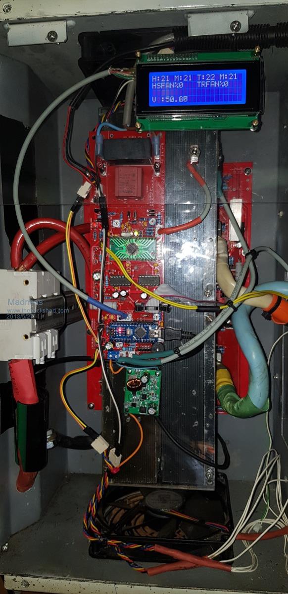
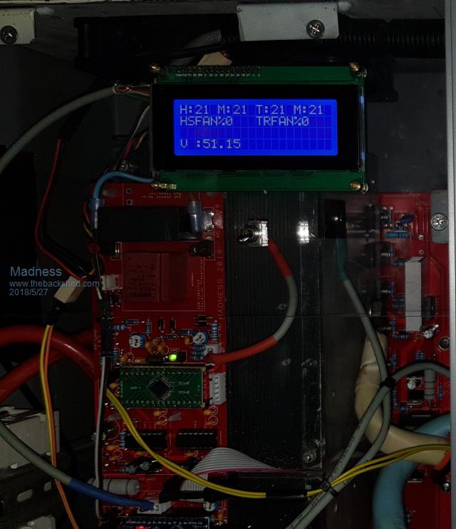
Today I fitted the new PCBs to my main 8KW Inverter that I had assembeled earlier. It is running perfectly with just the mods documented earlier for the control board and I have used shielded wire for the on/off switch. I also found a 9K1 resitor in place of the 7K5 just above the voltage adjustment trim pot gave me an output range of 200V to over 245V with a 230/12V transformer.   There are only 10 types of people in the world: those who understand binary, and those who don't. |
||||
| Tinker Guru Joined: 07/11/2007 Location: AustraliaPosts: 1904 |
Looking at your blue display, out of curiosity, what is the typical voltage range of your LA forklift battery bank? For comparison, my Lithium bank swings from 56V (absorbing) to 53V (50% discharged). I'm interested in this to find out what low voltage disconnect value you use. Klaus |
||||
Madness Guru Joined: 08/10/2011 Location: AustraliaPosts: 2498 |
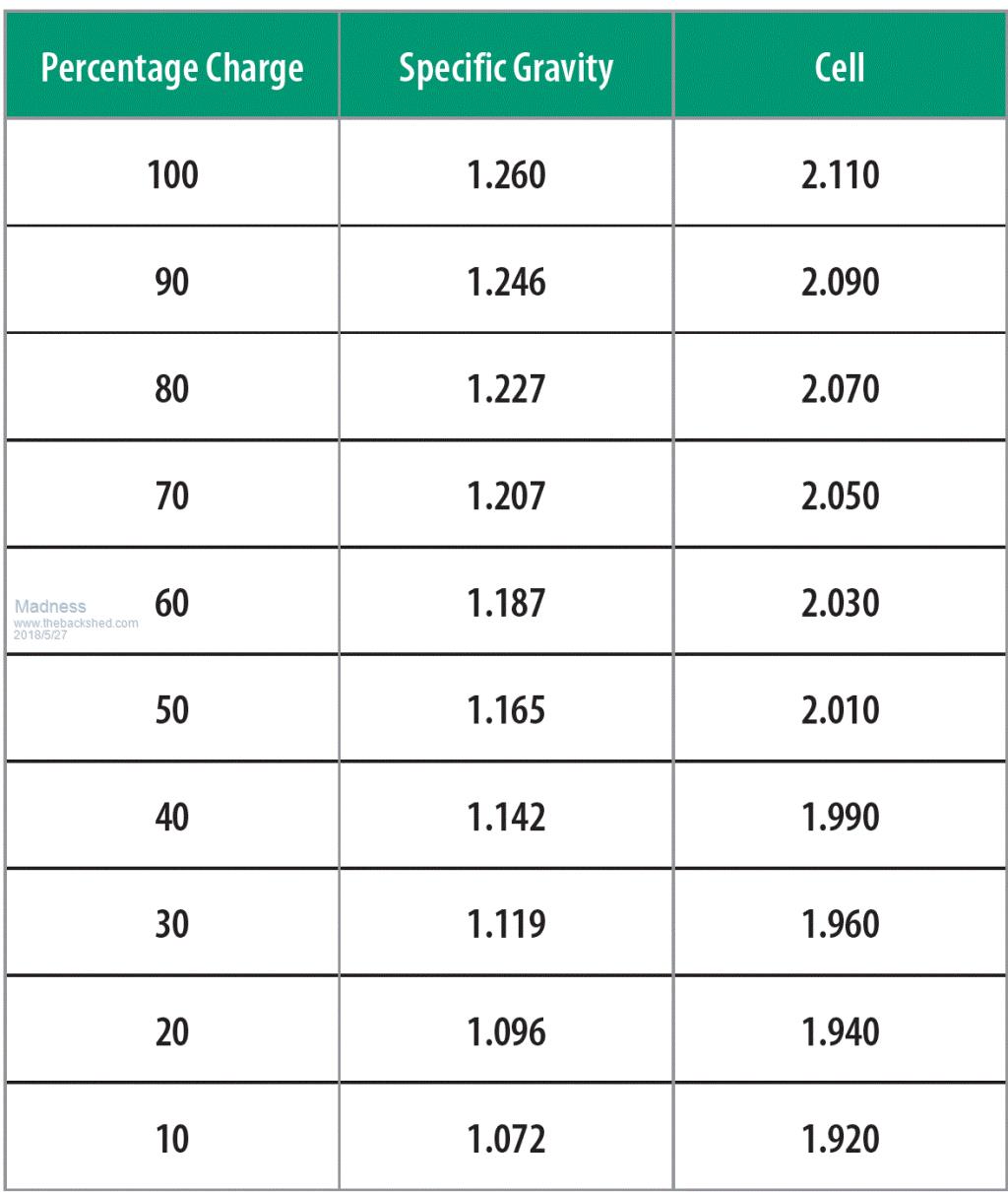
I work off this chart for state of charge 24 X the cell voltage.  30% is 47 volts which is absolutly as low as I would want to go where I have set the shutdown. In normal over night use it rarely gets below 50V, lowest I have gone to is 55% SOC. Normal Absorb voltage is 59.2 and 64V for Equalization (these are FLA). I am told in everyday use forklift batteries are expected to drawdown to 20% SOC and recharge over night, then do it all again the next day. The battery I have is guaranteed to do that for 5 years and still have 80% of it's original capacity. But none of those numbers mean anything for Lithium batteries. There are only 10 types of people in the world: those who understand binary, and those who don't. |
||||
| Tinker Guru Joined: 07/11/2007 Location: AustraliaPosts: 1904 |
" But none of those numbers mean anything for Lithium batteries." Quite correct, I was just curious at what percentage charge you set your low voltage shut down. I have been told my battery is flat at 48V so I set the LV trig point at 50.5V and hope it never gets that low. Your guarantee for second hand batteries is pretty good, I suppose its some sort of pro rata deal like one gets with new car batteries. Another question, on your big inverter, how stable is the mains voltage when you switch on a big load? On mine, set to 235VAC @ idle, it curiously increases a little with a big (~5KW) load. Klaus |
||||
Madness Guru Joined: 08/10/2011 Location: AustraliaPosts: 2498 |
I have never bothereed to look that closely at the output voltage, my experience has been it only changes by a point or 2 of one volt. There seems little reason to bother looking at further. The new version of my Charge Controller that I am working on will include monitoring the SOC. The Commercially made charge controller I use ATM counts Coulombs in less an efficiency factor and out of the battery. Everytime the battery enters float mode it resets to 100%. If the efficency factor is correct then the time the battery enters float mode will be very close to 100%. My charging goes to float when the current does not reduce while maintaining 59.2V. That current is 9.5A, I have not had reason to look at the charge requirments of Lithium to know if that would be any use with them. There are only 10 types of people in the world: those who understand binary, and those who don't. |
||||
| Tinker Guru Joined: 07/11/2007 Location: AustraliaPosts: 1904 |
Interesting, the output voltage here changes a lot more, like one or two volts. Might have to investigate why that is. For battery state of charge I use an independent coulometer, something like this:coulometer . Mine is an earlier version which had a 100Ah capacity limit. Since my bank is 200Ah I just used a bigger shunt (1/10th resistance of the original shunt) and mentally move the display decimal point so 20.0Ah on the display means 200Ah. This works quite accurate, only shows 100% when the charging current has backed right off to float. Klaus |
||||
| noneyabussiness Guru Joined: 31/07/2017 Location: AustraliaPosts: 513 |
battery monitor I use one of these... does everything and is even wireless I think it works !! |
||||