
|

|
Forum Index : Electronics : Various aspects of home brew inverters
| Author | Message | ||||
| poida Guru Joined: 02/02/2017 Location: AustraliaPosts: 1418 |
Not any time soon, Mark. wronger than a phone book full of wrong phone numbers |
||||
| wiseguy Guru Joined: 21/06/2018 Location: AustraliaPosts: 1156 |
Solar Mike, thanks for the suggested circuit - its essentially what I had in mind but without me having to design it. I have edited the next section extensively from what I first wrote to be hopefully easier to grasp. Poida, the scheme of modulation I suggested in the inverter failures post (pge 13) may solve the 50Hz timing issue, as separate 50 Hz timing is not required. The scheme requires a half sine wave PWM to toggle between the two output pins of the micro alternately each half cycle, the pin that is not outputting the PWM is simply held Low. ie there is only ever PWM signal from 1 of the 2 output pins at any given time. After each half cycle is finished and the PWM'd side returns to low again the PWM is transferred to the other pin for the next half cycle until it also returns to low again and the PWM is transferred back and forth like this continuously. The 50Hz component modulated within the HF PWM is all that is required to be accurate - I said in my previous post in inverter failures that there is no synchronous issues around zero as nothing is happening there any more. (except for swapping the 2 pin signals whilst they are both low - the FETs don't know it even happened - yet) If the micro is initialised with the 2 outputs idling at low - these outputs become the high side drives, their inverted/complement sense drives both lower FETs. One pin is sourcing the PWM to max and back to zero whilst the other pin does nothing (remains low) and then they swap over. In the absence of any output on the two micro output pins both lower FETs are held on and both upper FETs are held off If this is ambiguous or needs further explanation I can write it up better and email something to you - sometimes my technical explanations in posts have left a bit to be desired. I believe this would also be more efficient that PWM-ing both sides at the same time (bipolar), as for 50% of the time one side isn't switching so no switching losses. If you would be prepared to modify your code to a version 5, I would be most grateful to be able to try it - what would take you 15 minutes could take me a week or two - if I didnt break it further in the process :) Last thoughts, if the two consecutive half sines were identical (save the first half and re-feed it during the second half) it should guarantee the toroidal flux never walks. This is easy to write but might be difficult/impossible to actually code....... If at first you dont succeed, I suggest you avoid sky diving.... Cheers Mike |
||||
| gaspo Regular Member Joined: 25/06/2018 Location: AustraliaPosts: 65 |
Hi Poida, I wanted to see how well I can synchronize two timers on STM32F030. Timer TIM1 configured as master, 20kHz PWM 50% duty with complementary output. Timer TIM3 set as slave clocked from TIM1 at 20kHz, prescaled for 50Hz PWM with 50% duty. Timers were in sync down to 50ns. No inverter code just timers setup: 2018-11-12_004525_main.cpp.zip 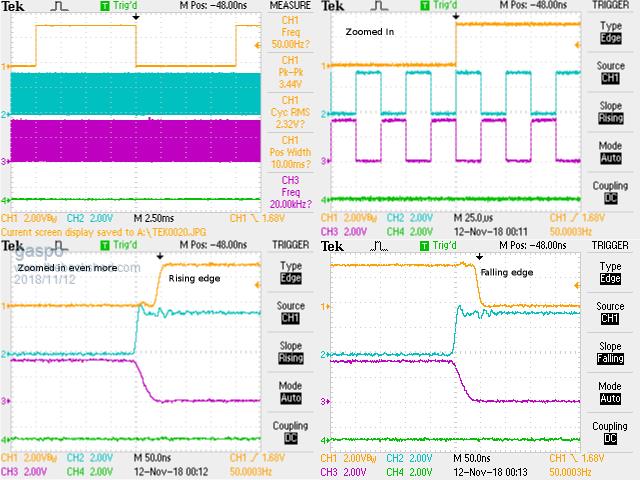 |
||||
| Tinker Guru Joined: 07/11/2007 Location: AustraliaPosts: 1904 |
Great work poida. I happen to have the same LCD board and adapter you show in your video. Now I'm wondering if this could be made to display the info in writing what that blinking status LED now does on the EG8010? Of course, you would need to do the programming  as I have zero chance there. as I have zero chance there.On another matter, Gaspo kindly programmed my Atmega nano 168P board to do the 2 sine wave inverter drive. This looks *very* promising indeed, nice clean wave forms and nice soft start/stop via push button. Now I'm experimenting with feeding these sine waves into two TLP350 opto isolators which in turn feeds the signals to IR2184 chips. If this works I'll get an inverter that runs from a nano which is electrically isolated from the power drive signals. To make this a fully operational inverter it would require over current and under voltage shut down facilities similar to the EG8010 and some kind of fan control via NTC sensor. Is this asking too much from the nano 328P I have on order? Klaus |
||||
| poida Guru Joined: 02/02/2017 Location: AustraliaPosts: 1418 |
Tinker, no, we have plenty of time to run code for over current and under voltage. Let's say you can deliver to an analog converter pin on the 328P a voltage that is scaled from the DC power board supply. You need to keep this between 0 and 5V. I would use a 10K multi turn trimpot, set it to give maybe 2.5V at low voltage cutoff. Place a 5V zener across it to clamp any voltages over 5V. Feed that into an ADC input. Maybe low pass filter it with an RC filter... The ADC conversion needs about 18us. Integer comparison with a low limit will take a few clock cycles, at 16MHz this is not a lot of time. Over current will require the provision of a 0 - 5V signal corresponding to current. DC input current? Probably. In the case of the Aliexpress inverter boards I use for my house inverter, there are 2 over current schemes. I disable both. I put a DC contact breaker on the supply and let the mighty HY4008s take care of business. But you want to have over current so which will it be.. The slow time constant filtered, average DC current limit is one way. You can also look for peak current, generated each 1/2 cycle of the 50Hz output. There is plenty of cpu cycles for you to do the peak current limit if needed. Just get a 0 - 5V signal of the DC current and don't filter it too much, feed it into the 5V zener protection diode then an ADC channel. Again, conversion takes 18us and less than one more usec for comparison with an upper limit. That would be the peak current limit. Maybe alternatively or as well as, take this signal, low pass filter it, again with an RC filter, time constant of a few seconds would be good, and feed it into an ADC channel. Once limits are exceeded, set a flag, soft stop the inverter and display info of limit excursion. wronger than a phone book full of wrong phone numbers |
||||
| poida Guru Joined: 02/02/2017 Location: AustraliaPosts: 1418 |
This looks very good. This would be an excellent basis for running inverter code. The 50ns overlap is insignificant since dead time circuitry will prevent such short pulses from getting the MOSFET gates. wronger than a phone book full of wrong phone numbers |
||||
| poida Guru Joined: 02/02/2017 Location: AustraliaPosts: 1418 |
To anybody who is playing with the 2x sin codes: I have discovered I overlooked some stuff. The 100Hz timer is not phase locked to the output AC waveform. My comments in the code are misleading. To make the 100Hz event remain locked to the AC output, I suggest you 1 - remove the TIMER2 code, and interrupt 2 - add a counter in TIMER1, counting up to 199 from 0. When at 199, set uf = 1, reset counter to 0. job done. And we don't need that other timer. The advantages are we get correct timing of when uf = 1, i.e. when we run the PID control which is zero crossing of AC output. And we get a much cleaner 20kHz PWM. It seems to maintain the output AC voltage a little better too. With the Arduino 328P, there is no interrupt priority. The first interrupt to fire will run it's code, then in the middle of that, another interrupt could fire, and then ITS code is run. I saw on the oscilloscope events when the 20KHz PWM code was delayed from completing (or delayed from starting!) due to TIMER2 firing it's code at the perfect time. 2018-11-12_185457_uno_inverter_2x_sinewave_pwm.ino.zip wronger than a phone book full of wrong phone numbers |
||||
| poida Guru Joined: 02/02/2017 Location: AustraliaPosts: 1418 |
Tinker, I'll sketch out a bit of code. I will implement over temp cut off, high temp fan output, under voltage cut off, (slow) over current. I will add AC output under voltage. Using the latest 2x sinewave code as a basis: We need a few globals, max current (16 bit int), min DC voltage (16 bit int), min AC voltage (16 bit int), fan ON limit (16 bit int), over temp limit (16 bit int) int fantemp, maxtemp, minvolts, max_current. float max_ac_error; All these variables need to initialised to required values, using the 0 - 1024 range of the analog to digital converter (ADC). We will keep then fixed in the program for now. You could alter trip points via external signal conditioning i.e opamp gain or resistor dividers etc. The 328P as found on the Arduino Uno has 6 analog inputs. AC output requires one and I assign it to ADC channel 2 AC output setpoint needs one, I assign it to channel 0 Max current will be channel 3 DC input voltage channel 4 Heat sink temp, via a NTC 10K resistor maybe?, channel 5 One ADC channel is unused. from within the block that executes when uf == 1, we can add if (ch2 < max_AC_error) { oen = 0; // maybe want or dont want to stop, dunno lcd.message("Output under voltage. Inverter stop"); } if (analogRead(3) > max_current) { oen = 0; // slow stop the program lcd.message("over current, inverter stop"); } if (analogRead(4) < minvolts) { oen = 0; lcd.message("DC LV cutoff. Inverter stop"); } if (analogRead(5) > fantemp) { //set pin3 HIGH, used to drive the fan supply, turning it on sbi(PORTD,2); } else { //set pin 3 low, turn off fan... cbi(PORTD,2); } if (analogRead(5) > maxtemp) { oen = 0; lcd.message("Over temp. Inverter stop."); } any time limits are exceeded, the inverter will need a restart. Adding these 4 ADC conversions and integer compares would add 80-90 us to the time needed to run the 100Hz PID update/soft start/soft stop code. It would not upset the PID functionality at all. We will likely need to add some timeout behavior to the low AC limit or else it will fire each time we switch a light on... You like this? wronger than a phone book full of wrong phone numbers |
||||
| poida Guru Joined: 02/02/2017 Location: AustraliaPosts: 1418 |
I must confess I had to read your post a few times to understand it. I think I get it. Let V1 and V2 be the primary winding node points. Looking at it at some random time we see: V1 = 0 volts and V2 doing a half sine, from 0 to DC supply and back to 0 then we see V2 = 0 volts and V1 doing the half sine, from 0 to DC supply and back to 0 rinse, repeat.. That is easy to code. Agreed it 1/2s the switching losses. And probably doubles the life of the MOSFETS too. I have not had much of a problem with DC in the primary winding (flux walking?) but maybe it's an issue that I'm overlooking and should worry. Time to get the 328P manual out again. Timer 1 is the only timer we can use that has the required clock speed and count range. Timer 1 outputs via pin 9 and 10. We need pin9 to hold low while 10 does SPWM, then pin 10 low while pin 9 does SPWM. I think we need to reconfigure the output compare on the fly, each 1/2 cycle. Lemme see. wronger than a phone book full of wrong phone numbers |
||||
| Tinker Guru Joined: 07/11/2007 Location: AustraliaPosts: 1904 |
I do  , looks good. , looks good.You are perhaps used to the idiosyncrasies of your made in China inverter but many here are used to the EG8010 chip's functions. These functions are basically all that's required, IMO, for a reliable inverter though the fan control could be to suit variable speed fans.. Over current, (the EG8010 has a 600ms delay before it trips to cater for switch on peaks) has worked for me so far. Of course, there are the DC & AC circuit breakers as backup but they might be slow at times. I do low battery voltage sensing by zener diodes turning on a transistor or not so all the nano requires is looking for a +5 or 0v input with 0V meaning battery is over 48V and its OK to soft start. So no proportional voltage divider sensing, just shutting the inverter down when 5V is at the sense input. AC voltage sensing is done already with the set output voltage feedback, one just needs to set upper and lower limits and shut down the inverter if the limits are exceeded for a predetermined time. Klaus |
||||
| poida Guru Joined: 02/02/2017 Location: AustraliaPosts: 1418 |
Wiseguy, well, that didn't take long.. Here is a DSO capture Yellow is V1 , Arduino Pin 9, (to a half bridge, so the IR2184 produces low and high side drives) Light Blue is V2 (Arduino pin 10) Dark Blue is AC output. When V1 is pulled low, V2 gets a half wave, then V2 is pulled low and V1 gets a 1/2 wave. 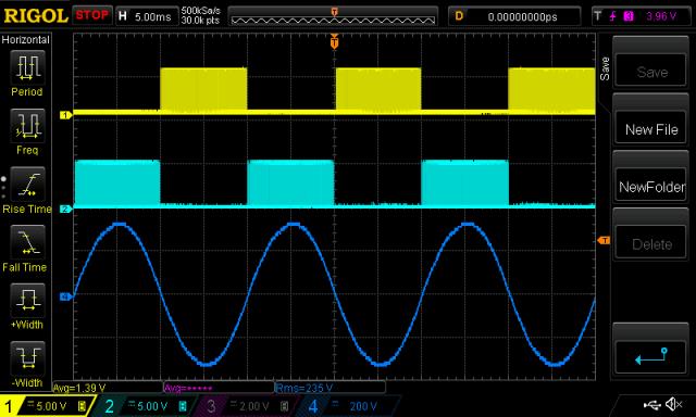 Using my crappy UNI-T DC clamp meter, I see very low DC current in the primary. Maybe 0.2 A. This is on top of 6 Amp AC. Code is 2018-11-12_211512_uno_inverter_2x_sine_wiseguy.ino.zip The IR2184 input is reflected on the low and high outputs as follows: input low = lowside HIGH, highside LOW input high = lowside LOW, highside HIGH The highside drives get their DC supply from a charge pump, and so it wont work on DC. But it works! What now... (did I pass the test and I can work for you?) Idle current for this code is 0.40A, compared with the 2x sine code which is 0.48A Both tested at 27.4V supply, 235V AC output. I noticed the 1500VA toroid ran quieter when running your suggested code. Here is the FFT from the output when under 150W test load. 10db/div. The THD must be tiny! 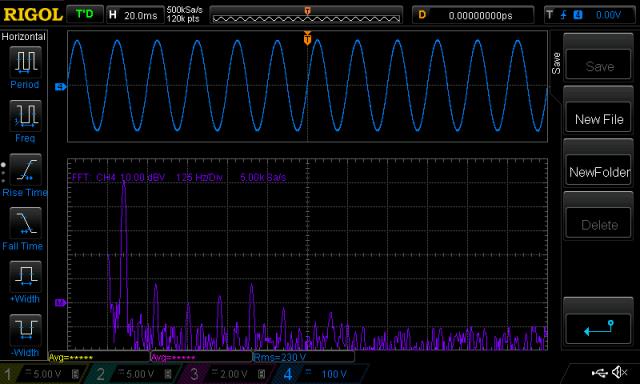 F3 -42db F5 -50db F7 -47db F9 -42db wronger than a phone book full of wrong phone numbers |
||||
| wiseguy Guru Joined: 21/06/2018 Location: AustraliaPosts: 1156 |
Poida, You described it reworded perfectly ! Looking at all the activity here you're gonna need a shorthand secretary soon or you wont get any coding done. Would you prefer to leave my request for a bit whilst you finish the other bits and add ons you are doing - I guess an upside is that the code I am after to play with can have them too ? Tinker - you mentioned trying my alternate output drive - are you talking about Gaspos board with 4 cross conduction transistors or the symmetrical drive Poida described quite well above ? If at first you dont succeed, I suggest you avoid sky diving.... Cheers Mike |
||||
| wiseguy Guru Joined: 21/06/2018 Location: AustraliaPosts: 1156 |
Poida what took you so long :) I am in awe of your coding abilities - would be happy to work with you anytime - you got the job!! In return next time you have something that needs a PCB Ill find Gaspos address - just kidding - I would be happy to do it for you. If at first you dont succeed, I suggest you avoid sky diving.... Cheers Mike |
||||
| wiseguy Guru Joined: 21/06/2018 Location: AustraliaPosts: 1156 |
During lowside high (highside low), the upper Fet bootstrap capacitor is charging/charged. When its time for it to pwm, the charge pump stays charged continually on each lowside high. It should work with bootstraps - although personally I am not a big fan and would never use them for a high powered application. If at first you dont succeed, I suggest you avoid sky diving.... Cheers Mike |
||||
| Tinker Guru Joined: 07/11/2007 Location: AustraliaPosts: 1904 |
The one that gaspo showed a pic of in his last post. I have gaspo's board with just the 4 anti cross conduction transistors as well but its output is identical to an unmodified EG8010 board. Klaus |
||||
| wiseguy Guru Joined: 21/06/2018 Location: AustraliaPosts: 1156 |
This post will also be copied to the random failures heading where it really belongs as a respone to Tinkers post. I just found the post of Gaspos you referred to - somehow I missed it. I was unaware of the boards existence, so it appears Gaspo was playing with a hardware version whilst Poida was coding the alternate symmetrical drive. I really cannot fathom why the EG8010 guys did not elect to use this scheme as standard for their unipolar drive - it is uncomplicated elegant efficient quiet and least likely to have any bad behaviour issues. I had stalled on my controller board as I was totally unimpressed with the general behaviour of the EG8010 with or without cross conduction transistors. I was adding so many bandaids & gating around it that I started (begrudgingly) looking for a micro-controller solution. At about this point Poida & Gaspo were perfecting a great Arduino solution that would easily adapt the alternate scheme. Poida can you please confirm that the, USB Nano V3.0 ATmega328 16M 5V Micro-controller CH340G board For Arduino Module will work with your code? If at first you dont succeed, I suggest you avoid sky diving.... Cheers Mike |
||||
| poida Guru Joined: 02/02/2017 Location: AustraliaPosts: 1418 |
My theory is someone saw the EG8010's drive scheme implemented in some Very Expensive Foreign Gear and thought, "we can copy this, put it in a chip costing $2 and no problems". When copying it, they might have not seen why this awkward scheme was employed, but shrugged shoulders and just cloned it. This all occurred in China. All Arduino Nanos use the ATmega 328 (it's required by the standard design of the Nano), and so no problem. The Nano board leads out enough ADC channels, digital pins 2 - 10. I guess you have your eye on a few of these? The image of the board clearly shows ATmega328P uC. 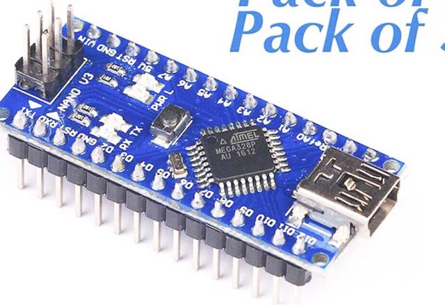 I can get a much better low pass filter on the DSO inputs with the oscilloscope here at work. This shows the LP filtered drives of pins 10 and 9, and the purple trace is one subtracted from the other. 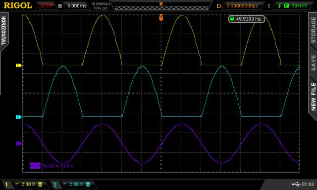 I probably will use this code as the basis for further work. I like the lower DC current in the primary winding compared with anything else I have tested. I like the toroid's silent running. It's eerie running an inverter and hearing no hum at all at idle. The LC primary filter is doing it's job to a high level of suppression of harmonics too (45uH, 10uF cap) So I suppose I better start coding some creature comforts (the boring bits in my view) eg low voltage cut off, over current trip, LCD support I think it possible to include 50/60Hz support too. The code is smaller and less time is spent in the TIMER1 interrupt block, which frees some cycles for the creature comforts. wronger than a phone book full of wrong phone numbers |
||||
| tinyt Guru Joined: 12/11/2017 Location: United StatesPosts: 438 |
Hi poida, when you have the time, will appreciate if you can post changes for 60Hz. Thanks |
||||
| wiseguy Guru Joined: 21/06/2018 Location: AustraliaPosts: 1156 |
Poida, I probably should have consulted you first - my Nano was much more expensive (by 81c) but its got more "stuff" on it - not sure if that is an asset or not.... 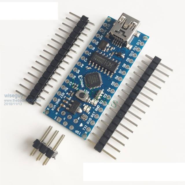 Their Descriptions: CH340G Replace FT232RL Operating Voltage(logic level):5V 8 analog inputs ports:A0 ~ A7 14 Digital input / output ports:TX,RX,D2 ~ D13 6 PWM ports:D3, D5, D6, D9, D10, D11 1 pairs of TTL level serial transceiver ports RX / TX Using Atmel Atmega328P-AU MCU There is bootloader installed in it Support USB download and Power Support for external 5V ~ 12V DC power supply Support power supply by 9V battery Should I turf it and use exactly what you are using to avoid issues or give it a go? It currently looks as sad as the picture..... I just saw the rest of the pictures - yours has lots of stuff too under the pcb..... If at first you dont succeed, I suggest you avoid sky diving.... Cheers Mike |
||||
| gaspo Regular Member Joined: 25/06/2018 Location: AustraliaPosts: 65 |
Wiseguy, your Nano will work fine. It has the same amount of analog and digital pins as Uno - just smaller form factor. |
||||